EP0111087A1 - Appareil aspirateur de drainage médical - Google Patents
Appareil aspirateur de drainage médical Download PDFInfo
- Publication number
- EP0111087A1 EP0111087A1 EP83109990A EP83109990A EP0111087A1 EP 0111087 A1 EP0111087 A1 EP 0111087A1 EP 83109990 A EP83109990 A EP 83109990A EP 83109990 A EP83109990 A EP 83109990A EP 0111087 A1 EP0111087 A1 EP 0111087A1
- Authority
- EP
- European Patent Office
- Prior art keywords
- control chamber
- suction control
- suction
- pressure
- disposed
- Prior art date
- Legal status (The legal status is an assumption and is not a legal conclusion. Google has not performed a legal analysis and makes no representation as to the accuracy of the status listed.)
- Granted
Links
Images

Classifications
-
- A—HUMAN NECESSITIES
- A61—MEDICAL OR VETERINARY SCIENCE; HYGIENE
- A61M—DEVICES FOR INTRODUCING MEDIA INTO, OR ONTO, THE BODY; DEVICES FOR TRANSDUCING BODY MEDIA OR FOR TAKING MEDIA FROM THE BODY; DEVICES FOR PRODUCING OR ENDING SLEEP OR STUPOR
- A61M1/00—Suction or pumping devices for medical purposes; Devices for carrying-off, for treatment of, or for carrying-over, body-liquids; Drainage systems
- A61M1/60—Containers for suction drainage, adapted to be used with an external suction source
- A61M1/61—Two- or three-bottle systems for underwater drainage, e.g. for chest cavity drainage
-
- A—HUMAN NECESSITIES
- A61—MEDICAL OR VETERINARY SCIENCE; HYGIENE
- A61M—DEVICES FOR INTRODUCING MEDIA INTO, OR ONTO, THE BODY; DEVICES FOR TRANSDUCING BODY MEDIA OR FOR TAKING MEDIA FROM THE BODY; DEVICES FOR PRODUCING OR ENDING SLEEP OR STUPOR
- A61M1/00—Suction or pumping devices for medical purposes; Devices for carrying-off, for treatment of, or for carrying-over, body-liquids; Drainage systems
- A61M1/71—Suction drainage systems
- A61M1/73—Suction drainage systems comprising sensors or indicators for physical values
- A61M1/732—Visual indicating means for vacuum pressure
-
- A—HUMAN NECESSITIES
- A61—MEDICAL OR VETERINARY SCIENCE; HYGIENE
- A61M—DEVICES FOR INTRODUCING MEDIA INTO, OR ONTO, THE BODY; DEVICES FOR TRANSDUCING BODY MEDIA OR FOR TAKING MEDIA FROM THE BODY; DEVICES FOR PRODUCING OR ENDING SLEEP OR STUPOR
- A61M1/00—Suction or pumping devices for medical purposes; Devices for carrying-off, for treatment of, or for carrying-over, body-liquids; Drainage systems
- A61M1/71—Suction drainage systems
- A61M1/74—Suction control
- A61M1/742—Suction control by changing the size of a vent
Definitions
- the present invention relates to drainage of fluids from body cavities and, more particularly, to an apparatus for use in draining fluids from the chest cavity.
- the thoracic or chest cavity is a closed structure essentially formed by the thoracic skeleton and muscles.
- the interior of the thoracic cavity is partitioned by the mediastinum, which consists of connective tissue which surrounds and holds together the esophagus, trachea, heart, aorta and other major vessels.
- the mediastinum divides the interior of the thoracic cavity into lung chambers (called pleural cavities), each of which contains one of the lungs.
- the lungs are composed of elastic fibers which expand and contract during the normal breathing process. Expansion of the lung occurs during inhalation. When a person inhales, the diaphragm, which is mostly muscle, contracts and pulls downward. At the same time the chest muscles pull the chest wall up and out, with the result that the two chambers inside the thoracic cavity are expanded. The expansion of the two chambers in the thoracic cavity creates a negative pressure which exerts a pull on the lungs causing the lungs to expand and thereby allowing air to be drawn into the lungs. Similarly, during exhalation the rib cage and diaphragm contract, reducing the negative pressure in the two chambers which reduces the force on the lungs allowing them to contract so that sir is exhaled.
- the air and other fluids which have entered the pleural cavity must be removed from around the lung. This is typically accomplished by inserting one or more chest catheters into the pleural cavity and then connecting the catheters to a drainage system which is used to collect the fluids drained from the pleural. cavity.
- one type of system utilizes gravity to effect drainage of: the fluids from the pleural cavity.
- a bottle is placed below the level of the patient's chest.
- the bottle is closed at its top by a rubber stopper through which a drainage tube is inserted.
- the drainage tube is attached at one end to the catheter inserted into the patient's chest.
- the other end of the drainage tube extends through the stopper to a point near the bottom of the bottle.
- a sterile liquid such as saline solution is used to fill the bottle to a point which covers the end of the drainage tube.
- the sterile liquid is intended to act as a seal or one-way check valve which prevents air from moving back up through the drainage tube to the patient's chest.
- the bottle is also vented to atmosphere through the rubber stopper so that.when the bottle is placed below the level of the patient's chest, gravity will effect drainage of fluid from the pleural cavity into the drainage bottle.
- Suction drainage systems typically include a water manometer which is connected to a source of suction and which controls the level of suction applied to the pleural cavity of the patient, since an uncontrolled level of suction may damage the surrounding tissue.
- the manometer bottle is in turn connected to a bottle which contains a water seal similar to the type of water seal used in a grayity drainage system.
- the bottle containing the water seal may then be also connected to a third bottle which is used as the drainage bottle for collecting the fluids that are drained from the patient's chest cavity.
- One important object of the present invention is to provide an apparatus for draining fluids from the body cavity of a patient which includes structure for effectively sealing the drainage system to prevent backflow of drained fluids but which seal is accomplished without the use of an underwater seal.
- Another important object of the present invention is to provide an apparatus for draining fluids from a body cavity which is simple in its construction, compact, easy to handle and which can be economically disposed of after each use.
- Yet another important object of the present invention is to provide an apparatus which combines in a simple and effective way the structure for accomplishing pressure regulation and sealing of a suction drainage system.
- a small, disposable suction control chamber contains a novel check valve and structure for regulating the amount of suction applied to the catheter and drainage tube inserted into the pleural cavity of a patient.
- the disposable suction control chamber may be removably mounted on a standard suction collection apparatus which is used for receiving the fluids drained from the pleural cavity.
- the check valve effectively prevents backflow of the drained fluids without the use of an underwater seal as in the prior art type suction drainage systems.
- the pressure regulating structure of the suction control chamber also eliminates the need for a water manometer and thus permits the suction collection chamber to be constructed in a very compact size so that it can be economically disposed of after each use.
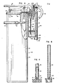
- a patient 10 is schematically illustrated with two drainage tubes 12, 14 connected in flow communication with his thoracic cavity.
- the number of tubes so used depends upon the nature of the procedure and is not a limiting feature of the present invention.
- the drainage tubes 12, 14 are connected to respective legs of a Y-connector 16 so as to feed a common flow tube 18 connected to the stem of the connector 16.
- Flow tube 18 is connected to a fitting 20 (see FIGURE 2) which projects upwardly from the cover 24 of a suction collection container generally designated at 22, to form a first flow path 23.
- a second fitting 26 projects through cover 24 to which a further flow tube 28 has one of its ends 28a connected.
- tube 28 is connected to an inlet fitting 32 projecting upwardly from the top wall or cover 34 of a suction control chamber designated at 30.
- An outlet fitting 36 also projects upwardly from cover 34 and is connected to an adjustable control valve 38.
- Inlet fitting 32 and outlet fitting 36 are connected in series to form part of a second flow path 37 through which negative or suction pressure is adjustably applied to the interior of suction control chamber 30 by means of valve 38, which is connected by tubes 40 and 41 to a negative pressure or vacuum source (not shown).
- the relatively small suction control chamber 30 can be mounted on the larger suction collection container 22 by means of the cover 34.
- the cover 34 (see FIGURE 2) includes a horizontal projection 42 which engages fitting 20 through aperture 43.
- suction applied to chamber 30 is transmitted to container 22 via tube 28. From container 22 the suction is applied to the chest cavity of patient 10 via tubes 18, 12 and 14. Liquid drawn through tubes 12, 14 and 18 is thus suctioned into and collected in container 22 while drained gases pass above the collected liquid, through tube 28 to chamber 30 where they are exhausted through tubes 40 and 41 by the vacuum source.
- the suction collection container 22 may be any suitable type of suction collection apparatus for effecting thoracic drainage, such as for example the apparatus illustrated and described in U.S. Patent No. 3,719,197 which is incorporated herein by reference.
- the suction collection container 22 includes a rigid outer canister 43 that is cylindrical in shape, although the shape is not critical.
- the rigid outer canister 43 is enclosed at its top by a cover 24 which has a depending flange 45 for air-tight engagement over the upper open end of the canister 43.
- a plastic receiver or canister liner 44 depends from the cover 24 and is fused or otherwise secured to the underside of the cover 24 entirely around the upper periphery of the liner 44 as indicated at 47 (see Figure 3).
- the cover 24 is preferably of a relatively rigid plastic material, while the liner or receiver 44 which depends from the cover 24 is preferably a flexible thermoplastic material.
- the securement of the upper end portion of the liner 44 to the cover 24 is completely air-tight and positive.
- the liner receiver 44 is therefore completely sealed except for fittings 20 and 26, which may conveniently be molded as part of the cover 24 and which project from the cover 24 into the interior of the liner receiver 44.
- the outer canister 43 has a T fitting 49 (See also figure 2a) secured to nipple 51 in the wall of the canister 43.
- T fitting 49 See also figure 2a
- one arm of the T fitting 49 is connected by tube 40 to the outlet fitting 36 of the control valve 38 on the suction control chamber 30.
- the other arm of the T fitting 49 is connected to the tubing 41 connected to the source of suction (not shown) used to effect drainage of the patient's chest cavity.
- a resilient, one-way flutter valve 53 is attached at the nipple 51 and is enclosed by the collar portion 70 of T fitting 49. If suction through tube 41 is terminated, a positive pressure is established across valve 53 from its outlet and 53a to its inlet end 53b, which serves to help seal valve 53. Valve 53 thus prevents the loss of vacuum from the inside of canister 43 and subsequent collapse of the liner 44 if the source of vacuum is disconnected for any reason.
- the vacuum or negative pressure applied through tube 41 is communicated through the collar portion 70 of T fitting 49 and through valve 53 to the interior of the ,rigid canister 43.
- negative pressure or vacuum created inside the interior of the receiver or liner 44 is countervailed by the vacuum that is established inside of the canister 43 but outside the liner 44, thus preventing collapsing of the liner receiver .44 during the time that the vacuum is applied.
- the liner receiver 44 is heat sealed or otherwise secured to the cover 24 once the liner has been completely filled with the fluids drained from the patient's chest cavity, the cover 24 and liner receiver 44 may simply be removed and disposed of intact. This eliminates the need for having to wash and resterilize the suction collection container 22 and also eliminates additional risk of contamination to nurses and other hospital staff.
- Inlet fitting 32 extends through the cover 34 of chamber 30 and has its interior end engaged within one end of an elastomeric duck-bill member generally designated at 46.
- Duck-bill member 46 is a radially flattened, elongated elastomeric tube which, in its unflexed state, prevents axial flow therethrough because its opposed flattened surfaces 55, 57 abut one another.
- the ingress end 46a of member 46 is stretched over the interior end 32a of fitting 32 and may be annularly clamped thereto by a clamping ring 48, or bonded directly to fitting 32.
- the inlet opening 32b of fitting 32 thus communicates with the interior of the resiliently expanded portion 50 of the member 46.
- Member 46 can be made of any elastomeric material and, in the preferred embodiment, is made of natural rubber.
- Clamping ring 48 is made of latex or other similar material suitable for clamping the ingress end 46a of member 46 about fitting 32.
- Outlet fitting 36 is secured to the external side of cover 34 to valve 38 by means of a friction fit or the- like.
- Valve 38 may be any suitable metering valve and, in the preferred embodiment, includes a threaded interior bore 52.
- a screw 54 threadingly engages bore 52.
- An outlet fitting 56 is.adapted to be connected to tube 40 and has a throughbore 61 that communicates with the interior bore 52. By adjusting the depth of screw 54 in bore 52, the flow restriction between fittings 56 and 36 can be varied so as to adjust the suction or negative pressure applied to the interior of suction control chamber 30.
- valve 38 may be replaced by a flow restrictor 60 which is adapted to engage fitting 36 in a friction fit, or which may be bonded thereto.
- Flow restrictor 60 has a flow path which includes a narrowed portion 62 which restricts gaseous flow and thereby limits the suction pressure applied to chamber 30.
- the size of the restriction provided by bore 62 (see Figure 4) or screw 54 (see Figure 3) should be designed so that gaseous flow through the restriction will be maintained at sonic velocity over a range of absolute line pressures in tube 40 from approximately zero to one-half an atmosphere.
- the restrictor 62 is sized at .0465 in., which causes a constant flow rate which in combination with aperture 66 results in an essentially constant negative pressure of about 20 cm of water using typical hospital vacuum wall outlets or portable vacuum pumps. This level of suction can be safely applied to the pleural cavity without damaging surrounding tissue.
- the pressure within suction control chamber 30 is monitored by means of a pressure monitoring tube 64.
- Tube 64 preferably has gradations (not shown) spaced longitudinally along its exterior and calibrated in units of pressure.
- the tube 64 is oriented vertically within suction control chamber 30 and has its lower end communicating with the ambient pressure outside of chamber 30 by means of a small aperture 66 located in the bottom wall of the chamber 30.
- Aperture 66 its sized so that it is slightly larger than the flow restriction provided by screw 54 or restrictor tube 60.. Using the example noted above wherein restrictor 62 is: .0465 in., a suitable size for aperture 66 would be .078 in.
- the tube 64 is molded integrally with the bottom wall of chamber 30, with the lower end of the tube disposed concentrically about aperture 66.
- a round projection 67 having one or more slots 69 is formed on the bottom of chamber 30 and surrounds the aperture 66. The projection 67 prevents occlusion of the aperture 66 by a finger or by other objects.
- a ball 68 or other relatively light-weight pressure responsive indicator is disposed within tube 64, which has its upper end open to the interior of chamber 30.
- Ball 68 is typically made of polypropylene or similar material.
- the level attained by the ball corresponds to the magnitude of the pressure differential across tube 64 and hence, reflects the pressure level within chamber 30.
- the calibrated gradations (not shovm) on tube 64 provide a reading of that pressure as a function of the height attained by the ball within tapered tube 64.
- chamber 30 is a transparent plastic cylinder having an inside diameter of 1.690 inches, an outside diameter of 1.750 inches, and an axial length of 4.425 inches.
- the base of the chamber is preferably formed integrally with the cylinder and has an axial depth of 0.150 inches.
- Pressure monitoring tube 64 is preferably formed integrally with the chamber base and has an axial length of 4.000 inches.
- the outer diameter of tube 64 is 0.410 inch and the inner diameter tapers from 0.250 inch at its lower end to 0.350 inch at its upper end.
- Duck bill member 46 is 4.000 inches long, 0.800 inch wide and 0.062 inch thick.
- a typical range of pressure calibration of tube 64 is between zero to twenty centimeters of water.
Landscapes
- Health & Medical Sciences (AREA)
- Heart & Thoracic Surgery (AREA)
- General Health & Medical Sciences (AREA)
- Vascular Medicine (AREA)
- Engineering & Computer Science (AREA)
- Anesthesiology (AREA)
- Biomedical Technology (AREA)
- Hematology (AREA)
- Life Sciences & Earth Sciences (AREA)
- Animal Behavior & Ethology (AREA)
- Public Health (AREA)
- Veterinary Medicine (AREA)
- Pulmonology (AREA)
- External Artificial Organs (AREA)
- Medicines Containing Material From Animals Or Micro-Organisms (AREA)
- Acyclic And Carbocyclic Compounds In Medicinal Compositions (AREA)
- Sink And Installation For Waste Water (AREA)
- Electrical Discharge Machining, Electrochemical Machining, And Combined Machining (AREA)
- Water Treatment By Sorption (AREA)
- Separation Of Particles Using Liquids (AREA)
- Pipeline Systems (AREA)
- Drying Of Gases (AREA)
- Media Introduction/Drainage Providing Device (AREA)
Priority Applications (1)
| Application Number | Priority Date | Filing Date | Title |
|---|---|---|---|
| AT83109990T ATE27774T1 (de) | 1982-10-15 | 1983-10-06 | Absaugdraenagegeraet fuer medizinische zwecke. |
Applications Claiming Priority (2)
| Application Number | Priority Date | Filing Date | Title |
|---|---|---|---|
| US43468182A | 1982-10-15 | 1982-10-15 | |
| US434681 | 1982-10-15 |
Publications (2)
| Publication Number | Publication Date |
|---|---|
| EP0111087A1 true EP0111087A1 (fr) | 1984-06-20 |
| EP0111087B1 EP0111087B1 (fr) | 1987-06-16 |
Family
ID=23725229
Family Applications (1)
| Application Number | Title | Priority Date | Filing Date |
|---|---|---|---|
| EP83109990A Expired EP0111087B1 (fr) | 1982-10-15 | 1983-10-06 | Appareil aspirateur de drainage médical |
Country Status (9)
| Country | Link |
|---|---|
| EP (1) | EP0111087B1 (fr) |
| JP (1) | JPS5991963A (fr) |
| AT (1) | ATE27774T1 (fr) |
| AU (1) | AU563105B2 (fr) |
| CA (1) | CA1216208A (fr) |
| DE (1) | DE3372071D1 (fr) |
| DK (1) | DK165623C (fr) |
| ES (1) | ES8501236A1 (fr) |
| IE (1) | IE56123B1 (fr) |
Cited By (9)
| Publication number | Priority date | Publication date | Assignee | Title |
|---|---|---|---|---|
| US4650476A (en) * | 1985-10-18 | 1987-03-17 | Becton, Dickinson And Company | Chest drainage apparatus with adjustable suction control |
| US4664660A (en) * | 1985-04-01 | 1987-05-12 | Becton, Dickinson And Company | Chest drainage apparatus with ambient air sealing |
| DE3640124A1 (de) * | 1985-11-27 | 1987-06-04 | Medi Medical Instr I Aaryd Ab | Pumpenvorrichtung und ueberwachungseinrichtung zur verwendung bei plauradrainagen |
| DE3724483A1 (de) * | 1987-01-20 | 1988-07-28 | Medinorm Ag | Saugflasche zum absaugen von wundfluessigkeiten |
| US6537495B1 (en) | 1997-09-26 | 2003-03-25 | Edwards Lifesciences Llc | Vacuum-assisted venous drainage system with rigid housing and flexible reservoir |
| EP1314441A1 (fr) * | 2001-11-27 | 2003-05-28 | Datex-Ohmeda, Inc. | Siphon jetable avec régulation du vide pour un systeme de drainage thoracique |
| GB2560365A (en) * | 2017-03-09 | 2018-09-12 | Brightwake Ltd | Improvements relating to apparatus negative pressure wound therapy |
| CN113082319A (zh) * | 2021-04-13 | 2021-07-09 | 黄尚校 | 一种肿瘤科用积液抽取设备 |
| CN113842510A (zh) * | 2021-09-06 | 2021-12-28 | 苏州双福智能科技有限公司 | 一种大健康智能医疗集液系统及控制方法 |
Families Citing this family (5)
| Publication number | Priority date | Publication date | Assignee | Title |
|---|---|---|---|---|
| US4605400A (en) * | 1984-05-04 | 1986-08-12 | Bioresearch Inc. | Surgical drainage apparatus |
| DE3776990D1 (de) * | 1986-07-02 | 1992-04-09 | Sherwood Medical Co | Medizinische sauganordnung. |
| US4784642A (en) * | 1986-10-07 | 1988-11-15 | Pfizer Hospital Products Group, Inc. | Meterless drainage device with suction control |
| AU571134B1 (en) * | 1987-01-05 | 1988-03-31 | Lolatgis, A. | Pneumothorax valve |
| DE69529165T2 (de) * | 1994-10-11 | 2003-10-02 | Res Medical Pty Ltd | Verbesserte Vorrichtung zur Wunddrainage |
Citations (6)
| Publication number | Priority date | Publication date | Assignee | Title |
|---|---|---|---|---|
| US3363627A (en) | 1966-10-20 | 1968-01-16 | Deknatel Inc | Underwater drainage apparatus |
| US3363626A (en) | 1966-03-17 | 1968-01-16 | J A Deknatel Inc | Underwater drainage apparatus |
| US3719197A (en) | 1971-03-04 | 1973-03-06 | Voys Inc Le | Aseptic suction drainage system and valve therefor |
| US3750692A (en) * | 1972-01-11 | 1973-08-07 | E Tibbs | Chest drainage system |
| US4112948A (en) * | 1976-05-07 | 1978-09-12 | Deknatel, Inc. | Surgical drainage system with pressure indicator and enclosed source of liquid |
| US4195633A (en) * | 1977-11-07 | 1980-04-01 | International Paper Company | Chest drainage system with visual float means |
Family Cites Families (4)
| Publication number | Priority date | Publication date | Assignee | Title |
|---|---|---|---|---|
| US4018224A (en) * | 1976-04-07 | 1977-04-19 | Deknatel, Inc. | Underwater drainage device with dual collection chambers |
| CA1178866A (fr) * | 1980-06-06 | 1984-12-04 | Donald P. Elliott | Appareil de drainage thoracique |
| US4372336A (en) * | 1980-06-17 | 1983-02-08 | Sherwood Medical Industries, Inc. | Chest drainage unit |
| US4544370A (en) * | 1982-05-24 | 1985-10-01 | C. R. Bard, Inc. | Air leak detection system for chest fluid collection bottles and blow-out prevention baffle |
-
1983
- 1983-09-28 AU AU19675/83A patent/AU563105B2/en not_active Ceased
- 1983-10-06 EP EP83109990A patent/EP0111087B1/fr not_active Expired
- 1983-10-06 AT AT83109990T patent/ATE27774T1/de not_active IP Right Cessation
- 1983-10-06 DE DE8383109990T patent/DE3372071D1/de not_active Expired
- 1983-10-12 CA CA000438868A patent/CA1216208A/fr not_active Expired
- 1983-10-14 ES ES526478A patent/ES8501236A1/es not_active Expired
- 1983-10-14 IE IE2430/83A patent/IE56123B1/en not_active IP Right Cessation
- 1983-10-14 JP JP58191046A patent/JPS5991963A/ja active Granted
- 1983-10-14 DK DK475883A patent/DK165623C/da not_active IP Right Cessation
Patent Citations (6)
| Publication number | Priority date | Publication date | Assignee | Title |
|---|---|---|---|---|
| US3363626A (en) | 1966-03-17 | 1968-01-16 | J A Deknatel Inc | Underwater drainage apparatus |
| US3363627A (en) | 1966-10-20 | 1968-01-16 | Deknatel Inc | Underwater drainage apparatus |
| US3719197A (en) | 1971-03-04 | 1973-03-06 | Voys Inc Le | Aseptic suction drainage system and valve therefor |
| US3750692A (en) * | 1972-01-11 | 1973-08-07 | E Tibbs | Chest drainage system |
| US4112948A (en) * | 1976-05-07 | 1978-09-12 | Deknatel, Inc. | Surgical drainage system with pressure indicator and enclosed source of liquid |
| US4195633A (en) * | 1977-11-07 | 1980-04-01 | International Paper Company | Chest drainage system with visual float means |
Cited By (13)
| Publication number | Priority date | Publication date | Assignee | Title |
|---|---|---|---|---|
| US4664660A (en) * | 1985-04-01 | 1987-05-12 | Becton, Dickinson And Company | Chest drainage apparatus with ambient air sealing |
| US4650476A (en) * | 1985-10-18 | 1987-03-17 | Becton, Dickinson And Company | Chest drainage apparatus with adjustable suction control |
| DE3640124A1 (de) * | 1985-11-27 | 1987-06-04 | Medi Medical Instr I Aaryd Ab | Pumpenvorrichtung und ueberwachungseinrichtung zur verwendung bei plauradrainagen |
| DE3724483A1 (de) * | 1987-01-20 | 1988-07-28 | Medinorm Ag | Saugflasche zum absaugen von wundfluessigkeiten |
| US6537495B1 (en) | 1997-09-26 | 2003-03-25 | Edwards Lifesciences Llc | Vacuum-assisted venous drainage system with rigid housing and flexible reservoir |
| US6712799B2 (en) | 2001-11-27 | 2004-03-30 | Datex-Ohmada, Inc. | Disposable water seal for thoracic regulators |
| EP1314441A1 (fr) * | 2001-11-27 | 2003-05-28 | Datex-Ohmeda, Inc. | Siphon jetable avec régulation du vide pour un systeme de drainage thoracique |
| GB2560365A (en) * | 2017-03-09 | 2018-09-12 | Brightwake Ltd | Improvements relating to apparatus negative pressure wound therapy |
| GB2560365B (en) * | 2017-03-09 | 2021-10-20 | Brightwake Ltd | Improvements relating to apparatus negative pressure wound therapy |
| US11878108B2 (en) | 2017-03-09 | 2024-01-23 | Brightwake Limited | Apparatus negative pressure wound therapy |
| CN113082319A (zh) * | 2021-04-13 | 2021-07-09 | 黄尚校 | 一种肿瘤科用积液抽取设备 |
| CN113842510A (zh) * | 2021-09-06 | 2021-12-28 | 苏州双福智能科技有限公司 | 一种大健康智能医疗集液系统及控制方法 |
| CN113842510B (zh) * | 2021-09-06 | 2024-05-28 | 刘新征 | 一种大健康智能医疗集液系统及控制方法 |
Also Published As
| Publication number | Publication date |
|---|---|
| DE3372071D1 (en) | 1987-07-23 |
| DK165623C (da) | 1993-05-24 |
| AU563105B2 (en) | 1987-06-25 |
| AU1967583A (en) | 1984-04-19 |
| DK475883D0 (da) | 1983-10-14 |
| IE56123B1 (en) | 1991-04-24 |
| ES526478A0 (es) | 1984-12-01 |
| ES8501236A1 (es) | 1984-12-01 |
| CA1216208A (fr) | 1987-01-06 |
| DK475883A (da) | 1984-04-16 |
| EP0111087B1 (fr) | 1987-06-16 |
| JPH0411223B2 (fr) | 1992-02-27 |
| JPS5991963A (ja) | 1984-05-26 |
| IE832430L (en) | 1984-04-15 |
| ATE27774T1 (de) | 1987-07-15 |
| DK165623B (da) | 1992-12-28 |
Similar Documents
| Publication | Publication Date | Title |
|---|---|---|
| US4650477A (en) | Suction drainage apparatus | |
| CA1216208A (fr) | Appareil de drainage par aspiration | |
| US20080021415A1 (en) | Device suitable for connection to a substantially tubular element | |
| US5931821A (en) | Chest drainage unit with controlled automatic excess negativity relief feature | |
| US3363627A (en) | Underwater drainage apparatus | |
| US5154712A (en) | Fluid recovery system | |
| US6099493A (en) | Continuous autotransfusion filtration system | |
| US5141504A (en) | Fluid recovery system with stopcock suction control | |
| AU649128B2 (en) | Vacuum system for autotransfusion device | |
| US5397299A (en) | Fluid recovery system with improvements molded in body | |
| CA1284754C (fr) | Dispositif pour la collecte du sang | |
| US4911697A (en) | Chest drainage unit having increased airflow capacity with capability to dampon noise | |
| WO1992014495A2 (fr) | Module de controle autonome | |
| US5114416A (en) | Fluid recovery system having an improved float valve | |
| JPS60501192A (ja) | ドレナージ装置 | |
| CN105939737A (zh) | 胸腔引流设备 | |
| JPH04357958A (ja) | チューブを圧縮するための装置 | |
| US20230390476A1 (en) | Improved body drainage apparatus | |
| AU723155B2 (en) | Drainage unit with controlled negativity relief feature | |
| CA2425865C (fr) | Unite de drainage a depression regulee | |
| JP2644967B2 (ja) | 体液吸引装置 | |
| IE20070234A1 (en) | A device suitable for connection to a substantially tubular element | |
| IE20070233A1 (en) | A fluid flow indicator |
Legal Events
| Date | Code | Title | Description |
|---|---|---|---|
| PUAI | Public reference made under article 153(3) epc to a published international application that has entered the european phase |
Free format text: ORIGINAL CODE: 0009012 |
|
| AK | Designated contracting states |
Designated state(s): AT BE CH DE FR GB IT LI LU NL SE |
|
| 17P | Request for examination filed |
Effective date: 19841203 |
|
| GRAA | (expected) grant |
Free format text: ORIGINAL CODE: 0009210 |
|
| AK | Designated contracting states |
Kind code of ref document: B1 Designated state(s): AT BE CH DE FR GB IT LI LU NL SE |
|
| REF | Corresponds to: |
Ref document number: 27774 Country of ref document: AT Date of ref document: 19870715 Kind code of ref document: T |
|
| REF | Corresponds to: |
Ref document number: 3372071 Country of ref document: DE Date of ref document: 19870723 |
|
| ET | Fr: translation filed | ||
| ITF | It: translation for a ep patent filed |
Owner name: MODIANO & ASSOCIATI S.R.L. |
|
| PLBE | No opposition filed within time limit |
Free format text: ORIGINAL CODE: 0009261 |
|
| STAA | Information on the status of an ep patent application or granted ep patent |
Free format text: STATUS: NO OPPOSITION FILED WITHIN TIME LIMIT |
|
| 26N | No opposition filed | ||
| ITTA | It: last paid annual fee | ||
| EPTA | Lu: last paid annual fee | ||
| EAL | Se: european patent in force in sweden |
Ref document number: 83109990.8 |
|
| REG | Reference to a national code |
Ref country code: GB Ref legal event code: IF02 |
|
| PGFP | Annual fee paid to national office [announced via postgrant information from national office to epo] |
Ref country code: AT Payment date: 20020912 Year of fee payment: 20 |
|
| PGFP | Annual fee paid to national office [announced via postgrant information from national office to epo] |
Ref country code: GB Payment date: 20020913 Year of fee payment: 20 |
|
| PGFP | Annual fee paid to national office [announced via postgrant information from national office to epo] |
Ref country code: NL Payment date: 20020919 Year of fee payment: 20 |
|
| PGFP | Annual fee paid to national office [announced via postgrant information from national office to epo] |
Ref country code: FR Payment date: 20021003 Year of fee payment: 20 |
|
| PGFP | Annual fee paid to national office [announced via postgrant information from national office to epo] |
Ref country code: SE Payment date: 20021004 Year of fee payment: 20 |
|
| PGFP | Annual fee paid to national office [announced via postgrant information from national office to epo] |
Ref country code: LU Payment date: 20021024 Year of fee payment: 20 |
|
| PGFP | Annual fee paid to national office [announced via postgrant information from national office to epo] |
Ref country code: DE Payment date: 20021031 Year of fee payment: 20 |
|
| PGFP | Annual fee paid to national office [announced via postgrant information from national office to epo] |
Ref country code: BE Payment date: 20021125 Year of fee payment: 20 |
|
| PGFP | Annual fee paid to national office [announced via postgrant information from national office to epo] |
Ref country code: CH Payment date: 20021223 Year of fee payment: 20 |
|
| PG25 | Lapsed in a contracting state [announced via postgrant information from national office to epo] |
Ref country code: LI Free format text: LAPSE BECAUSE OF EXPIRATION OF PROTECTION Effective date: 20031005 Ref country code: GB Free format text: LAPSE BECAUSE OF EXPIRATION OF PROTECTION Effective date: 20031005 Ref country code: CH Free format text: LAPSE BECAUSE OF EXPIRATION OF PROTECTION Effective date: 20031005 |
|
| PG25 | Lapsed in a contracting state [announced via postgrant information from national office to epo] |
Ref country code: NL Free format text: LAPSE BECAUSE OF EXPIRATION OF PROTECTION Effective date: 20031006 Ref country code: LU Free format text: LAPSE BECAUSE OF EXPIRATION OF PROTECTION Effective date: 20031006 Ref country code: AT Free format text: LAPSE BECAUSE OF EXPIRATION OF PROTECTION Effective date: 20031006 |
|
| REG | Reference to a national code |
Ref country code: GB Ref legal event code: PE20 |
|
| BE20 | Be: patent expired |
Owner name: *SORENSON RESEARCH CO. INC. Effective date: 20031006 |
|
| REG | Reference to a national code |
Ref country code: CH Ref legal event code: PL |
|
| NLV7 | Nl: ceased due to reaching the maximum lifetime of a patent |
Effective date: 20031006 |
|
| EUG | Se: european patent has lapsed |