EP0110975B1 - Geheizter eisenbahntankwagen - Google Patents
Geheizter eisenbahntankwagen Download PDFInfo
- Publication number
- EP0110975B1 EP0110975B1 EP83902186A EP83902186A EP0110975B1 EP 0110975 B1 EP0110975 B1 EP 0110975B1 EP 83902186 A EP83902186 A EP 83902186A EP 83902186 A EP83902186 A EP 83902186A EP 0110975 B1 EP0110975 B1 EP 0110975B1
- Authority
- EP
- European Patent Office
- Prior art keywords
- heat exchanger
- container
- tank
- exchanger means
- lading
- Prior art date
- Legal status (The legal status is an assumption and is not a legal conclusion. Google has not performed a legal analysis and makes no representation as to the accuracy of the status listed.)
- Expired
Links
Images


Classifications
-
- B—PERFORMING OPERATIONS; TRANSPORTING
- B65—CONVEYING; PACKING; STORING; HANDLING THIN OR FILAMENTARY MATERIAL
- B65D—CONTAINERS FOR STORAGE OR TRANSPORT OF ARTICLES OR MATERIALS, e.g. BAGS, BARRELS, BOTTLES, BOXES, CANS, CARTONS, CRATES, DRUMS, JARS, TANKS, HOPPERS, FORWARDING CONTAINERS; ACCESSORIES, CLOSURES, OR FITTINGS THEREFOR; PACKAGING ELEMENTS; PACKAGES
- B65D88/00—Large containers
- B65D88/74—Large containers having means for heating, cooling, aerating or other conditioning of contents
- B65D88/744—Large containers having means for heating, cooling, aerating or other conditioning of contents heating or cooling through the walls or internal parts of the container, e.g. circulation of fluid inside the walls
-
- B—PERFORMING OPERATIONS; TRANSPORTING
- B61—RAILWAYS
- B61D—BODY DETAILS OR KINDS OF RAILWAY VEHICLES
- B61D5/00—Tank wagons for carrying fluent materials
-
- Y—GENERAL TAGGING OF NEW TECHNOLOGICAL DEVELOPMENTS; GENERAL TAGGING OF CROSS-SECTIONAL TECHNOLOGIES SPANNING OVER SEVERAL SECTIONS OF THE IPC; TECHNICAL SUBJECTS COVERED BY FORMER USPC CROSS-REFERENCE ART COLLECTIONS [XRACs] AND DIGESTS
- Y10—TECHNICAL SUBJECTS COVERED BY FORMER USPC
- Y10T—TECHNICAL SUBJECTS COVERED BY FORMER US CLASSIFICATION
- Y10T29/00—Metal working
- Y10T29/49—Method of mechanical manufacture
- Y10T29/4935—Heat exchanger or boiler making
Definitions
- This invention relates to a heated railroad tank system
- a heated railroad tank system comprising a horizontally disposed lading container having opposite ends, and top and bottom portions, said lading container having at least an inlet and a discharge valve assembly, a heat exchanger means mounted within said container spaced above the bottom portion- of said container and having spaced upper and lower surfaces defining interior compartments for receiving a heating medium therein for heating the lading in said container above said heat exchanger means, the entire upper surface of said heat exchanger means extending downwardly substantially along the entire longitudinal axis extending from one of said ends toward said discharge valve assembly, said discharge valve assembly extending through said bottom portion of the container into said container, said heat exchanger means having at least one inlet and at least one outlet in fluid communication therewith.
- Still another problem associated with the prior art is that the material at the upper end of the tank is heated faster than the material at the bottom of the tank. The material at the upper portion of the tank is heated for longer than is desirable since the material will not begin to flow from the tank until the material around the discharge valve has been sufficiently heated to enable it to flow from the tank. Still another problem associated with the prior art devices is that a "boot” of material is formed in the bottom end of the car.
- the “boot” forms due to some commodity precipitants going to the bottom of the car due to heating and to lack of agitation.
- the “boot” also forms due to the heat sink effect of the steel attached to the tank at this particular location.
- the “boot” is the product remaining in the car after the car has been unloaded and the "boot” keeps building or accumulating, thereby reducing the effective capacity of the car. At some time, the "boot” must be removed by chipping or other manual removal process.
- heating by present methods has proven ineffective due to the problem of film buildup on the surfaces. This is caused by the settling of solids to the bottom of the car during the heating process. If not removed, the baking of the product to the surface will greatly reduce heating efficiency. The boot upon heating can also cause corrosion of the bottom of the tank.
- US-patent 3 228 466 describes a heat exchanger means comprised of a plurality of channels which are placed exteriorly of the lower portion of the storage tank so that, when heated medium is passed through these channels, part of the heat is transferred to the bottom of the storage tank which, in turn, is transferred to the lading inside of the storage tank.
- a heat exchanger means comprised of a plurality of channels which are placed exteriorly of the lower portion of the storage tank so that, when heated medium is passed through these channels, part of the heat is transferred to the bottom of the storage tank which, in turn, is transferred to the lading inside of the storage tank.
- the disclosure in the US-Patent 3 742 866 is more efficient because the heat exchanger means is placed inside of the storage tank and the heat exchanger means is positioned slightly above the bottom of the storage tank so that a dead air space exists so that a substantial amount of heat carried by the heated medium in the heat exchanger means is transferred to the lading on top of the heat exchanger means.
- the heat exchanger means extends only partly from the end of the storage tank toward the discharge valve assembly. With this type of arrangement, the heat exchanger means does not possess any contact with the discharge valve assembly. Thus, the discharge valve assembly occupies a central portion in the storage tank which receives no heat transfer from the flowing heating medium.
- the heat exchanger means has a narrow breadth so that only a small portion of the lading in the storage tank comes in contact with the top surface of the heat exchanger means. As a result, the length of time required to heat the lading in the storage tank is quite long.
- a further object of the invention is to provide a heated tank car having a heat exchanger provided in the interior thereof with the heat exchanger being insulatingly spaced above the bottom of the tank to achieve a more efficient and uniform heating of the material.
- a still further object of the invention is to provide a heated tank car which eliminates the heat sink problems normally associated with comventional heated tank cars.
- Still another object of the invention is to provide a heat exchanger for a tank car which is sloped towards the middle of the car so that condensate will drain from the heat exchanger, thereby reducing corrosion of the heat exchanger.
- Still another object of the invention is to provide a heated tank car which prevents the formation of a "boot” at the bottom of the car.
- a further object of the invention is to provide drainage means in the heat exchanger for purging any heating medium condensate that may form within the heat exchanger.
- Still another object of the invention isto provide a heated tank car employing an inclined heat exchanger therein to assist the flow of material to the discharge valve of the car.
- the invention is characterized in that said discharge valve assembly couples with the upper surface of said heat exchanger means, the entire upper surface of said heat exchanger means extending from one of said ends to said discharge valve assembly, the entire upper surface of said heat exchanger means sloping substantially across the transverse axis of said container, one of said inlet-outlet openings of said heat exchanger means being disposed. adjacent said discharge valve assembly within the container, said heat exchanger means having means in heat transfer relationship with said discharge valve assembly.
- the concept being proposed is the use of a heat system to be installed in the bottom of a tank car with sufficient slope to permit total drainage of the commodity.
- a heat system would concentrate the heat in the bottom of the car to obtain maximum transfer of heat at the bottom of the commodity (lading).
- the heated portion of the lading as it rises through the lading, causes the unheated portions of the lading to descend to the bottom to effectively cause mixing or rolling of the lading.
- Such thorough and uniform heating of the lading prepares the lading for faster unloading and prevents the lading being subjected to excessive heat which burns or caramelizing the lading.
- the application of the heat at the bottom of the lading causes faster melting of the lading in and around the outlet valve.
- the breadth of the heat exchanger means is substantial in thatthe breadth of the heat exchanger means adjoining the discharge valve assembly is substantially equivalent to the breadth of the heat exchanger means adjacent the ends of the storage tank, and, of course, the heat exchanger means is positioned with respect to the bottom of the storage tank to provide a substantial dead air space, thereby insulating the heat exchanger means from the bottom of the storage tank, thereby providing a more efficient transfer of heat from the flowing heated medium to the lading above and supported by the heat exchanger means.
- Heating efficiency is greater with the new system during unloading because the entire heating surface remains in contact with the lading during the unloading until the tank is almost empty. Coil cars lose heating efficiency through exposure of coils as the lading level drops in the car. r.
- the temperatures in the coil tank car rose rapidly in the top portions of the lading when conpared with the temperatures at the bottom portion of the lading. This heat layering was noted and monitored after 2 hours of heating, at which time, rolling or mixing action was noted. To determine this rolling action, dye was periodically added to both cars. The plate tank car showed rapid movement of the lading due to the concentration of the heat at the bottom of the car, while the coil tank car showed very slow mixing. The lading in both of the tank cars consisted of water.
- a plate tank car was filled with blackstrap molasses which weighs 13,8 N/dm 3 (11.5 pounds per gallon).
- the heat system was raised to a temperature of 27°C (80°F).
- the temperature of the molasses rose evenly throughout and there were no layers of heat in the molasses, as usually happens in present coil tank cars, wherein there is a hot layer of lading at the top and a cold layer of the lading at the bottom.
- the plate car was then ready to be unloaded in 15 minutes after application of the heat. After the pumping was completed, there was no molasses left in the tank car, and the lading that was removed was tested. None of this lading was burned (caramelized), which is common in high sugar products in present coil tank cars.
- each heat exchanger unit of almost 1:12 (8% grade) assures a complete unloading and prevents material buildup.
- External cotffi on a coil car are positioned or spaced from one another a minimum of 152 mm (6") between the welded positions which cause a lot of dead spots between the coils and such coils are spaced even farther apart on the bottom of the car in order to miss the stub stills and body webbing, as opposed to the inventive heat system which provides a solid (i.e., substantially continuous) heating surface at the bottom of the tank car.
- the application of heat at the bottom of the lading creates internal circulation commencing at the bottom, then upwardly through the lading, lading to move downwardly towards the bottom, thereby creating a rolling or mixing action, resulting in a faster and uniform heating of the lading. Since the present heating system uniformly heats the lading, the temperatures of the heating medium need not be excessive, thereby avoiding damage to plastic linings used within the tank cars, as would occur in a coil tank car.
- heat exchanger is provided with appropriate ports for the immediate purging of any condensate forming in the heat exchanger.
- the foregoing avoids a buildup of the condensate which opposes the introduction of the pressurized heating medium.
- condensate buildup saps the incoming heat so that it is revaporized. In cold weather, the build up of condensate forms a liquid plug which has to be bodily moved forward by the incoming heating medium, thereby requiring an increase in the pressure of the incoming heating medium.
- a heated tank car which has a heat exchanger means positioned therein above the bottom of the tank.
- the heat exchanger means comprises a pair of heat exchanger units which are secured to and supported by the ends and side walls of the tank and which extend downwardly from the ends of the tank towards the center of the tank.
- Each of the heat exchanger units comprises spaced-apart top and bottom walls or plates which have a plurality of spaced-apart baffle plates secured thereto and extending therebetween to define a plurality of baffles or passageways within the heat exchanger.
- An inlet valve or pipe is in communication with the inner end of each of the heat exchanger units with the baffle plates being arranged so that heated water or steam is directed back and forth through the heat exchanger for subsequent discharge through a discharge pipe or valve extending downwardly from the heat exchanger unit through the tank car.
- the peripheries of the heat exchanger units are supported by and secured to the side walls and end of the tank so that a sealed compartment or dead air space is created below the heat exchanger thereby reducing the heat sink effect of the tank saddles and under frames attached to the tank.
- additional heating units may ⁇ be disposed adjacent the top of the tank so that the lading is sandwiched between opposed heating units.
- the heat exchanger means may be provided with drainage parts communicating between the passageways and the discharge pipe for purging heating medium condensate that may form during the heating of the tank car.
- the numeral 10 refers to a conventional railway tank car comprising a wheeled support means 12 of conventional design.
- Storage container or tank 14 is mounted on the frame means 12 by conventional means such as by tank saddles 16.
- Tank 14 generally has a cylindrical configuration although the bottom 18 of the tank 14 slopes inwardly from the ends of tanks heads 20 and 22 towards a discharge valve assembly 26. It is to this conventional tank car structure that the heat exchanger of this invention is mounted and which will be referred to generally by the reference numeral 28.
- Heat exchanger 28 comprises heat exchanger units 30 and 30' which are identical except for being mirror images of each other. Inasmuch as units 30 and 30' are identical, only unit 30 will be described in detail with “ ' " being indicated on unit 30' to indicate identical structure.
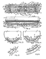
- Heat exchanger unit 30 comprises arcuate top and bottom plates 32 and 34 having a plurality of baffle plates 36 secured thereto and extending therebetween as best illustrated in Fig. 1 to create a plurality of passageways 38 therebetween.
- the peripheries of plates 32 and 34 are secured together and sealed by means of a wall member 40 extending therearound and define therewith a heat exchanger medium containing chamber 43.
- the inner end of wall 40 is curved at 41 so as to conform to the configuration of the upper end of the discharge valve 26.
- the numeral 42 refers to an inlet extending upwardly through the bottom of the tank 14 and in communication with the interior of the heat exchanger as best seen in Figs. 2 and 3.
- Outlet 44 also extends upwardly through the bottom of the tank 14 and is in communication with the interior of the heat exchanger as illustrated in Fig. 2.
- the heat exchanger unit 30 is defined as follows.
- the heat exchanger outer wall 40 has a curved outer end portion 40a, a flat inner end portion 40b with a curved tank outlet surrounding portion 40c, and longitudinally extending flat side portions 40e and 40f that diverge inwardly toward one another.
- the baffle plates or means 36 includes U-shaped outer baffle plate member 33 surrounded by wall 40 and having outer longitudinally extending legs 33a, 33b that diverge outwardly from one another, the outer ends 33c of legs 33a, 33b being spaced away from curved end portion 40a; and laterally extending inner end portion 33d that has a central curved portion 33e going around part of the tank drain 26 and having U-shaped outwardly directed bight portion 33f surrounding the inlet 42.
- the baffle means further includes longitudinally elongated fins or plates 35, 35 adjacent wall portion 40b and connecting with the curved portion 40a and extending short off the inner end portion 33d; a hairpin shaped longitudinally extending central baffle plate 37 having outwardly diverging leg portions 37a, 37a ending short of the outer curved portion 40a and inner curved end portion 37b curved around part of heat exchanger outlet 44; and a shortened central plate 39 that extends in slightly between leg portions 37a, 37a.
- the heat exchanger 32 has the same baffle construction and need not be described further.
- the numerals 46 and 48 refer to tubing provided at the upper surface of the bottom plate 34 to assist in draining the condensate in the heat exchanger unit toward the outlet or discharge 44.
- the baffles 36 are provided with openings 49 at the tubes 46 and 48 to enable the condensate in the passageways to flow through the baffle plates so that the condensate is discharged closely adjacent the outlet 44.
- Bars 50 and 52 are welded to the interior surface of the sides of the tank as seen in Fig. 3.
- Bars or brackets 54 and 56 are secured to the sides of the heat exchanger unit 30 and are welded to the bars 50 and 52 respectively.
- Bar or bracket 54 or 58 is also secured to the outer ends of the heat exchanger unit 30 and is welded to the bar 50 or 52 on the interior surface of the tank head end 20 or 22.
- the conventional tank car 10 may be converted to the heated tank car of this invention by first removing a portion of all of the ends or heads 20 and 22.
- the bars 50 and 52 would then be welded to the interior surfaces of the side walls of the tank.
- the heat exchanger units 30 and 30' are then inserted into the interior of the tank so that the brackets 54 and 56 rest upon the bars 50 and 52 respectively and so that the inner end of the units are positioned adjacent the discharge valve 26.
- the tank bottom 18 would have been previously cut away to provide the inlets and outlets of the heat exchanger to extend downwardly through the bottom 18 of the car.
- the heads 20 and 22 are then replaced in conventional fashion with brackets 54 and 56 then being welded in a continuous fashion to the interior surfaces of tank heads.
- the new brackets 54 and 56 are also welded to the bars 50 and 52.
- the inner ends of the heat exchanger units would also be welded together so that a sealed compartment or dead air space 60 is created below the heat exchanger and the bottom 18.
- a novel heated tank car which provides a more efficient heating of the lading and which eliminates the formation of a "boot" of material at the bottom of the car. It can also be seen that the sloping of the heat exchanger unit and the elements 46 and 48 aid in the prevention of condensate accumulating in the heat exchanger, thereby eliminating the serious problem of corrosion normally associated with prior art devices.
- a further feature of the invention lies in the elimination of the heating medium condensate which forms inside the heat exchanger during the process of heating the lading in the tank car.
- the foregoing feature is illustrated with the following embodiment of the heat exchanger illustrated in Figs. 7 and 8.
- a heat exchanger means 128 comprising a pair of heat exchange units 130, 130. Since both units are identical in construction, only the left portion of the tank 114 is shown supporting one of the heat exchange units 130, 130. Since the heat exchanger 128 is supported by the same means as the heat exchanger unit 28 described in reference to Figs. 1-6, there is no necessity for describing the support structure.
- the heat exchanger unit 130 comprises arcuate top and bottom plates 132 and 134 supporting therebetween a plurality of channels 135 and 137 as defined by baffle means in the form of a corrugated member 139 interposed between the top and bottom arcuate plates 132 and 134.
- the channels do not possess equal cross-sectional areas.
- the channel 135 is smaller than the channel 137, the smaller channels 135 functioning to direct a heating medium (steam) upwardly from an inlet 142 toward a tank head 120 and the larger channel 137 directing the heating medium (steam) downwardly toward inlet 142.
- the heating medium such as steam entering the heat exchanger means 128 through the inlet 142 progresses upwardly through the narrow channel 135 until it reaches heater exchanger curved end portion 140a, at which time, the steam subdivides into two portions which flow along a pair of wide channels 137, 137 until the steam portions reach a minor manifold 141 which directs the steam into narrow channels 135a, 135a.
- the steam upon reaching the curved end portion 140a is redirected thereby into wide channels 137,137a, the steam continuing on its way until it meets an inner wall 143.
- the steam after it leaves the channels 135b, impinges on the curved end portion 140a which redirects the steam along the wide channels 137b, the steam finally completing its passage in a main manifold 145 communicating with the atmosphere through an outlet 144.
- the exiting steam may re-enter a reheating chamber in the steam apparatus (not shown) generating the steam.
- the heated portion of the lading causes the unheated portions of the lading to descend to the bottom to effectively cause mixing or rolling of the lading.
- Such thorough and uniform heating of the lading prepares the lading for faster unloading and prevents the lading being subjected to excessive heat which burns or carmelizes the lading. Similar circulation of lading occurs in the embodiment shown in Figs. 7 and 8.
- the heat exchanger means 128 is provided with feeder lines 147, 149 and 151.
- the flaring out of the passages lines as they proceed out to ends of the tank also enhances flow movements of the steam and condensate and increases faster heating of the lading.
- These feeder lines communicate between the narrow channel 135 and the wide channels 137b, thereby permitting a portion of the steam entering the channel 135 to be directed outwardly into the outermost channels 137b to provide steam quickly for quick heating of the extremities of the heat exchanger with steam to assist in purging the heat exchanger with steam and more quickly warm up the lading.
- the heat exchanger means 128 may be provided with additional feeder lines 147a and 147b, as shown particularly in Fig. 7.
- any condensate that forms in channels 137a and 135b will flow downwardly toward the inner wall 143 and pass through an internal drainage port 153 into the minor manifold 141 to join with additional condensate which is formed in channels 137 and 135a, which additional condensate also flows towards the inner wall 143, and then finally exits through an external drainage port 155 which communicates with the outlet 144.
- the drainage means provide removal of the condensate during application of the steam and adequate gravity drainage of the exchanger means after the tank car has been emptied. Any condensate formed in central channel 135 flows downward below the steam moving upstream and out drainage port 142 and through port 155 to outlet 144.
- the corrugated member 139 is secured to the top arcuate plate 132 and the bottom arcuate plate 134 by appropriate means, such as welding. This ensures that there is no transverse heating medium flow between adjoining channels 135 and 137.
- the feeder lines 147, 149, 151, 147a and 147b may be arranged to pass through the walls forming the various channels. However, in the preferred arrangement, the various feeder lines do not pass through the walls of the channels, but are disposed exteriorly of the channels. Referring to Fig. 8, the feeder lines, for example, feeder lines 147a, are secured exteriorly of the heat exchanger means 128 by being secured underneath the bottom arcuate plate 134. The particular feeder lines 147a extend between and communicate with the channels 135 and 135b.
- a heat exchanger means 228 comprises baffle means having a plurality of spaced narrow channels 235 which are defined by a series of longitudinal half-oval members 235a secured to a top arcuate plate 232 and a bottom arcuate plate 234 and a plurality of wide channels 237 defined by the spaces between adjoining half-oval members 235a. Since the half-oval members 235a do not provide sufficient rigidity to the heat exchanger 228, a pair of longitudinal bars 259 are secured between the top and bottom arcuate plates 232 and 234, respectively.
- the longitudinal bars 259 in conjunction with adjacent half-oval members 235a, define a pair of channels 235b. adjacent each of said longitudinal bars 159.
- the arrangement of the spacing of the narrow channels 235 conducting the steam in upward direction, and the wide channels 237 directing the steam on its return path in a downwardly direction is the same as was described in reference to the embodiment shown in Figs. 7 and 8. For example, as shown in Fig.
- the narrow channels 235 formed by the half-oval members 235a are separated by the wide channels 237 established between the top arcuate plate 232 and the bottom arcuate plate 234 and the adjoining half-oval members 235a, or by the wide channels 235b established between the top arcuate plate 232 and the bottom arcuate plate 234 and the longitudinal bars 159. From the foregoing example, it is obvious that other means may be employed for defining the channels between the top and bottom arcuate plates 232 and 234, respectively.
- the remaining structural details of the embodiment shown in Fig. 9 are the same as those in connection with the embodiment described in Figs. 7 and 8. In other words, the arrangement of the inlet, outlet and drainage ports would be the same.
- Fig. 10 shows a modified structure of a heat exchanger means 328 having a plurality of channels or passageways 338 defined by longitudinal arcuate members 335 adjoining each other and secured to an arcuate plate 332.
- Fig. 11 shows another modified structure of a heat exchanger means wherein heat exchanger means 428 comprises a pair of heat exchanger units 430a and 430b, oppositely disposed with respect to each other to apply heat to the lading between said heat exchanger units.
- heat exchanger units 428 comprises a pair of heat exchanger units 430a and 430b, oppositely disposed with respect to each other to apply heat to the lading between said heat exchanger units.
- the heat exchanger units are insulated from the wall of the tank 414 by means of dead air spaces 460a and 460b.
- Some of the channels are interconnected by feeder lines 447, as previously described in reference to the embodiment shown in Fig. 7.
- Fig. 12 shows a still further modification of a heat exchanger means 528 having a pair of heat exchanger units 530a and 530b adapted to impart heat to a lading inside the tank 514.
- the heat exchanger unit 530a is similar to the heat exchanger units previously described.
- the heat exchanger unit 530b comprises a series of tubes arranged in serpentine fashion on top of the tank 514. The arrangement of the two heat exchanger units 530a and 530b imparts heat to the lading disposed between these heat exchanger units. Some of the channels in the heat exchanger units 530a, 530b are interconnected by feeder lines 557.
- the heat exchanger unit 530b can be permanently mounted on top of the tank 514 for heating lading, such as sulfur, requiring a large input of heat for liquification purposes.
- the heat exchanger unit 530b may be a portable unit which can be placed atop the tank 514, as the occasion demands.
- FIG. 13 The embodiment illustrated in Fig. 13 is secured within a tank 614 which has been provided with additional dead air spaces 660c as defined by upstanding walls 661. These additional dead air spaces 660c cooperate with dead air spaces 660a, 660b to increase heat transfer from heating units ' 630a, 630b to the lading in the tank 614. As in the preceding embodiments,-.feeder lines such as feeder lines 647 interconnect some of the channels in the heating units.
- Fig. 13 shows another way of securing a heat exchanger unit 730a to a tank 714.
- the intermediate members comprising brackets 54, 56 and bars 50, 52, as shown in Fig. 3, these intermediate members can be eliminated by securing the heat exchanger units 730a directly to the tank 714 by appropriate means such as a continuous welding bead 430c which secures the outer periphery of the heating unit to the tank 714.
Landscapes
- Engineering & Computer Science (AREA)
- Mechanical Engineering (AREA)
- Transportation (AREA)
- Heat-Exchange Devices With Radiators And Conduit Assemblies (AREA)
Claims (21)
Applications Claiming Priority (4)
| Application Number | Priority Date | Filing Date | Title |
|---|---|---|---|
| US385869 | 1982-06-07 | ||
| US06/385,869 US4480370A (en) | 1982-06-07 | 1982-06-07 | Heated railroad tank car |
| US454537 | 1982-12-30 | ||
| US06/454,537 US4476788A (en) | 1982-06-07 | 1982-12-30 | Heated railroad tank car |
Publications (3)
| Publication Number | Publication Date |
|---|---|
| EP0110975A1 EP0110975A1 (de) | 1984-06-20 |
| EP0110975A4 EP0110975A4 (de) | 1984-07-06 |
| EP0110975B1 true EP0110975B1 (de) | 1987-07-29 |
Family
ID=27011181
Family Applications (1)
| Application Number | Title | Priority Date | Filing Date |
|---|---|---|---|
| EP83902186A Expired EP0110975B1 (de) | 1982-06-07 | 1983-06-03 | Geheizter eisenbahntankwagen |
Country Status (8)
| Country | Link |
|---|---|
| US (1) | US4476788A (de) |
| EP (1) | EP0110975B1 (de) |
| KR (1) | KR880001962B1 (de) |
| CA (1) | CA1197413A (de) |
| DE (1) | DE3372737D1 (de) |
| IT (1) | IT1171822B (de) |
| MX (1) | MX158559A (de) |
| WO (1) | WO1983004398A1 (de) |
Cited By (1)
| Publication number | Priority date | Publication date | Assignee | Title |
|---|---|---|---|---|
| RU2703603C1 (ru) * | 2018-04-03 | 2019-10-21 | "Головное специализированное конструкторское бюро вагоностроения имени Валерия Михайловича Бубнова" | Вагон-цистерна для затвердевающих и вязких грузов |
Families Citing this family (25)
| Publication number | Priority date | Publication date | Assignee | Title |
|---|---|---|---|---|
| US4530288A (en) * | 1984-02-27 | 1985-07-23 | Loevinger Richard P | Heated railway tank car |
| US4624189A (en) * | 1984-02-27 | 1986-11-25 | Loevinger Richard P | Heated outlet valve for railway tank car |
| US4775070A (en) * | 1987-02-24 | 1988-10-04 | James Williams | System for preventing fluid surges in fluid transport vehicles |
| FR2613057B1 (fr) * | 1987-03-23 | 1989-08-18 | Arbel Fauvet Rail Sa | Procede de chauffage des citernes, moyens en vue de la realisation de ce procede et citernes pourvues de ces moyens |
| DE8706579U1 (de) * | 1987-05-07 | 1988-09-08 | Westerwälder Eisenwerk Gerhard GmbH, 57586 Weitefeld | Temperierbarer Tankcontainer |
| IE60402B1 (en) * | 1987-10-15 | 1994-07-13 | Container Design Ltd | A temperature controllable tank container |
| WO1991001238A1 (en) * | 1989-07-14 | 1991-02-07 | Loevinger Richard P | Heated tank car with discharge valve and pressure equalizer |
| US5058511A (en) * | 1989-07-14 | 1991-10-22 | Loevinger Richard P | Heated tank car with discharge valve and pressure equalizer |
| US5020447A (en) * | 1989-07-14 | 1991-06-04 | Loevinger Richard P | Tank car discharge valve heating unit |
| CH682390A5 (fr) * | 1990-03-09 | 1993-09-15 | Adryx Oil Group Nv | Conteneur pour le transport d'un matériau en état solide. |
| US5706883A (en) * | 1996-08-09 | 1998-01-13 | Jack M. Berry, Inc. | Mass storage and dispensing system for liquids such as citrus products |
| RU2195420C2 (ru) * | 2000-06-30 | 2002-12-27 | Петербургский государственный университет путей сообщения | Цистерна для транспортировки загустевающих жидкостей |
| US6347589B1 (en) * | 2000-06-30 | 2002-02-19 | Trn Business Trust | Railway tank car having a heating system with internal heat transfer panel |
| CA2693685A1 (en) * | 2009-02-18 | 2010-08-18 | L'equipe Fabconcept Inc. | Vehicle frame |
| CA2695907A1 (en) * | 2009-03-05 | 2010-09-05 | Robica-Forman Tank Ltd. | Transformer oil holding assembly |
| US20120247067A1 (en) * | 2011-03-30 | 2012-10-04 | Podd Stephen D | Steam dispersion system for cargo containers |
| CN104326186A (zh) * | 2014-10-24 | 2015-02-04 | 天津新华昌运输设备有限公司 | 一种带有底出料加热装置的罐式集装箱 |
| US10220758B2 (en) * | 2015-02-25 | 2019-03-05 | Recover Energy Services Inc. | Heated drill cuttings transport vessel |
| US10035406B2 (en) * | 2015-02-25 | 2018-07-31 | Recover Energy Services Inc. | Liquid containing drill cuttings transport vessel |
| US12280934B2 (en) * | 2018-02-27 | 2025-04-22 | Liquidpower Specialty Products Inc. | Storage vessel |
| CN110844374B (zh) * | 2019-12-02 | 2025-07-15 | 中车西安车辆有限公司 | 一种用于斜撑结构罐式集装箱的加热套 |
| US12077362B2 (en) | 2021-08-06 | 2024-09-03 | Ryan Peterkin | Transportable self contained cutting box |
| US11772884B2 (en) | 2021-08-06 | 2023-10-03 | Ryan Peterkin | Pressure vessel device |
| US10933794B1 (en) | 2020-10-02 | 2021-03-02 | Magtec Alaska, LLC | Heated slurry transport system |
| CN113685378B (zh) * | 2021-08-07 | 2022-12-20 | 中国航空工业集团公司沈阳飞机设计研究所 | 一种集成式液压油箱 |
Family Cites Families (19)
| Publication number | Priority date | Publication date | Assignee | Title |
|---|---|---|---|---|
| US1412756A (en) * | 1921-01-26 | 1922-04-11 | William B Smith | Tank-car heater |
| US1472488A (en) * | 1921-07-23 | 1923-10-30 | Gen American Tank Car Corp | Tank car |
| US1706084A (en) * | 1926-11-04 | 1929-03-19 | American Car & Foundry Co | Car-tank heater |
| US1914585A (en) * | 1931-05-20 | 1933-06-20 | Union Tank Car Co | Tank heating device |
| FR811010A (fr) * | 1935-12-21 | 1937-04-05 | Dispositif de réchauffage des matières non fluides aux températures ordinaires et emmagasinées dans des réservoirs | |
| US2145614A (en) * | 1937-05-12 | 1939-01-31 | Union Starch And Refining Comp | Heating and insulating means for tank cars |
| US2545371A (en) * | 1946-10-19 | 1951-03-13 | Mojonnier Bros Co | Heat exchange receptacle |
| US2558648A (en) * | 1947-11-01 | 1951-06-26 | Ind Metal Protectives Inc | Apparatus for transporting materials |
| US2624553A (en) * | 1948-01-21 | 1953-01-06 | Gen Am Transport | Heating system for tanks |
| US2772784A (en) * | 1952-12-30 | 1956-12-04 | Gen Foods Corp | Tank for transporting viscous liquids |
| US3143108A (en) * | 1960-06-06 | 1964-08-04 | Lubbock Machine & Supply | System for heating liquid in tanks |
| US3255517A (en) * | 1961-01-26 | 1966-06-14 | Amf Beaird Inc | Method of forming an integral tank shell heat-exchange coil |
| US3176764A (en) * | 1961-01-26 | 1965-04-06 | J B Beaird Company Inc | Integral tank shell heat-exchange coils |
| US3228466A (en) * | 1964-04-24 | 1966-01-11 | Union Tank Car Co | External heating arrangement for a storage tank |
| US3479724A (en) * | 1967-08-01 | 1969-11-25 | Union Tank Car Co | Method of expanding a railway tank car by lengthening same |
| US3503381A (en) * | 1967-11-07 | 1970-03-31 | Union Tank Car Co | Tank car heating system |
| US3595307A (en) * | 1969-09-17 | 1971-07-27 | Gen Am Transport | Storage tank heating arrangement |
| US3685458A (en) * | 1970-06-30 | 1972-08-22 | Gen America Transportation Cor | Railway tank car heating arrangement |
| US3742866A (en) * | 1971-05-17 | 1973-07-03 | Acf Ind Inc | Tank car having sloping bottom |
-
1982
- 1982-12-30 US US06/454,537 patent/US4476788A/en not_active Expired - Lifetime
-
1983
- 1983-05-23 MX MX197387A patent/MX158559A/es unknown
- 1983-05-30 CA CA000429153A patent/CA1197413A/en not_active Expired
- 1983-06-03 KR KR1019830002490A patent/KR880001962B1/ko not_active Expired
- 1983-06-03 WO PCT/US1983/000845 patent/WO1983004398A1/en not_active Ceased
- 1983-06-03 DE DE8383902186T patent/DE3372737D1/de not_active Expired
- 1983-06-03 EP EP83902186A patent/EP0110975B1/de not_active Expired
- 1983-06-06 IT IT48426/83A patent/IT1171822B/it active
Cited By (1)
| Publication number | Priority date | Publication date | Assignee | Title |
|---|---|---|---|---|
| RU2703603C1 (ru) * | 2018-04-03 | 2019-10-21 | "Головное специализированное конструкторское бюро вагоностроения имени Валерия Михайловича Бубнова" | Вагон-цистерна для затвердевающих и вязких грузов |
Also Published As
| Publication number | Publication date |
|---|---|
| EP0110975A1 (de) | 1984-06-20 |
| MX158559A (es) | 1989-02-14 |
| US4476788A (en) | 1984-10-16 |
| KR880001962B1 (ko) | 1988-10-08 |
| IT8348426A0 (it) | 1983-06-06 |
| CA1197413A (en) | 1985-12-03 |
| IT1171822B (it) | 1987-06-10 |
| KR840005036A (ko) | 1984-11-03 |
| WO1983004398A1 (en) | 1983-12-22 |
| EP0110975A4 (de) | 1984-07-06 |
| DE3372737D1 (en) | 1987-09-03 |
Similar Documents
| Publication | Publication Date | Title |
|---|---|---|
| US4476788A (en) | Heated railroad tank car | |
| US4603733A (en) | Heated railroad tank car | |
| US4480370A (en) | Heated railroad tank car | |
| US2655007A (en) | Shell freezer and method of freezing liquids | |
| EP0169361B1 (de) | Verfahren und Anlage zur Pasteurisierung | |
| JPH10150964A (ja) | 食品処理装置 | |
| US4756447A (en) | Temperature-controlled tank container | |
| AU592054B2 (en) | Food processing method and apparatus | |
| US4727800A (en) | Pasteurization apparatus | |
| NZ227581A (en) | Thermal storage unit: heat exchange path extended during supply cycle | |
| RU2379984C2 (ru) | Способ пастеризации продуктов в емкостях и установка для его осуществления | |
| US4635812A (en) | Apparatus for heating pasta and sauce | |
| US2031812A (en) | Method of and apparatus for making ice | |
| US4624189A (en) | Heated outlet valve for railway tank car | |
| US1693249A (en) | Vat | |
| US2624553A (en) | Heating system for tanks | |
| US5058511A (en) | Heated tank car with discharge valve and pressure equalizer | |
| JPH0126948B2 (de) | ||
| US2861514A (en) | Deep fat cooking apparatus | |
| SU1518224A1 (ru) | Устройство дл разгрузки железнодорожных цистерн с застывшими нефтепродуктами | |
| US1891518A (en) | Reenforcement for heat interchangers | |
| US2393387A (en) | Milk cooler | |
| US1893135A (en) | Heat exchange device | |
| US879515A (en) | Apparatus for concentrating liquids. | |
| SU1196663A1 (ru) | Вертикальный кожухотрубный теплообменник |
Legal Events
| Date | Code | Title | Description |
|---|---|---|---|
| PUAI | Public reference made under article 153(3) epc to a published international application that has entered the european phase |
Free format text: ORIGINAL CODE: 0009012 |
|
| AK | Designated contracting states |
Designated state(s): DE FR GB |
|
| 17P | Request for examination filed |
Effective date: 19840519 |
|
| GRAA | (expected) grant |
Free format text: ORIGINAL CODE: 0009210 |
|
| AK | Designated contracting states |
Kind code of ref document: B1 Designated state(s): DE FR GB |
|
| REF | Corresponds to: |
Ref document number: 3372737 Country of ref document: DE Date of ref document: 19870903 |
|
| ET | Fr: translation filed | ||
| PLBE | No opposition filed within time limit |
Free format text: ORIGINAL CODE: 0009261 |
|
| STAA | Information on the status of an ep patent application or granted ep patent |
Free format text: STATUS: NO OPPOSITION FILED WITHIN TIME LIMIT |
|
| 26N | No opposition filed | ||
| PGFP | Annual fee paid to national office [announced via postgrant information from national office to epo] |
Ref country code: FR Payment date: 19910607 Year of fee payment: 9 |
|
| PGFP | Annual fee paid to national office [announced via postgrant information from national office to epo] |
Ref country code: GB Payment date: 19910806 Year of fee payment: 9 |
|
| PG25 | Lapsed in a contracting state [announced via postgrant information from national office to epo] |
Ref country code: GB Effective date: 19920603 |
|
| GBPC | Gb: european patent ceased through non-payment of renewal fee |
Effective date: 19920603 |
|
| PG25 | Lapsed in a contracting state [announced via postgrant information from national office to epo] |
Ref country code: FR Effective date: 19930226 |
|
| REG | Reference to a national code |
Ref country code: FR Ref legal event code: ST |
|
| PGFP | Annual fee paid to national office [announced via postgrant information from national office to epo] |
Ref country code: DE Payment date: 20010523 Year of fee payment: 19 |
|
| PG25 | Lapsed in a contracting state [announced via postgrant information from national office to epo] |
Ref country code: DE Free format text: LAPSE BECAUSE OF NON-PAYMENT OF DUE FEES Effective date: 20030101 |