EP0110946B1 - Verfahren, anlage und anordnung zur kompaktierung von länglichen gegenständen - Google Patents
Verfahren, anlage und anordnung zur kompaktierung von länglichen gegenständen Download PDFInfo
- Publication number
- EP0110946B1 EP0110946B1 EP83901818A EP83901818A EP0110946B1 EP 0110946 B1 EP0110946 B1 EP 0110946B1 EP 83901818 A EP83901818 A EP 83901818A EP 83901818 A EP83901818 A EP 83901818A EP 0110946 B1 EP0110946 B1 EP 0110946B1
- Authority
- EP
- European Patent Office
- Prior art keywords
- objects
- bundle
- guiding tubes
- assembly
- tubes
- Prior art date
- Legal status (The legal status is an assumption and is not a legal conclusion. Google has not performed a legal analysis and makes no representation as to the accuracy of the status listed.)
- Expired
Links
Images


Classifications
-
- G—PHYSICS
- G21—NUCLEAR PHYSICS; NUCLEAR ENGINEERING
- G21C—NUCLEAR REACTORS
- G21C19/00—Arrangements for treating, for handling, or for facilitating the handling of, fuel or other materials which are used within the reactor, e.g. within its pressure vessel
- G21C19/34—Apparatus or processes for dismantling nuclear fuel, e.g. before reprocessing ; Apparatus or processes for dismantling strings of spent fuel elements
-
- Y—GENERAL TAGGING OF NEW TECHNOLOGICAL DEVELOPMENTS; GENERAL TAGGING OF CROSS-SECTIONAL TECHNOLOGIES SPANNING OVER SEVERAL SECTIONS OF THE IPC; TECHNICAL SUBJECTS COVERED BY FORMER USPC CROSS-REFERENCE ART COLLECTIONS [XRACs] AND DIGESTS
- Y02—TECHNOLOGIES OR APPLICATIONS FOR MITIGATION OR ADAPTATION AGAINST CLIMATE CHANGE
- Y02E—REDUCTION OF GREENHOUSE GAS [GHG] EMISSIONS, RELATED TO ENERGY GENERATION, TRANSMISSION OR DISTRIBUTION
- Y02E30/00—Energy generation of nuclear origin
- Y02E30/30—Nuclear fission reactors
-
- Y—GENERAL TAGGING OF NEW TECHNOLOGICAL DEVELOPMENTS; GENERAL TAGGING OF CROSS-SECTIONAL TECHNOLOGIES SPANNING OVER SEVERAL SECTIONS OF THE IPC; TECHNICAL SUBJECTS COVERED BY FORMER USPC CROSS-REFERENCE ART COLLECTIONS [XRACs] AND DIGESTS
- Y10—TECHNICAL SUBJECTS COVERED BY FORMER USPC
- Y10T—TECHNICAL SUBJECTS COVERED BY FORMER US CLASSIFICATION
- Y10T29/00—Metal working
- Y10T29/53—Means to assemble or disassemble
- Y10T29/531—Nuclear device
Definitions
- the present invention relates to a method, an installation and a device for compacting oblong and flexible objects, in particular nuclear reactor fuel rods.
- the fissile material consists of uranium oxide pellets stacked in metal sheaths closed at each end, to form what are called "fuel rods". These are collected in large numbers (for example 264), with a certain number of tubes not containing fuel, to form a combustible element. The fuel elements are placed in the reactor to form the core thereof.
- the irradiated fuel elements are removed from the reactor and immersed for several months in a nearby swimming pool in order to cool and lose most of their radioactivity. Then, they are evacuated to an appropriate site and stored in one way or another (swimming pool, storage packaging, etc.) pending their possible reprocessing.
- the fuel rods For transport as for storage, it is interesting, to save space, to dismantle the fuel elements and to gather, in a compact way, the fuel rods in bundles, that is to say in a more or less whole compact of oblong objects, rectilinear and parallel to each other over their entire length.
- the fuel rods which have, for example, an outside diameter of the order of 9.5 mm, are arranged in a square mesh network of the order of 12 , 6 mm side. This results in a cross section of the fuel element close to twice that of a compact network.
- the subject of the present invention is a method, an installation and a device making it possible to compact objects of great length and small transverse dimensions in order to arrange them reliably, repetitively and quickly in a container, so that the portion of the section thereof occupied by the cross sections of said objects is maximum. It applies very particularly, although not exclusively, to the handling and compacting of fuel rods with a view to their placing in containers, whatever the purpose of this placing in containers (final storage, intermediate storage, transport, etc.) .
- the invention relates to a method for compacting a bundle of oblong and flexible objects of small transverse dimensions, such as fuel rods for nuclear reactors, said objects constituting, prior to compacting, an assembly in which they occupy positions parallel, transversely spaced, according to claim 1.
- said tubes can be arranged in any general direction desired, it is advantageous, to take advantage of gravity, that this direction is substantially vertical.
- the upper ends of the guide tubes are arranged in accordance with the initial arrangement of said set of objects and the lower ends of said tubes are arranged according to the desired arrangement; and said assembly is brought vertically above the plurality of guide tubes and, after introduction of said objects into said tubes, said objects are allowed to slide down under the action of gravity.
- the desired arrangement of the objects is obtained, which can be either more compact or less compact than the initial arrangement of said objects.
- the degree of compaction of the objects, obtained at the outlet of the plurality of tubes depends on the arrangement and the thickness of wall of said tubes at their lower part.
- the plurality of guide tubes are given the most constricted arrangement possible in their lower part and are arranged downstream of these a plurality of elongate and rigid guide elements whose ends directed towards the guide tubes are located opposite the interstices situated between the constricted ends thereof and whose opposite ends are housed in the interstices left free between said objects, when these are in contact with each other.
- Each of said guide elements may consist of a wire, the set of wires forming a sort of converging cage.
- said elements can be formed by a thick plate or a multitude of superimposed plates in which are guided guide holes, the material remaining between said holes constituting said guide elements.
- said guide elements make it possible to compact objects transversely as much as possible.
- a compacting device comprising a plurality of guide tubes, the ends of which on one side are arranged in accordance with the initial arrangement of the assembly of objects to be compacted and, on the other side, the ends are arranged in the desired arrangement, the dimensions of said guide tubes being such that in each of them can freely slide one of said objects.
- the tubes are made integral with one another by means of transverse flanges pierced with holes arranged respectively in accordance with the arrangements adopted for the ends of the tubes.
- said compacting device On the narrower downstream side, said compacting device is extended by a plurality of rigid guide elements integral with the corresponding flange and arranged so as to be housed, on the side of said flange, in the interstices located between the ends of the guide tubes and, on the side opposite the flange, in the gaps left free between said objects gathered in a bundle.
- peripheral wires are made integral with a closed bearing surface reproducing the outline of the straight beam section at the tightest point.
- this container can be placed as an extension of the plurality of tubes and the guide elements, downstream of these, then slide the objects at the inside said container.
- this approach has the disadvantage of requiring a large longitudinal space, since at a time the objects are in extension of the plurality of tubes and guide elements which are themselves in extension of the container.
- the containerization of fuel rods carried out vertically in a cooling and deactivation pool it is impossible to operate in this way, because then the fuel rods would at some time be too close to the surface of the pool water.
- a device for temporarily receiving oblong objects there is, downstream of the plurality of guide elements and in extension thereof, a device for temporarily receiving oblong objects, this device being extendable, retractable and susceptible to keep said objects in a bundle, the beam of objects from the plurality of guide tubes is transferred to the temporary reception device, by moving said plurality of guide tubes away and progressively deploying said temporary reception device towards the tubes guidance, and then proceeds to the transfer of the boot of objects from the provisional receiving device to the container by pushing the latter coaxially with said boot, while gradually retracting said provisional receiving device.
- an advantageous installation for implementing the method according to the invention comprises a plurality of guide tubes, arranged in a generally vertical direction, the upper ends of which are arranged in accordance with the initial arrangement of said set of objects, and whose the lower ends are arranged in the desired arrangement, the dimensions of said guide tubes being such that in each of them can slide freely one of said objects under the action of gravity.
- the installation is provided for the removal from a first container of a set of objects occupying parallel, transversely spaced positions, as well as for placing in a second container the more or less compact boot obtained at starting from said assembly, it then comprises gripping and handling means for pulling by lifting out of the first container, arranged vertically, said set of objects, then for introducing the lower ends of said objects into the upper ends of said plurality of tubes guide, as well as means for transferring said bundle of objects from the plurality of tubes to the second container.
- the references used (from 1 to 21) have the same meaning everywhere.
- the invention has been illustrated with the aid of a particular embodiment intended for compacting the 264 rods of a conventional fuel element for a nuclear reactor.
- the compacting device 1 comprises a plurality of tubes 2 (for example 66) spaced from each other at their upper ends and in contact with each other at their lower ends.
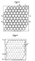
- the upper ends 2a of the tubes are made integral with the lower face of a thick plate or flange 3, the surface of which is substantially equal to the section of a combustible element, in which through holes are drilled, flared towards the outside, that is to say on the side opposite the tubes 2 (see figs. 2 and 3).
- the relative arrangement of the 66 holes 4 of the flange 3 is such that if the flange 3 was rotated, by four successive quarter turns around its center 5, the 66 holes 4 would occupy the 264 locations of the pencils of the fuel element.
- all of the 264 pencils are sampled in four samples, and at each sample, the rods taken out of the fuel element can be inserted into the holes 4 without difficulty, since they have the same relative arrangement as these.
- the lower ends 2b of the tubes 2 are made integral with the upper face of a plate or flange 6, in which holes are drilled 7. There are as many holes 7 as tubes 2 and each of these is extended by one of said holes. As shown in fig. 4, each hole 7 (except on the edges) is surrounded by six holes 7 which are adjacent to it.
- the tubes 2 pass from a spaced arrangement with a square mesh (at the level of the flange 3) to a tight arrangement with a hexagonal mesh (at the level of the flange 6).
- rigid wires 8 are fixed to the underside of the flange 6, in the interstices situated between the ends 2b of the tubes 2, in order to extend said tubes as immaterially as possible by converging towards each other until define the outer contour of each of the fuel rods.
- the wires 8 are protected by a plate 9 (see fig. 5) inside which a cutout 9a is made corresponding to the section of a compact bundle of 66 pencils.
- the ends of the peripheral wires 8 are made integral with the plate 9, the others being inside the cutout 9a.
- the degree of compaction obtained downstream of the flange 6 depends on the outside diameter, therefore on the wall thickness, of the tubes 2 at their lower end 2b.
- the rigid wires 8 make it possible to perfect the compaction.
- the compaction gradient, and therefore the length of the tubes 2 depend on the flexibility of the rods and the clearance between the internal diameter of the tubes 2 and the rods. Experience has shown that, for conventional pencils 4 m in length and 9.5 mm in diameter, tubes with a length of 2, 5 to 3 m and 10.5 mm in internal diameter extended by wires about 0.5 m in length gave good results.
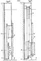
- FIGS. 6 to 9 schematically illustrate an application of the method according to the invention, FIGS. 8 and 9 showing a view at 90 ° relative to that of FIGS. 6 and 7.
- This intermediate receiving device 15 comprises a plurality of plates 16 parallel to each other and identical to the plate 9 of the device 1.
- the different plates 16 can move vertically, remaining horizontal, along vertical rails 17. In the position shown in fig. 6 and 7, the compacting device 1 is located between the rails 17 and the plates 16 are in their low position.
- a combustible element 18 is vertically centered on the turntable 12.
- the mechanism 13 (shown in FIGS. 6 and 7) makes it possible to operate a device 19 for extracting the rods 20 from the combustible element 18.
- the device 19 is brought by the mechanism 13 above the element 18 and takes therefrom 66 pencils distributed in accordance with FIG. 2 (see fig. 6). Then the mechanism 13 moves the device 19 to bring it in line with the device 1. The 66 rods descend vertically and, after passing through the device 1 by the action of gravity, they are compacted and are released. The bundle of pencils 20 at the outlet of the device 1 crosses the various plates 16 assembled (see FIG. 7). The mechanism 14 is then actuated to raise the device 1, in order to remove it from between the rails 17, while the plates 16 are also maneuvered so that, sliding upwards, they separate from one another. Thus, the device 1 releases the rods 20 which are however kept compacted by the spaced plates 16 (see FIG. 8). Finally, the mechanism 14 brings the container 21 which is lowered so that it is perpendicular to the bundle of pencils contained in the intermediate receiving device 15. that the compacted pencils 20 pass through said container 21 (see FIG. 9).
Landscapes
- Physics & Mathematics (AREA)
- Engineering & Computer Science (AREA)
- Plasma & Fusion (AREA)
- General Engineering & Computer Science (AREA)
- High Energy & Nuclear Physics (AREA)
- Monitoring And Testing Of Nuclear Reactors (AREA)
Claims (10)
Priority Applications (1)
| Application Number | Priority Date | Filing Date | Title |
|---|---|---|---|
| AT83901818T ATE24790T1 (de) | 1982-06-07 | 1983-06-06 | Verfahren, anlage und anordnung zur kompaktierung von laenglichen gegenstaenden. |
Applications Claiming Priority (2)
| Application Number | Priority Date | Filing Date | Title |
|---|---|---|---|
| FR8209859A FR2528218A1 (fr) | 1982-06-07 | 1982-06-07 | Procede, installation et dispositif pour le compactage d'objets oblongs et flexibles notamment des crayons combustibles de reacteur nucleaire |
| FR8209859 | 1982-06-07 |
Publications (2)
| Publication Number | Publication Date |
|---|---|
| EP0110946A1 EP0110946A1 (de) | 1984-06-20 |
| EP0110946B1 true EP0110946B1 (de) | 1987-01-07 |
Family
ID=9274692
Family Applications (1)
| Application Number | Title | Priority Date | Filing Date |
|---|---|---|---|
| EP83901818A Expired EP0110946B1 (de) | 1982-06-07 | 1983-06-06 | Verfahren, anlage und anordnung zur kompaktierung von länglichen gegenständen |
Country Status (6)
| Country | Link |
|---|---|
| US (1) | US4671921A (de) |
| EP (1) | EP0110946B1 (de) |
| JP (1) | JPS59501331A (de) |
| DE (1) | DE3369025D1 (de) |
| FR (1) | FR2528218A1 (de) |
| WO (1) | WO1983004454A1 (de) |
Families Citing this family (14)
| Publication number | Priority date | Publication date | Assignee | Title |
|---|---|---|---|---|
| US4943410A (en) * | 1981-08-10 | 1990-07-24 | U.S. Tool & Die, Inc. | Compaction apparatus for spent nuclear fuel rods |
| US4704247A (en) * | 1981-08-10 | 1987-11-03 | U.S. Tool & Die Co., Inc. | Method and apparatus for compacting spent nuclear reactor fuel rods |
| US4547117A (en) * | 1983-09-23 | 1985-10-15 | Westinghouse Electric Corp. | Nuclear fuel rod bundle drive apparatus |
| US4659535A (en) * | 1984-12-24 | 1987-04-21 | Combustion Engineering, Inc. | Grid structure for fuel rod consolidation canister |
| EP0186161A3 (de) * | 1984-12-24 | 1987-12-02 | Combustion Engineering, Inc. | Befestigungsschachtel für Kernbrennstoffstäbe |
| DE3506584A1 (de) * | 1985-02-25 | 1986-08-28 | Kraftwerk Union AG, 4330 Mülheim | Einrichtung zum einsetzen von kernbrennstoff oder neutronenabsorberstoff enthaltenden staeben in einer vorgegebenen dichten packung in einen behaelter |
| FR2586854B1 (fr) * | 1985-08-29 | 1987-12-04 | Framatome Sa | Procede et dispositif de compactage d'un faisceau de crayons de combustibles |
| FR2596565B1 (fr) * | 1986-04-01 | 1988-07-01 | Cogema | Procede de mise en etui d'un faisceau de crayons d'un assemblage de combustible nucleaire et installation pour la mise en oeuvre de ce procede |
| FR2600202A1 (fr) * | 1986-06-12 | 1987-12-18 | Transnucleaire | Dispositif modulaire de compactage sous eau d'assemblages combustibles nucleaires |
| US4822554A (en) * | 1986-10-08 | 1989-04-18 | Westinghouse Electric Corp. | Reconstitution and repair system for nuclear fuel rod assemblies |
| DE3711844A1 (de) * | 1987-04-08 | 1988-10-27 | Wiederaufarbeitung Von Kernbre | Vorrichtung zum herausziehen von mehreren brennstaeben aus einem brennelement |
| US5000906A (en) * | 1987-06-18 | 1991-03-19 | Westinghouse Electric Corp. | System and method for removing and consolidating the fuel rods of a nuclear fuel assembly |
| US4952072A (en) * | 1987-06-18 | 1990-08-28 | Westinghouse Electric Corp. | System and method for removing and consolidation fuel rods of a nuclear fuel assembly |
| FR2642219B1 (de) * | 1989-01-23 | 1994-03-18 | Commissariat A Energie Atomique |
Family Cites Families (9)
| Publication number | Priority date | Publication date | Assignee | Title |
|---|---|---|---|---|
| LU78579A1 (de) * | 1976-11-27 | 1978-04-20 | ||
| US4158601A (en) * | 1977-05-12 | 1979-06-19 | Westinghouse Electric Corp. | Nuclear fuel pellet loading apparatus |
| SE409627B (sv) * | 1978-01-24 | 1979-08-27 | Asea Atom Ab | Sett att anbringa brenslekutsar i kapslingsror vid framstellning av kernbrenslestavar jemte utrustning for genomforande av settet |
| US4441242A (en) * | 1981-05-29 | 1984-04-10 | Westinghouse Electric Corp. | Spent fuel consolidation system |
| EP0066695B1 (de) * | 1981-05-29 | 1986-01-22 | Westinghouse Electric Corporation | Kompaktierungssystem für verbrauchten Kernbrennstoff |
| US4446098A (en) * | 1981-05-29 | 1984-05-01 | Westinghouse Electric Corp. | Spent fuel consolidation system |
| US4511499A (en) * | 1982-03-18 | 1985-04-16 | Westinghouse Electric Corp. | Apparatus for dismantling and disposing of fuel assemblies |
| US4548347A (en) * | 1982-11-30 | 1985-10-22 | The United States Of America As Represented By The United States Department Of Energy | Automated fuel pin loading system |
| US4537741A (en) * | 1982-11-30 | 1985-08-27 | The United States Of America As Represented By The United States Department Of Energy | Funnel for fuel pin loading system |
-
1982
- 1982-06-07 FR FR8209859A patent/FR2528218A1/fr active Granted
-
1983
- 1983-06-06 WO PCT/FR1983/000110 patent/WO1983004454A1/fr not_active Application Discontinuation
- 1983-06-06 US US06/576,383 patent/US4671921A/en not_active Expired - Fee Related
- 1983-06-06 EP EP83901818A patent/EP0110946B1/de not_active Expired
- 1983-06-06 DE DE8383901818T patent/DE3369025D1/de not_active Expired
- 1983-06-06 JP JP58502027A patent/JPS59501331A/ja active Pending
Also Published As
| Publication number | Publication date |
|---|---|
| EP0110946A1 (de) | 1984-06-20 |
| DE3369025D1 (en) | 1987-02-12 |
| WO1983004454A1 (fr) | 1983-12-22 |
| FR2528218A1 (fr) | 1983-12-09 |
| FR2528218B1 (de) | 1985-02-15 |
| US4671921A (en) | 1987-06-09 |
| JPS59501331A (ja) | 1984-07-26 |
Similar Documents
| Publication | Publication Date | Title |
|---|---|---|
| EP0110946B1 (de) | Verfahren, anlage und anordnung zur kompaktierung von länglichen gegenständen | |
| FR2521763A1 (fr) | Appareil et procede pour enlever et remplacer des barres de combustible dans un assemblage combustible nucleaire | |
| EP0109902A1 (de) | Vorrichtung zur Wiederherstellung von Brennstoffanordnungen | |
| BE897757A (fr) | Dispositif de prehension pour retirer simultanement une multiplicite de barres de combustible d'un assemblage combustible nucleaire | |
| EP0773554B1 (de) | Einrichtung und Verfahren zum gemeinsamen Lagern von Kernbrennstabbündeln und Steuerstäben | |
| EP0218494B1 (de) | Verfahren und Vorrichtung zur Kompaktierung eines Brennstabbündels | |
| FR2615028A1 (fr) | Appareil et procede pour le charge ment de barres de combustible dans les grilles d'assemblages combustibles nucleaires | |
| EP0347312B1 (de) | Vorrichtung zum Schneiden eines Stabbündels | |
| EP1570492B1 (de) | Verfahren und vorrichtung zum laden eines brennstabbündels in die spaltzone eines kernreaktors | |
| EP0244278B1 (de) | Verfahren zum Einsetzen eines Stabbündels eines Kernbrennstoffbündels in einen Behälter und Anlage zur Durchführung dieses Verfahrens | |
| FR2519178A1 (fr) | Faisceau d'elements combustibles avec barres absorbantes | |
| EP0098781B1 (de) | Einrichtung zur Nachprüfung des Ausschaltens der Steuerbündel eines Kernreaktors | |
| EP0128785B1 (de) | Struktur und Gesamtheit von Mitteln zum Aufstellen von nuklearen Brennstoffelementen | |
| EP0346233B1 (de) | Verfahren zum Verdichten des Skeletts einer nuklearen brennbaren Zusammenstellung | |
| EP0528736B1 (de) | Vorrichtung zum Transfer von Scheiben, insbesondere Silicon-Scheiben | |
| FR2520150A1 (fr) | Dispositif pour transferer horizontalement entre deux enceintes des elements combustibles nucleaires stockes en position verticale | |
| FR2600202A1 (fr) | Dispositif modulaire de compactage sous eau d'assemblages combustibles nucleaires | |
| FR2582438A1 (fr) | Hotte de manutention et de transport d'assemblages de combustible nucleaire et installation comportant une hotte de ce type | |
| EP1243001B1 (de) | Vorrichtung zur reinigung eines kernreaktor-brennelements | |
| EP0758130B1 (de) | Verfahren und Vorrichtung zur Aufbewahrung benutzter Kontrollstäbe von Kernreaktoren | |
| FR2618014A1 (fr) | Procede et installation de reconstitution d'assemblage combustible nucleaire | |
| EP0587460B1 (de) | Halterungskorb für Elemente einer bearbeiteten Barriere und Greifer zum Hantieren dieses Korbes | |
| FR2543350A1 (fr) | Structure et procede de stockage d'elements combustibles irradies | |
| EP4156206A1 (de) | Zerlegungssystem für kerntechnische anlage | |
| FR2676140A1 (fr) | Dispositif d'insertion d'une capsule d'irradiation dans un panier solidaire des equipements internes d'un reacteur nucleaire. |
Legal Events
| Date | Code | Title | Description |
|---|---|---|---|
| PUAI | Public reference made under article 153(3) epc to a published international application that has entered the european phase |
Free format text: ORIGINAL CODE: 0009012 |
|
| 17P | Request for examination filed |
Effective date: 19840201 |
|
| AK | Designated contracting states |
Designated state(s): AT BE CH DE GB LI LU NL SE |
|
| GRAA | (expected) grant |
Free format text: ORIGINAL CODE: 0009210 |
|
| AK | Designated contracting states |
Kind code of ref document: B1 Designated state(s): AT BE CH DE GB LI LU NL SE |
|
| PG25 | Lapsed in a contracting state [announced via postgrant information from national office to epo] |
Ref country code: AT Effective date: 19870107 |
|
| REF | Corresponds to: |
Ref document number: 24790 Country of ref document: AT Date of ref document: 19870115 Kind code of ref document: T |
|
| REF | Corresponds to: |
Ref document number: 3369025 Country of ref document: DE Date of ref document: 19870212 |
|
| PG25 | Lapsed in a contracting state [announced via postgrant information from national office to epo] |
Ref country code: LU Free format text: LAPSE BECAUSE OF NON-PAYMENT OF DUE FEES Effective date: 19870630 |
|
| PLBI | Opposition filed |
Free format text: ORIGINAL CODE: 0009260 |
|
| 26 | Opposition filed |
Opponent name: SIEMENS AKTIENGESELLSCHAFT, BERLIN UND MUENCHEN Effective date: 19871006 |
|
| NLR1 | Nl: opposition has been filed with the epo |
Opponent name: SIEMENS AKTIENGESELLSCHAFT, BERLIN UND MUENCHEN |
|
| PG25 | Lapsed in a contracting state [announced via postgrant information from national office to epo] |
Ref country code: NL Effective date: 19880101 |
|
| NLV4 | Nl: lapsed or anulled due to non-payment of the annual fee | ||
| PG25 | Lapsed in a contracting state [announced via postgrant information from national office to epo] |
Ref country code: GB Effective date: 19880606 |
|
| PG25 | Lapsed in a contracting state [announced via postgrant information from national office to epo] |
Ref country code: SE Effective date: 19880607 |
|
| BERE | Be: lapsed |
Owner name: SOC. POUR LES TRANSPORTS DE L'INDUSTRIE NUCLEAIRE Effective date: 19880630 |
|
| GBPC | Gb: european patent ceased through non-payment of renewal fee | ||
| REG | Reference to a national code |
Ref country code: CH Ref legal event code: PL |
|
| PG25 | Lapsed in a contracting state [announced via postgrant information from national office to epo] |
Ref country code: DE Effective date: 19890301 |
|
| PG25 | Lapsed in a contracting state [announced via postgrant information from national office to epo] |
Ref country code: BE Effective date: 19890630 |
|
| RDAG | Patent revoked |
Free format text: ORIGINAL CODE: 0009271 |
|
| STAA | Information on the status of an ep patent application or granted ep patent |
Free format text: STATUS: PATENT REVOKED |
|
| 27W | Patent revoked |
Effective date: 19890918 |
|
| GBPR | Gb: patent revoked under art. 102 of the ep convention designating the uk as contracting state | ||
| EUG | Se: european patent has lapsed |
Ref document number: 83901818.1 Effective date: 19890112 |