EP0109902A1 - Vorrichtung zur Wiederherstellung von Brennstoffanordnungen - Google Patents
Vorrichtung zur Wiederherstellung von Brennstoffanordnungen Download PDFInfo
- Publication number
- EP0109902A1 EP0109902A1 EP83402208A EP83402208A EP0109902A1 EP 0109902 A1 EP0109902 A1 EP 0109902A1 EP 83402208 A EP83402208 A EP 83402208A EP 83402208 A EP83402208 A EP 83402208A EP 0109902 A1 EP0109902 A1 EP 0109902A1
- Authority
- EP
- European Patent Office
- Prior art keywords
- tool
- assembly
- clamp
- centering
- installation according
- Prior art date
- Legal status (The legal status is an assumption and is not a legal conclusion. Google has not performed a legal analysis and makes no representation as to the accuracy of the status listed.)
- Granted
Links
- 239000003758 nuclear fuel Substances 0.000 title claims description 3
- 238000009434 installation Methods 0.000 claims abstract description 41
- 239000000446 fuel Substances 0.000 claims abstract description 17
- 230000000712 assembly Effects 0.000 claims abstract description 7
- 238000000429 assembly Methods 0.000 claims abstract description 7
- 230000009182 swimming Effects 0.000 claims abstract description 7
- 239000002131 composite material Substances 0.000 claims description 10
- 238000013519 translation Methods 0.000 claims description 8
- 210000000078 claw Anatomy 0.000 claims description 7
- 238000003780 insertion Methods 0.000 claims description 7
- 230000037431 insertion Effects 0.000 claims description 7
- 241000269799 Perca fluviatilis Species 0.000 claims 1
- 230000002093 peripheral effect Effects 0.000 claims 1
- 230000001681 protective effect Effects 0.000 claims 1
- 238000010079 rubber tapping Methods 0.000 claims 1
- 230000008439 repair process Effects 0.000 abstract description 6
- 238000010586 diagram Methods 0.000 description 15
- 208000031968 Cadaver Diseases 0.000 description 10
- 238000000605 extraction Methods 0.000 description 8
- 230000014616 translation Effects 0.000 description 7
- 230000002950 deficient Effects 0.000 description 5
- 239000000523 sample Substances 0.000 description 5
- 230000007246 mechanism Effects 0.000 description 4
- 230000000903 blocking effect Effects 0.000 description 3
- 238000006073 displacement reaction Methods 0.000 description 3
- 125000006850 spacer group Chemical group 0.000 description 3
- 238000013459 approach Methods 0.000 description 2
- 238000002788 crimping Methods 0.000 description 2
- 230000000694 effects Effects 0.000 description 2
- 238000000034 method Methods 0.000 description 2
- 230000000284 resting effect Effects 0.000 description 2
- 230000000717 retained effect Effects 0.000 description 2
- 239000002915 spent fuel radioactive waste Substances 0.000 description 2
- 229910001220 stainless steel Inorganic materials 0.000 description 2
- 239000010935 stainless steel Substances 0.000 description 2
- 238000012546 transfer Methods 0.000 description 2
- 238000012795 verification Methods 0.000 description 2
- XLYOFNOQVPJJNP-UHFFFAOYSA-N water Substances O XLYOFNOQVPJJNP-UHFFFAOYSA-N 0.000 description 2
- 238000003466 welding Methods 0.000 description 2
- 241000239290 Araneae Species 0.000 description 1
- 230000009471 action Effects 0.000 description 1
- 230000005540 biological transmission Effects 0.000 description 1
- 230000006835 compression Effects 0.000 description 1
- 238000007906 compression Methods 0.000 description 1
- 239000000470 constituent Substances 0.000 description 1
- 238000011161 development Methods 0.000 description 1
- 230000003100 immobilizing effect Effects 0.000 description 1
- 230000036961 partial effect Effects 0.000 description 1
- 230000008569 process Effects 0.000 description 1
- 210000003456 pulmonary alveoli Anatomy 0.000 description 1
- 230000002441 reversible effect Effects 0.000 description 1
- 230000007704 transition Effects 0.000 description 1
Images


Classifications
-
- G—PHYSICS
- G21—NUCLEAR PHYSICS; NUCLEAR ENGINEERING
- G21C—NUCLEAR REACTORS
- G21C17/00—Monitoring; Testing ; Maintaining
- G21C17/06—Devices or arrangements for monitoring or testing fuel or fuel elements outside the reactor core, e.g. for burn-up, for contamination
-
- G—PHYSICS
- G21—NUCLEAR PHYSICS; NUCLEAR ENGINEERING
- G21C—NUCLEAR REACTORS
- G21C3/00—Reactor fuel elements and their assemblies; Selection of substances for use as reactor fuel elements
- G21C3/30—Assemblies of a number of fuel elements in the form of a rigid unit
-
- G—PHYSICS
- G21—NUCLEAR PHYSICS; NUCLEAR ENGINEERING
- G21C—NUCLEAR REACTORS
- G21C3/00—Reactor fuel elements and their assemblies; Selection of substances for use as reactor fuel elements
- G21C3/30—Assemblies of a number of fuel elements in the form of a rigid unit
- G21C3/32—Bundles of parallel pin-, rod-, or tube-shaped fuel elements
- G21C3/335—Exchanging elements in irradiated bundles
-
- Y—GENERAL TAGGING OF NEW TECHNOLOGICAL DEVELOPMENTS; GENERAL TAGGING OF CROSS-SECTIONAL TECHNOLOGIES SPANNING OVER SEVERAL SECTIONS OF THE IPC; TECHNICAL SUBJECTS COVERED BY FORMER USPC CROSS-REFERENCE ART COLLECTIONS [XRACs] AND DIGESTS
- Y02—TECHNOLOGIES OR APPLICATIONS FOR MITIGATION OR ADAPTATION AGAINST CLIMATE CHANGE
- Y02E—REDUCTION OF GREENHOUSE GAS [GHG] EMISSIONS, RELATED TO ENERGY GENERATION, TRANSMISSION OR DISTRIBUTION
- Y02E30/00—Energy generation of nuclear origin
- Y02E30/30—Nuclear fission reactors
-
- Y—GENERAL TAGGING OF NEW TECHNOLOGICAL DEVELOPMENTS; GENERAL TAGGING OF CROSS-SECTIONAL TECHNOLOGIES SPANNING OVER SEVERAL SECTIONS OF THE IPC; TECHNICAL SUBJECTS COVERED BY FORMER USPC CROSS-REFERENCE ART COLLECTIONS [XRACs] AND DIGESTS
- Y10—TECHNICAL SUBJECTS COVERED BY FORMER USPC
- Y10T—TECHNICAL SUBJECTS COVERED BY FORMER US CLASSIFICATION
- Y10T29/00—Metal working
- Y10T29/49—Method of mechanical manufacture
- Y10T29/49815—Disassembling
Definitions
- the subject of the present invention is an installation making it possible to repair nuclear fuel assemblies of the type comprising a skeleton formed by two end pieces connected by tie rods removably attached to the upper end piece at least and grids distributed between the end pieces and intended for maintain a bundle of fuel rods trapped between the ends.
- nuclear fuel assemblies of this type mention may be made of that described and claimed in document FR-A-2 368 785.
- the present invention aims, on the contrary, to provide an installation making it possible to repair a fuel assembly without imposing on it other displacements than horizontal or vertical translations, while guaranteeing precise and reliable positioning of the components during reassembly.
- the invention notably proposes an instal lation comprising a cell movable vertically in a swimming pool and provided, at its upper part, with a base plate having an opening for passage of an assembly and equipped with means for clamping the upper part of the assembly, generally at the level of the upper grid thereof, a guide or centering body designed to be manipulated by a handling tool, intended to cover the upper end of the assembly and to lock on it, and means for separating the tie rods of the upper nozzle.
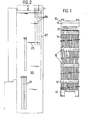
- This assembly 10 shown in FIG. 1, comprises a bundle of fuel rods 11 held by spacer grids 12 distributed along the bundle.
- the grids 12 provide passages, most of which are crossed by fuel rods, while the others are crossed by tie rods 15 fixed to a lower end piece 13 and an upper end piece 14 having at its upper part a shape allowing it to be grasped at using a handling tool.
- the tie rods 15 are fixed to the upper end piece 14 by removable means, constituted by sockets (not visible in FIG. 1) having a threaded lower part intended to be screwed into the upper part of a tie rod and a head. support on the nozzle 14.
- the installation is intended to allow disassembly, repair and reassembly of a fuel assembly while the latter is immersed in water to a depth sufficient to ensure biological protection.
- the installation will generally be mounted on the pit of the spent fuel evacuation pool from a nuclear reactor.
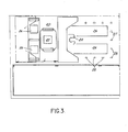
- the installation placed in a swimming pool 20, comprises at least one cell 21, constituted by a container of elongated parallelepiped shape open at its upper end, attached to a support 23 resting on the bottom of the pool.
- This support is provided with means making it possible to vertically move the cell between a low position (in solid lines in FIG. 2) and a high position (in broken lines), offset from the previous one by several meters.
- a mobile traveling crane over distance 1 (FIG. 3) making it possible to move a carriage 22 provided with a tool holder in two perpendicular directions.
- the support 23 is also provided with receptacles 24 and 25 respectively intended for new pencils and for damaged pencils extracted from the assembly.
- the support 23 is provided with various tool storage surfaces lage and of places intended to receive the various tools, which one can dissociate into tools. short 28 (for intervention on the assembly when the cell is in the high position) and long tools 27 (such as the pencil extraction tool).
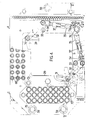
- the head plate A shown in FIGS. 4 and 5, is constituted by a sole 30 in which is formed an opening 29 of sufficient size to allow passage to the assembly when the latter is brought above the cell located at low position, then lowered by a gripper also usable for grabbing and move the guide body B ( Figure 6).
- the sole 30 carries means for clamping the assembly at its upper grid 12, making it possible to hold this assembly in position during removal and after the removal of the upper end piece.
- These means comprise two articulated arms making it possible to bring together and separate from one another two vee plates 31 and to enclose or release two opposite dihedrons from the assembly.
- These articulated arms comprise, from each vee 31, a lever 32 rotating on an axis 33.
- the end of the lever opposite to that which carries the vee is connected by a pusher provided with end yokes 34, 35 to a bar driven by an operating square 36.
- Each of the pushers is in two parts sliding one inside the other, the force transmission being effected by a compression spring 37, the two springs having slightly different calibrations (for example 30 daN for one, 25 daN for the other).
- the sole 14 still carries various means cooperating with the other constituent elements which will be described later. In particular, it carries three columns 39 intended to ensure precise positioning of the frame of the assembly C which will be described later.
- the sole also carries four spacers 41 intended to hold, on either side of the head of the cell 21, two strips 40 each comprising a row of holes intended to receive locating pins carried by the lower frame of the tool J for handling pencils, as will be
- the centering body B which appears in section in FIG. 6, has at its upper part a shape similar to that of the upper end piece 14, which makes it possible to grasp it using the clamp 58 which also serves to handle the assemblies.
- This centering body B is designed to be placed on the upper end piece and to be able to be united and dissociated. It can be viewed as constituted by a sheath 44 provided with a flange and a plate 45 connected to the flange by screws 46. On the plate 45 are fixed two pins 47 projecting downward, intended to come s' engage in the nozzle 14 (in thin lines in Figure 6) and to ensure centering.
- the means for securing the body B and the endpiece consist of eight retractable claws 43 having an arrangement similar to that of the claws of the clamp 58. These claws are controlled by a cam 48 movable along the axis of the body B by a threaded connection.
- This connection comprises a nut 49 secured to the cam and a screw 50 which is free to rotate, but immobilized in translation, designed to be actuated using a locking tool 59, shown in FIGS. 10 and 11.
- This tool is a simple tube wrench with a shape corresponding to that of a square 61 for operating the screw 50 ( Figures 6, 10 and 11).
- the centering body B also includes tubular centering barrels 52 intended to allow passage to various intervention tools on the sockets. These guns are held between the sheath 44 and the plate 45 and constitute spacers for fixing or spacing.
- the barrels 52 twenty-four in number in the embodiment described, are provided to come in line with the bushings 53 for fixing the tie rods 15, constituted by control rod guide tubes in the example considered.
- Each of the centering barrels 52 has two diametrically opposite grooves 54 in the form of a bayonet, intended to receive lugs provided on the tool H, thus making it possible to fix the orientation of this tool and its longitudinal position, corresponding to an axial stop.
- the assembly C (FIGS. 4 and 5) comprises a frame 60 secured to a gun holder plate 64 by columns 62 and screws 63.
- the gun holder plate 64 of hollow shape to allow passage to the body B, is fixed to this body by screws.
- the level of the frame 60 relative to the fuel assembly to be repaired is fixed at the appropriate value by the pins 47 for centering the body (FIG. 6), due to the connection of the frame and the body.
- the frame 60 makes it possible to limit the amplitude of the rotation of the upper end piece 14 during the unscrewing or the screwing back of the connecting sockets 53 between the guide tubes constituting the tie rods and the end piece 14. It has for this purpose a square opening delivering transition to the tip with little play.
- the gun holder plate 64 is intended for the storage of new or used elements during the intervention on the assembly.
- the plate partially shown in Figures 4 and 5 comprises forty-eight rings 66 for receiving sockets (twenty-four new sockets and twenty-four irradiated sockets). Gallows 68 fixed to the plate 64 carry guide guns 70 located opposite the rings and intended to guide the tools for handling the sockets 53.
- Other rings 72, twenty-four in the example shown, are intended to receive centering cones of guide tubes.
- the gun holder plate 64 is provided with two columns 73 provided with a conical nose intended to facilitate the introduction of a gripping tool which grips the columns at the level of grooves 74 which are formed there, as will be seen more far.
- the plate 64 is provided with sleeves 76 which slide on columns 39.
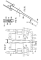
- the tool D intended to handle the assembly constituted by the centering body B, the frame 60 and the gun holder plate 64, represented in FIGS. 7 and 8, constitutes a pole made up of two coaxial tubes 80 and 82 capable of rotating. relative to each other between an engagement position and a locking position ( Figure 8).
- a plate 84 At the lower end of the outer tube 80 is fixed, for example by welding, a plate 84 provided with two vertical cylindrical guides 86 intended to cover the handling columns 73 (FIGS. 5, 8 and 9).
- a horizontal lumen is provided, over approximately three-quarters of the angular development of the guide, at the level of the horizontal groove 74 in the handling column 73.
- a blade 90 At the lower end of the inner tube 82 is fixed, for example by welding, a blade 90.
- the inner tube 82 is in the locking position (in phantom in Figure 8)
- two notches in the blade 90 come s 'Engage, through the slots 88 of the guides, in the horizontal grooves of the columns 73 and thus secure the tool D of the assembly to be manipulated.
- the blade 90 releases the handling columns 73 and makes it possible to engage the tool, then to release it, once the centering body B brought to the tip as shown in Figure 9.
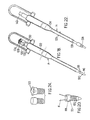
- Tool G shown in Figures 12 to 14 is intended to allow this verification from the service floor placed above the pool.
- Tool G consists of an external tube 94, the end portion of which is designed to cover one of the pins 39.
- This external tube 94 contains an internal sliding tube 96 which acts as a feeler and makes it possible to determine the difference in level. between the end of the pin and the end of the external tube resting on the part whose level is to be checked, constituted by one of the sleeves 76 (FIG. 14).
- a direct indication of the level difference is provided by a graduation engraved on the tube internal and appearing in a window 98 of the external tube 94 (FIG. 12).
- Tool G like tool 59 and most of those which will be described later, has a ring allowing the tool to be suspended from a handling crane.
- the guide tubes 15 are thus caused to be replaced correctly in the housings of the end piece during reassembly.
- the insertion and removal of the cones 106 can be carried out using the tool E shown in FIGS. 15 to 17.
- This tool comprises an external tube 108 provided at its lower part with a conical housing 109 of shape corresponding to that of the centering cones 106, constituted by rods with conical ends and with threaded middle part.
- This outer tube is joined in rotation to the cone on which it is engaged by insertion of two pins 110 in grooves 111 of the cones ( Figure 16).
- In the outer tube 108 can rotate a central rod 112, operable using a knurled button 114, the threaded end of which can be screwed into the cones.
- the two tools are intended to be used on assemblies comprising sockets 53 which, when the assembly is ready to be used, are crimped onto the end piece.
- Tool F is intended to serve the sockets and the unscrews ser, then to transfer them, and finally to replace new sockets which are later crimped using tool H.
- Tool F comprises a body, the end part of which is intended to come into engagement with a socket.
- This terminal part comprises a cone 116 for centering in the guide tube 15, then a portion having a crosspiece 118 intended to be housed in four 90 ° cells which have the crimped sockets (FIG. 24). This portion is crossed by a retractable finger 120 to retain the sockets during their transfer.
- a rotary rod 122 Figure 21
- a knurled disc 124 Figure 18
- a second disc 126 keyed sliding on the rod, is pushed by a spring 128 towards a hexagon 130 secured to the body which it makes it possible to drive in rotation.
- the disc 126 is provided with a lug 132 which cooperates with notches of the hexagon 130 so as to lock the rod in two angular positions corresponding, one to the retraction of the lug 120, the other to the projection of this lug 120 out of the lower part of the tool.
- the crimping tool H shown in FIGS. 22 and 23 is intended to push a thin wall of the cylindrical head of the new sockets (FIG. 24) into housings provided for this purpose in the upper end piece 14.
- It has for this purpose a outer tube 134, the lower part of which comprises lugs 135 intended to be housed in the bayonet grooves 54 of the centering barrels 52 (FIG. 6).
- a rod 136 In the tube 134 is mounted a rod 136 in two parts.
- the lower part of the rod carries a mandrel 138 for crimping the sockets by giving them the shape indicated on the right in FIG. 24. It is linked in rotation to the outer tube 134 in which it can slide axially over a length determined by a sliding keying (not shown).
- the upper part of the rod bears axially against the lower part. It is connected to the outer tube by a screw-nut connection which allows, by rotating it using a square 140, to exert on the lower part an axial thrust force of deformation of the sleeve. This effort can be measured by acting on the square 140 using a torque wrench.
- the installation also includes a tool J intended to intervene on the assembly once the upper end piece has been dismantled using the means described so far.
- This tool J makes it possible to extract the defective fuel rods, to evacuate them, then to replace a replacement element, constituted by a new pencil or an element having the same external shape.
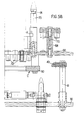
- Tool J shown in Figures 25 to 35, can be viewed as consisting of two vertical poles 142 and 144 and a centering frame, movable as a block.
- the pole 142 constitutes the main body containing the gripping device.
- the auxiliary pole 144 ( Figures 31-35) is used to move, in plan, the gripping tool relative to the frame 145 once the latter engaged in the base plate A ( Figure 35) and to bring exactly the gripper facing the location of an assembly where a pencil is to be grabbed or deposited.
- Each pole consists of a low section 146 and a high section 148.
- the two high sections on the one hand, the two low sections on the other hand, are integral so as to constitute an assembly of shorter length than that of the tool, which can be handled as a whole. The transport of the tool is thus facilitated.
- Each upper section is fixed to the corresponding lower section by removable means, such as screws for the pole 142.
- the bottom section 146 contains and guides the pencil gripper and protects the latter when it has been lifted, during the vertical and horizontal movements of the tool J.
- the top section 148 contains the assembly control members, connected to the movable members of the bottom section 146 by also removable means, which will not be described because they may have any classic constitution.
- the bottom section 146 of the pole 142 includes an outer jacket 149 which constitutes a structural member.
- a sheath 150 In this jacket 149 is placed a sheath 150, surrounded by a tube 151 intended to increase the rigidity of the section 146.
- the sheath 150 and the tube 151 remain stationary during the installation and removal of a pencil in the assembly 10
- In the sleeve 150 are concentrically disposed a composite tube 152 for closing a gripper 154 and a feeler 156. All of these elements can be connected to corresponding control members located in the section 148 by means contained in the zone- shown in external view in Figure 31.
- the lower part of the sleeve 149 is fixed to a carriage 166 for rough alignment of the sleeve 150 with the appropriate pencil location, carriage capable of moving in horizontal translation on the frame 145.
- This frame 145 (FIGS. 31-33 and 35) comprises two horizontal parallel rails 162 connected by crosspieces. It is provided with centering pins 163 (FIG. 33) intended to engage in the holes of the strips 40 of the base plate A (FIGS. 5A, 5B).
- the rails 162 have a notched circular section. They guide and imprison four rollers 164 with a vertical axis, carried. by the carriage 166 which comprises two rings 158 and 160, intended respectively to retain in axial translation the poles 142 and 144.
- One of the rails 162 is provided with a rack 168 serving for the approximate positioning of the sheath, as will be seen more far.
- the sleeve -150 (FIGS. 26-31) is of tubular shape and of sufficiently small thickness to present a slight flexibility on its free part, between an upper flange 170 for connection with the upper section 148 and a lower sleeve 172 which turns freely on the sleeve and in the ring 158, sleeve which also retains the tube 151 in translation.
- the sleeve 172 is eccentric to allow the sheath to be centered precisely, as we will see more far.
- the composite tube 152 is in several assembled parts. Its diameter is smaller at the lower part than at the top so that it can be placed vertically from the pencil 11 to be extracted without being hindered by the guide tubes 15 and by the centering cones 106 put in place during disassembly of the upper nozzle.
- the tube 152 is free to slide, inside the sleeve 150, over the length necessary for the extracted pencil to be completely protected by the sleeve 150: this length frequently exceeds 4 m in installations intended for current fuel assemblies.
- the function of the composite tube 152 is to close the gripper 154 for gripping the pencil and to transmit the force of insertion of the pencil by exerting a vertical force on a shoulder formed on the plug, as shown in FIG. 29.
- the upper part of the composite tube is provided with a flange (not visible in the figures) for connection with the corresponding element of the upper section.
- the clamp 154 (FIG. 29) is designed to be in the open position during the approach towards the pencil and to be closed by the axial displacement of the composite tube 152, after coming into contact with the feeler 156. It is constituted by elastic fingers of a part 174, generally made of stainless steel, screwed onto a tubular end-piece 176 which also guides the probe 156. This end-piece 176 is connected to the top section by sliding means (not visible in the figures).
- the purpose of the probe 156 which can be moved along the axis of the pole 142, is to verify that the head of the pencil 11 is correctly positioned relative to the clamp 154 before the latter is closed. In its rest position ( Figure 26), this probe exceeds the low level of the clamp 154 by a determined length, for example 10 mm. Its lower part consists of a small diameter stainless steel rod. It is connected to a corresponding element in the upper section 148 by a tube terminated by a threaded end (not visible in the figures).
- the lower section of the auxiliary pole 144 is retained in translation at each of its ends relative to the jacket 149 of the main body, by the ring 160 and by a collar 178 ( Figure 31). It consists of two coaxial tubes 180 and 182, free to rotate relative to each other, but retained in axial translation.
- the lower end of the inner tube 180 carries a toothing 184 which meshes with the rack 168 carried by one of the rails. It is therefore possible, by rotation of the tube 180, to move the pins 163, integral with the rails 162, relative to the lower end of the sleeve 150, therefore making an approximate adjustment.
- the outer tube 182 is intended for fine adjustment of the lower end of the sleeve 150. To this end, it carries a toothed crown 186 for driving the sleeve 172 eccentric around the axis of the clamp.
- the offset for example 2.5 mm, allows fine adjustment in plan of the position of the sleeve.
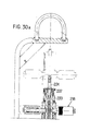
- the top section of the pole 142 (FIGS. 30 and 31) comprises an outer jacket 188 extended upwards by the sleeve 190 and which envelops the control mechanisms.
- the assembly thus formed rests, by means of springs 192, on a centering bearing 194 secured to means for hooking to the traveling crane.
- An apparatus 195 for measuring the relative displacement between the bearing 194 and the sleeve (190) (FIG. 34) indicates the traction or pressure force exerted on the rod during extraction or introduction.
- the lower part of the jacket 188 is provided with a flange 196 (FIG. 31) for connection with the end flange 170 of the jacket 149 of the bottom section.
- a plain bearing 198 fixed in the upper part of the jacket 188 guides a tube 200 fixed to the composite tube 152.
- Tubes 200 and 152 SQ -t vertically movable en bloc, using a mechanism placed in the top section of the pole 142.
- this mechanism is manually controlled. It comprises a flywheel 202 linked by a shaft to a pinion 204 driving a rack 206 secured to the tube 200.
- the assembly movable vertically can be balanced by pneumatic pressure.
- the lower part of the tube 200 constitutes a piston 208 delimiting, with the jacket 188, a compartment 210 in which a channel 212 allows gas to be brought under adjustable pressure.
- the assembly also comprises additional elements for immobilizing the tube 200 in any of its positions (not shown), which are generally completed by a ratchet device on the pinion 204 or a pinion belonging to a symmetrical assembly arranged on the other side of the tube 200 to balance the lateral forces.
- This ratchet device allows the descent of the movable assembly vertically only on intervention of an operator.
- the top section of the pole 142 also contains a tube 216 intended to transmit the locking movement of the clamp 154 and the thrust of placing a pencil 11 in the assembly 10.
- the tube 216 is immobilizable, relative to the tube 200 which carries the rack 206, by a locking device 218 with two positions (clamp open, clamp closed).
- the lower part of this tube 216 carries a connection flange with the composite tube 152.
- the weight of this assembly is balanced by a spring 220 bearing on the rack-holder assembly and on which rests a nut 222 adjustable on a threaded rod 224 fixed to the tube 216 ( Figure 32).
- the upper section 146 is provided with means for indicating the position of the feeler 156 relative to the forceps and, therefore, the position of the forceps relative to the pencil when the latter is taken.
- These means can be constituted by a graduation engraved on the tube 200 and of which a variable fraction depending on the position of the probe appears above the bearing 198.
- the upper section of the auxiliary pole 144 (FIG. 30A) consists of two rotary tubes 221 and 222 which are connected to the tubes 180 and 182 of the lower section by means of rotary drive which are released when the section 144 is raised.
- the tubes 221 and 222 are each provided at their upper end with a rotational drive mechanism constituted by a tangent wheel secured to the tube and a worm which can be actuated manually (FIG. 30). By rotation of the tubes 221 and 222, it is possible successively to make an approximate adjustment and a fine adjustment in plan of the position of the sheath.
- the sequence of repair operations for an assembly 10, by removing a defective pencil and inserting a replacement element, may be the following in the installation which has just been described.
- the assembly 10 to be repaired is first deposited, using a conventional fuel handling tool, in the repair cell 21 attached to a support installed in the pool, in the spent fuel evacuation pit (figure 2).
- the cell is then raised to the high level, indicated in phantom in Figure 2.
- the clamping means fitted to the base plate A ( Figures 4 and 5) are actuated to immobilize the assembly 10 in the cell.
- the centering body B and the frame C are brought to the upper end piece 14 using the tool D.
- the centering body is then locked to the upper end piece by engaging the claws 43 using tool 59 ( Figures 10 and 11).
- the level of the upper end piece 14 is identified using the height measuring tool G ( Figures 12-14).
- Each socket 53 for fixing the end piece to the guide tubes is removed in turn using the tool F.
- the tool F is fully inserted into the socket to be removed, lug 120 retracted.
- the spider 118 then engages in the zones provided for this purpose of the thin part of the sleeve.
- the lug 120 projects under the bushing and makes it possible to remove the latter.
- the twenty-four irradiated sockets thus extracted are deposited in rings 66 of the gun holder plate 64, already provided with twenty-four new sockets.
- the centering cones 106 are placed in the tie rods 15. It is then possible, by means of the handling tool D, to evacuate the centering body B and the end piece 14 towards the storage stand.
- the removal of the upper end piece gives access to the defective rods 11.
- the cavity 21 is firstly lowered to the position shown in solid lines in FIG. 2.
- the tool J is brought above of the cell, then lowered so as to engage the centering pins 163 equipping its frame in the appropriate holes of the strips 40 of the base plate ( Figure 35).
- the lower end of the sleeve 150 and of the clamp is then moved horizontally until it is exactly at the right of the pencil to be removed, by action on the tubes of the auxiliary pole 144.
- the clamp 154 is lowered onto the pencil ( Figure 29), its arrival in the gripping position being indicated by the probe 156.
- the clamp 154 is then closed by lowering the composite tube 152, then the clamp 154, the tube 152 and the pencil 11 are raised until that the latter is completely contained in the sheath 150 which protects it.
- the pencil is then completely disengaged from the cell and can be transported to a storage container.
- the replacement element is then brought in and inserted by a reverse process.
- the alveolus is raised in the position shown in phantom in Figure 2.
- the end piece 14 is replaced with its centering body B.
- the insertion of the end piece 14 is facilitated by the cones of centering 106 screwed in place of sockets 53.
- the position of the end piece is checked using the height measuring tool G.
- the means of tightening the first grid in the base plate A are released using the tool 59 coming from engage on the operating square 36.
- the twenty-four centering cones are unscrewed, then removed, using tool E.
- the twenty-four sockets 53 are put in place and screwed using the tool F then deformed using tool H.
- the claws of the centering body B are released from the end piece using tool 59.
- the repaired assembly can then be removed. For this, the cell 21 which contains it is lowered and the assembly 10 is resumed using the fuel handling tool carried by the bridge bridge of the swimming pool.
Landscapes
- Physics & Mathematics (AREA)
- Engineering & Computer Science (AREA)
- Plasma & Fusion (AREA)
- General Engineering & Computer Science (AREA)
- High Energy & Nuclear Physics (AREA)
- Monitoring And Testing Of Nuclear Reactors (AREA)
- Fuel Cell (AREA)
- Electrical Discharge Machining, Electrochemical Machining, And Combined Machining (AREA)
Applications Claiming Priority (2)
| Application Number | Priority Date | Filing Date | Title |
|---|---|---|---|
| FR8219162 | 1982-11-16 | ||
| FR8219162A FR2536201B1 (fr) | 1982-11-16 | 1982-11-16 | Installation de reparation d'assemblages de combustible nucleaire |
Publications (3)
| Publication Number | Publication Date |
|---|---|
| EP0109902A1 true EP0109902A1 (de) | 1984-05-30 |
| EP0109902B1 EP0109902B1 (de) | 1987-01-21 |
| EP0109902B2 EP0109902B2 (de) | 1993-11-03 |
Family
ID=9279218
Family Applications (1)
| Application Number | Title | Priority Date | Filing Date |
|---|---|---|---|
| EP83402208A Expired - Lifetime EP0109902B2 (de) | 1982-11-16 | 1983-11-16 | Vorrichtung zur Wiederherstellung von Brennstoffanordnungen |
Country Status (9)
| Country | Link |
|---|---|
| US (1) | US4659537A (de) |
| EP (1) | EP0109902B2 (de) |
| JP (1) | JPS59145996A (de) |
| KR (1) | KR910005730B1 (de) |
| DE (1) | DE3369418D1 (de) |
| ES (1) | ES8701416A1 (de) |
| FR (1) | FR2536201B1 (de) |
| YU (1) | YU225283A (de) |
| ZA (1) | ZA838515B (de) |
Cited By (14)
| Publication number | Priority date | Publication date | Assignee | Title |
|---|---|---|---|---|
| EP0183068A1 (de) * | 1984-11-13 | 1986-06-04 | Westinghouse Electric Corporation | Haltevorrichtung zum Ausbau und Austausch eines Endstücks eines wiederherstellbaren Brennstoffelements |
| EP0187651A1 (de) * | 1985-01-08 | 1986-07-16 | Westinghouse Electric Corporation | Halterung zum Einführen von Arretierungsrohren in wiederherstellbare Kernbrennelemente |
| EP0194330A1 (de) * | 1985-03-13 | 1986-09-17 | ACEC, Société Anonyme | Verfahren zum Ersetzen von Schrauben eines bestrahlten Brennstoffbündels und Anordnung zur Verwendung dieses Verfahrens |
| EP0175974A3 (en) * | 1984-09-26 | 1987-01-14 | Westinghouse Electric Corporation | Apparatus and method for removing a top nozzle in reconstituting a fuel assembly |
| US4664874A (en) * | 1985-09-05 | 1987-05-12 | Westinghouse Electric Corp. | Reusable locking tube insertion and removal fixture and method in a reconstitutable fuel assembly |
| US4688416A (en) * | 1985-11-12 | 1987-08-25 | Westinghouse Electric Corp. | Fixture and method for rectifying damaged guide thimble insert sleeves in a reconstitutable fuel assembly |
| EP0209262A3 (en) * | 1985-06-20 | 1988-04-13 | Westinghouse Electric Corporation | Nuclear fuel rod loading fixture for use in a remote repair system |
| EP0263336A3 (en) * | 1986-10-08 | 1988-10-26 | Westinghouse Electric Corporation | Improved reconstitution and repair system for nuclear fuel rod assemblies |
| FR2641117A1 (de) * | 1988-12-28 | 1990-06-29 | Framatome Sa | |
| EP0493259A1 (de) * | 1990-12-28 | 1992-07-01 | Framatome | Verfahren und Vorrichtung zur Reparatur eines Abstandhalters in einem Kernreaktorbrennstabbündel |
| EP0518497A1 (de) * | 1991-05-17 | 1992-12-16 | General Electric Company | Oberer Verschlussstopfen für Teillängenbrennstob und Greifvorrichtung dafür |
| BE1008994A3 (fr) * | 1994-07-07 | 1996-10-01 | Framatome Sa | Dispositif de pose et d'extraction d'un manchon de blocage d'un tube-guide dans un embout demontable d'un assemblage combustible de reacteur nucleaire. |
| FR2765027A1 (fr) * | 1997-06-23 | 1998-12-24 | Framatome Sa | Dispositif de reconstitution d'assemblages de combustible d'un reacteur nucleaire |
| FR3101997A1 (fr) * | 2019-10-14 | 2021-04-16 | Framatome | Dispositif de maintenance d’un assemblage de combustible, ensemble et procédé de maintenance associés |
Families Citing this family (12)
| Publication number | Priority date | Publication date | Assignee | Title |
|---|---|---|---|---|
| US4638543A (en) * | 1985-01-28 | 1987-01-27 | Westinghouse Electric Corp. | Locking tube removal fixture and method in a reconstitutable fuel assembly |
| JPH0539755Y2 (de) * | 1988-03-24 | 1993-10-08 | ||
| JP3088149B2 (ja) * | 1991-10-24 | 2000-09-18 | 三菱原子燃料株式会社 | 支持格子のスプリング操作装置 |
| DE19751688C1 (de) * | 1997-11-21 | 1999-08-19 | Siemens Ag | Adapter für einen verkürzten Brennstab eines Kernreaktor-Brennelements und Verfahren zum Einsetzen oder Herausnehmen von Brennstäben |
| US6333957B1 (en) * | 1999-11-15 | 2001-12-25 | General Electric Company | Tool kit for fabricating, inspecting and handling a nuclear fuel bundle |
| RU2249866C2 (ru) * | 2003-02-14 | 2005-04-10 | Открытое акционерное общество "Новосибирский завод химконцентратов" | Способ ремонта тепловыделяющей сборки |
| KR100958348B1 (ko) * | 2008-07-18 | 2010-05-17 | 한전원자력연료 주식회사 | 핵연료 집합체의 베인 절단장치 |
| CN102117668B (zh) * | 2009-12-31 | 2014-08-27 | 中国核动力研究设计院 | 堆芯卸料工具 |
| CN106128531B (zh) * | 2016-07-05 | 2017-10-27 | 中国核动力研究设计院 | 一种燃料组件水下管座的拆装方法 |
| FR3086790B1 (fr) * | 2018-09-27 | 2020-10-02 | Framatome Sa | Detrompeur pour embout de manutention d'element de reacteur nucleaire pour empecher la saisie par un outil de manutention d'assemblage de combustible nucleaire |
| FR3115391B1 (fr) * | 2020-10-16 | 2022-10-21 | Framatome Sa | Dispositif d’extraction d’un crayon de combustible nucléaire ou d’un crayon de grappe et procédé d’extraction utilisant un tel dispositif d’extraction |
| CN113421673B (zh) * | 2021-06-23 | 2023-02-03 | 中国核动力研究设计院 | 一种用于核反应堆控制棒加速弹簧的拆解工具 |
Citations (6)
| Publication number | Priority date | Publication date | Assignee | Title |
|---|---|---|---|---|
| FR1384145A (fr) * | 1962-12-12 | 1965-01-04 | Euratom | Dispositif de manutention et d'observation de corps allongés émettant des radiations |
| FR1570724A (de) * | 1968-04-18 | 1969-06-13 | ||
| FR2260170A1 (de) * | 1974-02-06 | 1975-08-29 | Westinghouse Electric Corp | |
| FR2298859A1 (fr) * | 1975-01-22 | 1976-08-20 | Framatome Sa | Appareil et installation d'examen des barreaux combustibles d'un reacteur nucleaire |
| FR2360963A1 (fr) * | 1976-08-06 | 1978-03-03 | Kraftwerk Union Ag | Procede de preparation d'elements combustibles partiellement consommes effectues dans le bassin a elements combustibles de reacteurs a eau sous pression |
| FR2395571A1 (fr) * | 1977-06-23 | 1979-01-19 | Framatome Sa | Dispositif de manipulation et d'examen de crayons amovibles d'assemblages combustibles |
Family Cites Families (5)
| Publication number | Priority date | Publication date | Assignee | Title |
|---|---|---|---|---|
| US3887980A (en) * | 1973-03-29 | 1975-06-10 | Exxon Nuclear Co Inc | Nuclear fuel bundle disassembly and assembly tool |
| JPS593351Y2 (ja) * | 1978-07-20 | 1984-01-30 | 三洋電機株式会社 | ヒ−トポンプ式冷暖房装置 |
| DE3002003A1 (de) * | 1980-01-21 | 1981-07-23 | Kraftwerk Union AG, 4330 Mülheim | Reparaturvorrichtung fuer brennelemente von siedewasserkernreaktoren |
| JPS5732797U (de) * | 1980-08-05 | 1982-02-20 | ||
| US4511531A (en) * | 1982-04-08 | 1985-04-16 | Westinghouse Electric Corp. | Transfer of nuclear reactor component assemblies |
-
1982
- 1982-11-16 FR FR8219162A patent/FR2536201B1/fr not_active Expired
-
1983
- 1983-11-14 ES ES527231A patent/ES8701416A1/es not_active Expired
- 1983-11-15 ZA ZA838515A patent/ZA838515B/xx unknown
- 1983-11-16 JP JP58214221A patent/JPS59145996A/ja active Pending
- 1983-11-16 YU YU02252/83A patent/YU225283A/xx unknown
- 1983-11-16 DE DE8383402208T patent/DE3369418D1/de not_active Expired
- 1983-11-16 KR KR1019830005435A patent/KR910005730B1/ko not_active Expired
- 1983-11-16 US US06/552,559 patent/US4659537A/en not_active Expired - Lifetime
- 1983-11-16 EP EP83402208A patent/EP0109902B2/de not_active Expired - Lifetime
Patent Citations (6)
| Publication number | Priority date | Publication date | Assignee | Title |
|---|---|---|---|---|
| FR1384145A (fr) * | 1962-12-12 | 1965-01-04 | Euratom | Dispositif de manutention et d'observation de corps allongés émettant des radiations |
| FR1570724A (de) * | 1968-04-18 | 1969-06-13 | ||
| FR2260170A1 (de) * | 1974-02-06 | 1975-08-29 | Westinghouse Electric Corp | |
| FR2298859A1 (fr) * | 1975-01-22 | 1976-08-20 | Framatome Sa | Appareil et installation d'examen des barreaux combustibles d'un reacteur nucleaire |
| FR2360963A1 (fr) * | 1976-08-06 | 1978-03-03 | Kraftwerk Union Ag | Procede de preparation d'elements combustibles partiellement consommes effectues dans le bassin a elements combustibles de reacteurs a eau sous pression |
| FR2395571A1 (fr) * | 1977-06-23 | 1979-01-19 | Framatome Sa | Dispositif de manipulation et d'examen de crayons amovibles d'assemblages combustibles |
Cited By (23)
| Publication number | Priority date | Publication date | Assignee | Title |
|---|---|---|---|---|
| US4667547A (en) * | 1984-09-26 | 1987-05-26 | Westinghouse Electric Corp. | Apparatus and method for removing a top nozzle in reconstituting a fuel assembly |
| EP0175974A3 (en) * | 1984-09-26 | 1987-01-14 | Westinghouse Electric Corporation | Apparatus and method for removing a top nozzle in reconstituting a fuel assembly |
| US4664875A (en) * | 1984-11-13 | 1987-05-12 | Westinghouse Electric Corp. | Top nozzle removal and replacement fixture and method in a reconstitutable fuel assembly |
| EP0183068A1 (de) * | 1984-11-13 | 1986-06-04 | Westinghouse Electric Corporation | Haltevorrichtung zum Ausbau und Austausch eines Endstücks eines wiederherstellbaren Brennstoffelements |
| EP0187651A1 (de) * | 1985-01-08 | 1986-07-16 | Westinghouse Electric Corporation | Halterung zum Einführen von Arretierungsrohren in wiederherstellbare Kernbrennelemente |
| US4638556A (en) * | 1985-01-08 | 1987-01-27 | Westinghouse Electric Corp. | Locking tube insertion fixture and method in a reconstitutable fuel assembly |
| EP0194330A1 (de) * | 1985-03-13 | 1986-09-17 | ACEC, Société Anonyme | Verfahren zum Ersetzen von Schrauben eines bestrahlten Brennstoffbündels und Anordnung zur Verwendung dieses Verfahrens |
| EP0209262A3 (en) * | 1985-06-20 | 1988-04-13 | Westinghouse Electric Corporation | Nuclear fuel rod loading fixture for use in a remote repair system |
| US4664874A (en) * | 1985-09-05 | 1987-05-12 | Westinghouse Electric Corp. | Reusable locking tube insertion and removal fixture and method in a reconstitutable fuel assembly |
| EP0223342A1 (de) * | 1985-09-05 | 1987-05-27 | Westinghouse Electric Corporation | Aufsatz zum Herausziehen und Einschieben von Sperrhülsen für wiederzusammenbaubare Kernbrennstabbündel |
| US4688416A (en) * | 1985-11-12 | 1987-08-25 | Westinghouse Electric Corp. | Fixture and method for rectifying damaged guide thimble insert sleeves in a reconstitutable fuel assembly |
| EP0263336A3 (en) * | 1986-10-08 | 1988-10-26 | Westinghouse Electric Corporation | Improved reconstitution and repair system for nuclear fuel rod assemblies |
| BE1007332A3 (fr) * | 1988-12-28 | 1995-05-23 | Framatome Sa | Dispositif et procede d'extraction de crayons peripheriques d'un assemblage combustible d'un reacteur nucleaire. |
| FR2641117A1 (de) * | 1988-12-28 | 1990-06-29 | Framatome Sa | |
| US4986955A (en) * | 1988-12-28 | 1991-01-22 | Framatome | Device for removing peripheral fuel rods from a fuel assembly of a nuclear reactor |
| EP0493259A1 (de) * | 1990-12-28 | 1992-07-01 | Framatome | Verfahren und Vorrichtung zur Reparatur eines Abstandhalters in einem Kernreaktorbrennstabbündel |
| FR2671023A1 (fr) * | 1990-12-28 | 1992-07-03 | Framatome Sa | Procede et dispositif de reparation d'une grille-entretoise d'un assemblage combustible pour reacteur nucleaire. |
| EP0518497A1 (de) * | 1991-05-17 | 1992-12-16 | General Electric Company | Oberer Verschlussstopfen für Teillängenbrennstob und Greifvorrichtung dafür |
| US5280508A (en) * | 1991-05-17 | 1994-01-18 | General Eectric Company | Partial length rod upper end plug and grapples therefor |
| BE1008994A3 (fr) * | 1994-07-07 | 1996-10-01 | Framatome Sa | Dispositif de pose et d'extraction d'un manchon de blocage d'un tube-guide dans un embout demontable d'un assemblage combustible de reacteur nucleaire. |
| FR2765027A1 (fr) * | 1997-06-23 | 1998-12-24 | Framatome Sa | Dispositif de reconstitution d'assemblages de combustible d'un reacteur nucleaire |
| FR3101997A1 (fr) * | 2019-10-14 | 2021-04-16 | Framatome | Dispositif de maintenance d’un assemblage de combustible, ensemble et procédé de maintenance associés |
| WO2021074202A1 (fr) * | 2019-10-14 | 2021-04-22 | Framatome | Dispositif de maintenance d'un assemblage de combustible, ensemble et procédé de maintenance associés |
Also Published As
| Publication number | Publication date |
|---|---|
| KR910005730B1 (ko) | 1991-08-02 |
| ES527231A0 (es) | 1986-12-01 |
| ZA838515B (en) | 1984-12-24 |
| FR2536201A1 (fr) | 1984-05-18 |
| ES8701416A1 (es) | 1986-12-01 |
| FR2536201B1 (fr) | 1985-07-19 |
| JPS59145996A (ja) | 1984-08-21 |
| YU225283A (en) | 1990-12-31 |
| EP0109902B2 (de) | 1993-11-03 |
| DE3369418D1 (en) | 1987-02-26 |
| EP0109902B1 (de) | 1987-01-21 |
| US4659537A (en) | 1987-04-21 |
| KR840006542A (ko) | 1984-11-30 |
Similar Documents
| Publication | Publication Date | Title |
|---|---|---|
| EP0109902B1 (de) | Vorrichtung zur Wiederherstellung von Brennstoffanordnungen | |
| EP0138711B1 (de) | Verfahren und Vorrichtung zur Wiederherstellung von Brennstoffanordnungen | |
| EP0317383B1 (de) | Vorrichtung zum Ausschneiden aus der Wand eines rohrförmigen Werkstückes durch Funkenerosion | |
| FR2460027A1 (fr) | Procede de manutention des assemblages et crayons combustibles lors du rechargement d'un reacteur nucleaire | |
| EP0020272B1 (de) | Beweglicher Gerätehalter für die Arbeit an einer Rohrplatte | |
| BE897468A (fr) | Procede de remplacement des broches de guidage d'un tube-guide et dispositif correspondant | |
| EP0362005A1 (de) | Verfahren und Vorrichtung zum Herausziehen von Blockierhülsen aus Führungsrohren von zerlegbaren Kernreaktor-Brennstabbündeln | |
| EP0123598B1 (de) | Drehbarer Transport- und Ersatzbehälter für verunreinigte Teile und Ergänzungsetui für diesen Behälter | |
| EP0649149B1 (de) | Anordnung zur Entnahme von Flüssigkeitsproben aus mit Schraubverschlüssen geschlossenen Behältern | |
| EP0362009B1 (de) | Vorrichtung und Verfahren zum Herausziehen von Blockierhülsen aus Führungsrohren von zerlegbaren Kernreaktorbrennstabbündeln | |
| EP0230172B1 (de) | Stabbündelgreifvorrichtung für ein Kernbrennstabbündel | |
| FR2690554A1 (fr) | Dispositif et procédé de montage de crayons dans un squelette d'assemblage combustible nucléaire. | |
| EP0344051A1 (de) | Kernbrennelementaufnahme- und Zerlegungszelle | |
| EP0360665B1 (de) | Vorrichtung zum Einsetzen von Führungsrohrblockierhülsen in ein Kopfstück eines zerlegbaren Kernreaktorbrennstabbündels | |
| EP0493259B1 (de) | Verfahren und Vorrichtung zur Reparatur eines Abstandhalters in einem Kernreaktorbrennstabbündel | |
| BE1004316A4 (fr) | Procede et installation de reconstitution d'assemblage combustible nucleaire. | |
| FR2722324A1 (fr) | Dispositif de pose et d'extraction d'un manchon de blocage d'un tube-guide dans un embout demontable d'un assemblage combustible de reacteur nucleaire | |
| WO2000038195A1 (fr) | Installation de chargement de barreaux de combustible dans un assemblage de combustible nucleaire | |
| EP0128785B1 (de) | Struktur und Gesamtheit von Mitteln zum Aufstellen von nuklearen Brennstoffelementen | |
| FR2641117A1 (de) | ||
| EP0321334A1 (de) | Apparat und Verfahren zum Abtrennen von Kernbrennstabbündelendstücken | |
| FR2517867A1 (fr) | Dispositif de fixation d'un assemblage combustible sur la plaque inferieure de support du coeur, dans un reacteur nucleaire | |
| EP0769786B1 (de) | Stange zum ferngesteuerten Eingreifen, insbesondere in einem Zerfallagerbecken eines Kernreaktors | |
| FR2600202A1 (fr) | Dispositif modulaire de compactage sous eau d'assemblages combustibles nucleaires | |
| FR2722323A1 (fr) | Procede et dispositif d'intervention sur les crayons d'un assemblage combustile pour reacteur nucleaire |
Legal Events
| Date | Code | Title | Description |
|---|---|---|---|
| PUAI | Public reference made under article 153(3) epc to a published international application that has entered the european phase |
Free format text: ORIGINAL CODE: 0009012 |
|
| AK | Designated contracting states |
Designated state(s): BE CH DE GB IT LI SE |
|
| 17P | Request for examination filed |
Effective date: 19841006 |
|
| GRAA | (expected) grant |
Free format text: ORIGINAL CODE: 0009210 |
|
| AK | Designated contracting states |
Kind code of ref document: B1 Designated state(s): BE CH DE GB IT LI SE |
|
| PG25 | Lapsed in a contracting state [announced via postgrant information from national office to epo] |
Ref country code: IT Free format text: LAPSE BECAUSE OF FAILURE TO SUBMIT A TRANSLATION OF THE DESCRIPTION OR TO PAY THE FEE WITHIN THE PRESCRIBED TIME-LIMIT;WARNING: LAPSES OF ITALIAN PATENTS WITH EFFECTIVE DATE BEFORE 2007 MAY HAVE OCCURRED AT ANY TIME BEFORE 2007. THE CORRECT EFFECTIVE DATE MAY BE DIFFERENT FROM THE ONE RECORDED. Effective date: 19870121 |
|
| REF | Corresponds to: |
Ref document number: 3369418 Country of ref document: DE Date of ref document: 19870226 |
|
| PLBI | Opposition filed |
Free format text: ORIGINAL CODE: 0009260 |
|
| 26 | Opposition filed |
Opponent name: SIEMENS AKTIENGESELLSCHAFT, BERLIN UND MUENCHEN Effective date: 19871020 |
|
| BECN | Be: change of holder's name |
Effective date: 19890511 |
|
| RAP2 | Party data changed (patent owner data changed or rights of a patent transferred) |
Owner name: FRAMATOME |
|
| REG | Reference to a national code |
Ref country code: CH Ref legal event code: PUE Owner name: FRAMATOME |
|
| PUAH | Patent maintained in amended form |
Free format text: ORIGINAL CODE: 0009272 |
|
| STAA | Information on the status of an ep patent application or granted ep patent |
Free format text: STATUS: PATENT MAINTAINED AS AMENDED |
|
| 27A | Patent maintained in amended form |
Effective date: 19931103 |
|
| AK | Designated contracting states |
Kind code of ref document: B2 Designated state(s): BE CH DE GB IT LI SE |
|
| PGFP | Annual fee paid to national office [announced via postgrant information from national office to epo] |
Ref country code: CH Payment date: 19931115 Year of fee payment: 11 |
|
| PGFP | Annual fee paid to national office [announced via postgrant information from national office to epo] |
Ref country code: SE Payment date: 19931116 Year of fee payment: 11 |
|
| PG25 | Lapsed in a contracting state [announced via postgrant information from national office to epo] |
Ref country code: SE Effective date: 19931117 |
|
| PG25 | Lapsed in a contracting state [announced via postgrant information from national office to epo] |
Ref country code: LI Effective date: 19941130 Ref country code: CH Effective date: 19941130 |
|
| EUG | Se: european patent has lapsed |
Ref document number: 83402208.9 Effective date: 19940210 |
|
| REG | Reference to a national code |
Ref country code: CH Ref legal event code: PL |
|
| APAC | Appeal dossier modified |
Free format text: ORIGINAL CODE: EPIDOS NOAPO |
|
| APAC | Appeal dossier modified |
Free format text: ORIGINAL CODE: EPIDOS NOAPO |
|
| PGFP | Annual fee paid to national office [announced via postgrant information from national office to epo] |
Ref country code: GB Payment date: 19991109 Year of fee payment: 17 |
|
| PG25 | Lapsed in a contracting state [announced via postgrant information from national office to epo] |
Ref country code: GB Free format text: LAPSE BECAUSE OF NON-PAYMENT OF DUE FEES Effective date: 20001116 |
|
| GBPC | Gb: european patent ceased through non-payment of renewal fee |
Effective date: 20001116 |
|
| PGFP | Annual fee paid to national office [announced via postgrant information from national office to epo] |
Ref country code: DE Payment date: 20011115 Year of fee payment: 19 |
|
| PGFP | Annual fee paid to national office [announced via postgrant information from national office to epo] |
Ref country code: BE Payment date: 20021212 Year of fee payment: 20 |
|
| PG25 | Lapsed in a contracting state [announced via postgrant information from national office to epo] |
Ref country code: DE Free format text: LAPSE BECAUSE OF NON-PAYMENT OF DUE FEES Effective date: 20030603 |
|
| BE20 | Be: patent expired |
Owner name: *FRAMATOME ANP Effective date: 20031116 |
|
| APAH | Appeal reference modified |
Free format text: ORIGINAL CODE: EPIDOSCREFNO |