EP0110823A2 - Pluggable connector and method of connecting it - Google Patents
Pluggable connector and method of connecting it Download PDFInfo
- Publication number
- EP0110823A2 EP0110823A2 EP83810498A EP83810498A EP0110823A2 EP 0110823 A2 EP0110823 A2 EP 0110823A2 EP 83810498 A EP83810498 A EP 83810498A EP 83810498 A EP83810498 A EP 83810498A EP 0110823 A2 EP0110823 A2 EP 0110823A2
- Authority
- EP
- European Patent Office
- Prior art keywords
- connector
- contact ring
- cable
- soldering
- inner conductor
- Prior art date
- Legal status (The legal status is an assumption and is not a legal conclusion. Google has not performed a legal analysis and makes no representation as to the accuracy of the status listed.)
- Granted
Links
Images

Classifications
-
- H—ELECTRICITY
- H01—ELECTRIC ELEMENTS
- H01R—ELECTRICALLY-CONDUCTIVE CONNECTIONS; STRUCTURAL ASSOCIATIONS OF A PLURALITY OF MUTUALLY-INSULATED ELECTRICAL CONNECTING ELEMENTS; COUPLING DEVICES; CURRENT COLLECTORS
- H01R24/00—Two-part coupling devices, or either of their cooperating parts, characterised by their overall structure
- H01R24/38—Two-part coupling devices, or either of their cooperating parts, characterised by their overall structure having concentrically or coaxially arranged contacts
- H01R24/40—Two-part coupling devices, or either of their cooperating parts, characterised by their overall structure having concentrically or coaxially arranged contacts specially adapted for high frequency
- H01R24/42—Two-part coupling devices, or either of their cooperating parts, characterised by their overall structure having concentrically or coaxially arranged contacts specially adapted for high frequency comprising impedance matching means or electrical components, e.g. filters or switches
- H01R24/44—Two-part coupling devices, or either of their cooperating parts, characterised by their overall structure having concentrically or coaxially arranged contacts specially adapted for high frequency comprising impedance matching means or electrical components, e.g. filters or switches comprising impedance matching means
-
- H—ELECTRICITY
- H01—ELECTRIC ELEMENTS
- H01R—ELECTRICALLY-CONDUCTIVE CONNECTIONS; STRUCTURAL ASSOCIATIONS OF A PLURALITY OF MUTUALLY-INSULATED ELECTRICAL CONNECTING ELEMENTS; COUPLING DEVICES; CURRENT COLLECTORS
- H01R2103/00—Two poles
-
- Y—GENERAL TAGGING OF NEW TECHNOLOGICAL DEVELOPMENTS; GENERAL TAGGING OF CROSS-SECTIONAL TECHNOLOGIES SPANNING OVER SEVERAL SECTIONS OF THE IPC; TECHNICAL SUBJECTS COVERED BY FORMER USPC CROSS-REFERENCE ART COLLECTIONS [XRACs] AND DIGESTS
- Y10—TECHNICAL SUBJECTS COVERED BY FORMER USPC
- Y10T—TECHNICAL SUBJECTS COVERED BY FORMER US CLASSIFICATION
- Y10T29/00—Metal working
- Y10T29/49—Method of mechanical manufacture
- Y10T29/49002—Electrical device making
- Y10T29/49117—Conductor or circuit manufacturing
- Y10T29/49123—Co-axial cable
-
- Y—GENERAL TAGGING OF NEW TECHNOLOGICAL DEVELOPMENTS; GENERAL TAGGING OF CROSS-SECTIONAL TECHNOLOGIES SPANNING OVER SEVERAL SECTIONS OF THE IPC; TECHNICAL SUBJECTS COVERED BY FORMER USPC CROSS-REFERENCE ART COLLECTIONS [XRACs] AND DIGESTS
- Y10—TECHNICAL SUBJECTS COVERED BY FORMER USPC
- Y10T—TECHNICAL SUBJECTS COVERED BY FORMER US CLASSIFICATION
- Y10T29/00—Metal working
- Y10T29/49—Method of mechanical manufacture
- Y10T29/49002—Electrical device making
- Y10T29/49117—Conductor or circuit manufacturing
- Y10T29/49174—Assembling terminal to elongated conductor
- Y10T29/49179—Assembling terminal to elongated conductor by metal fusion bonding
Definitions
- the present invention relates to a connector according to the preamble of independent claim 1 and a method for connecting the same according to the preamble of independent claim 6.
- the shielding reduces the radiation to a minimum.
- the electrical values must also be guaranteed in the bend.
- this is achieved in that a silver-plated copper foil has been overlapped on the dielectric layer and this first shield has been covered with a second shield made of braided silver-plated copper wire.
- the cable constructed in this way is provided with a plastic outer jacket.
- the coaxial cable 15 viewed from the inside to the outside, consists of an inner conductor 20, a layer 21 of dielectric material, for example polytetrafluoroethylene, concentrically surrounding this inner conductor, a first shield 22 made of silver-plated copper tape, which overlaps the layer 21 is, a second shield 23 made of a copper wire mesh and an outside jacket 24, for example also made of polytetrafluoroethylene.
- dielectric material for example polytetrafluoroethylene
- the coaxial connector 14 consists of the following individual parts: a nipple 1 with an external thread 1 a, which rests closely on the outer jacket 24, a contact ring 2 with a radial bore 13, which can be designed as a through bore, and a connector housing 3 with an internal thread which is complementary to the external thread 1 a 3a and with a sleeve 3b at the end opposite the internal thread 3a, a plug dielectric 5 located in the sleeve 3b, and from a union nut 8.
- a plug pin 4 with a tapered portion 11 has an axial cavity 12 for the inner conductor 20 of the inner end of the plug Coaxial cable 15 on.
- the sleeve 3b and the plug dielectric 5 are also pierced diametrically. In the assembled state, this bore 10 is aligned with the tapered part 11 of the plug pin 4. This bore 10 is cast with epoxy resin, so that a radial centering support 9 is formed.
- a snap ring 6 is inserted, which engages in a circumferential groove 8a in the inner wall of the union nut 8 and thus holds the union nut 8 freely rotatable with at most a limited axial play.
- a seal 7 made of elastic material, such as rubber, is placed on a shoulder 3c on the outside of the sleeve 3b.
- the inner conductor 20 of the coaxial cable 15 is soldered into the cavity 12 of the plug pin 4.
- the contact ring 2 rests on the second shield 3 and is also soldered to it.
- the holes 13 serve on the one hand to visually check the correct soldering, i.e. whether the soldering material has flowed correctly, and on the other hand steam and the gas of the flux can withdraw through these holes 13, so that the soldering material also has enough space to spread out.
- the coaxial cable 15 is first cut to the exact length.
- the cutting surface 24a must be flat.
- the outer jacket 24 is cut in three places 31, 32, 33 all around. This creates an outer jacket section 36, a middle jacket section 35 and an inner jacket section 34 (FIG. 3).
- the middle jacket section 35 is removed (FIG. 4) and the exposed braid of the second shield 23 is tinned.
- a melting solder at 180 0 is used, arises so that a tin-plated portion 37th
- the outer jacket section 36 is removed and a shrink tube is pushed over the cable 15 prepared in this way (this is not shown).
- Nipple 1 is now plugged from connector 14 onto outer jacket 24 (FIG. 5).
- the contact ring 2 pushed onto the tinned section 37 before the inner jacket section 34 is now removed and the contact ring 2 can be pushed up to the outer jacket 24.
- the structure according to FIG. 6 is thus obtained.
- the contact ring 2 is soldered to the shield 23.
- a soft solder melting at 180 ° is also used here.
- the cable 15 is cut off about 1.8 mm in front of the contact ring 2 (FIG. 7), and then the cut surface is turned so that the contact ring 2 is shortened by 0.1-0.2 mm.
- This procedure exposes the inner conductor 20 (FIG. 8) and the cable length can thus also be matched. This was previously not possible in such a simple manner with the known connectors.
- the plug pin 4 is now soldered onto the inner conductor 20. This can advantageously be done by means of resistance soldering.
- the cable is then inserted into the connector housing 3, and this is screwed to the nipple 1 (Fig. 10). In this state, the cable and its connection points can now be checked with the connector. If a shrink tube was pushed onto the cable in the phase according to FIG. 5, it can now be positioned correctly before it is shrunk with hot air at about 150 ° C.
- the connector shown here can also be used for an angled connection, as described, for example, in DE-A 29 09 577. 3 to 10, the cable sheath is cut through with two cuts arranged at a distance from one another. The distance of the cuts should at least approximate the bend. Then the cable is bent with the smallest possible bending radius, the cable sheath is removed and at least the outer shield is tinned. This tinning is advantageously also carried out with solder that flows at 180 ° C. The resulting sheet can be covered with a shrink molding. In this way, an angled connection can be formed in a simple and cost-effective manner, in which the cable length can be adjusted and in which the electrical conditions are constant and manageable up to the connector transition into the connection element.
Abstract
Für ein flexibles Koaxialkabel muss ein besonderer Steckverbinder geschaffen werden, mit dem an der Verbindungsstelle zum Kabel eine vergleichbare Zugfestigkeit wie die des Kabels erreicht wird. Dieser Steckverbinder (14) besteht aus einem Nippel (1), der mit einer Steckerhülse (3) verschraubt ist. Zwischen diesen beiden Steckerelementen befindet sich ein mit der Abschirmung (23) verlöteter Kontaktring (2). Dieser weist eine Bohrung (13) auf, durch die die Lötung von Auge kontrolliert werden kann und beim Löten Dämpfe abziehen können. Die Endfläche von Kontaktring (2) und Kabeldielektrikum (21) werden plangedreht. Dabei kann auch die Kabellänge genauestens abgestimmt werden. Der freigelegte Innenleiter (20) ist mit einem Steckerstift (4) verlötet. Im Steckergehäuse (3) sind Steckerdielektrikum (5), Steckerstift (4) und das Steckergehäuse (3) selbst mittels einer mit Epoxyharz (9) gefüllten Bohrung (10) bzw. Verjüngung (11) am Steckerstift (4) in starrer Lage gehaltert. Dieser Steckverbinder (14) erlaubt zudem eine genaue Kontrolle der Impedanzanpassung während und nach dem Löten.For a flexible coaxial cable, a special connector must be created with which a tensile strength comparable to that of the cable is achieved at the connection point to the cable. This connector (14) consists of a nipple (1) which is screwed to a connector sleeve (3). Between these two plug elements there is a contact ring (2) soldered to the shield (23). This has a hole (13) through which the soldering can be checked by the eye and vapors can be drawn off during soldering. The end face of the contact ring (2) and the cable dielectric (21) are face-turned. The cable length can also be fine-tuned. The exposed inner conductor (20) is soldered to a connector pin (4). The plug dielectric (5), plug pin (4) and the plug housing (3) themselves are held in a rigid position in the plug housing (3) by means of a bore (10) or taper (11) filled with epoxy resin (9) on the plug pin (4). This connector (14) also allows precise control of the impedance matching during and after soldering.
Description
Die vorliegende Erfindung betrifft einen Steckverbinder gemäss dem Oberbegriff des unabhängigen Patentanspruchs 1 sowie ein Verfahren zum Anschliessen desselben gemäss dem Oberbegriff des unabhängigen Patentanspruchs 6.The present invention relates to a connector according to the preamble of
Im "Mikrowellen Magazin" Nr. 3, 1977, vergleicht die Firma GORE & Co. GmbH, D-8011 Putzbrunn bei München, ein flexibles Koaxialkabel mit einem Semi-Rigid-Kabel. Im Aufbau zeigt ein solches flexibles Koaxialkabel einen Innenleiter aus 19-fach verlitztem, versilbertem Kupfer. Die Verlitzung ergibt die geforderte Flexibilität und verhindert ein Wandern des Innenleiters innerhalb der dielektrischen Schicht beim Biegen. Als Dielektrikum wir ein Polytetrafluoräthylen vorgeschlagen, das gestreckt wurde und damit bei einer matrizenähnlichen Struktur einen hohen Luftanteil aufweist. Zur Erzielung des notwendigen konzentrischen Aufbaus wird hier das dielektrische Material um den Innenleiter gewickelt.In "Microwave Magazine" No. 3, 1977, the company GORE & Co. GmbH, D-8011 Putzbrunn near Munich, compares a flexible coaxial cable with a semi-rigid cable. In construction, such a flexible coaxial cable shows an inner conductor made of 19-fold stranded, silver-plated copper. The stranding provides the required flexibility and prevents the inner conductor from migrating within the dielectric layer during bending. As a dielectric we propose a polytetrafluoroethylene that has been stretched and thus has a high proportion of air with a matrix-like structure. To achieve the the necessary concentric structure, the dielectric material is wrapped around the inner conductor.
Durch die Abschirmung wird bekanntlich die Abstrahlung auf ein Minimum reduziert. Bei flexiblen Koaxialkabeln müssen die elektrischen Werte auch in der Biegung gewährleistet sein. Bei dem beschriebenen Koaxialkabel wird dies dadurch erreicht, dass auf die dielektrische Schicht eine versilberte Kupferfolie überlappt gewickelt wurde und diese erste Abschirmung mit einer zweiten Abschirmung aus geflochtenem versilbertem Kupferdraht umfasst wurde. Zum Schluss wird das derart aufgebaute Kabel mit einem Kunststoff-Aussenmantel versehen.As is known, the shielding reduces the radiation to a minimum. With flexible coaxial cables, the electrical values must also be guaranteed in the bend. In the coaxial cable described, this is achieved in that a silver-plated copper foil has been overlapped on the dielectric layer and this first shield has been covered with a second shield made of braided silver-plated copper wire. Finally, the cable constructed in this way is provided with a plastic outer jacket.
In einer zweiten Veröffentlichung in derselben Zeitschrift "Mikrowellen Magazin" Nr. 4, 1980, wird darauf hingewiesen, dass eine neue Kabelkonstruktion neue Steckverbinder bedeutet. In keiner der beiden Veröffentlichungen ist ein solcher neuer Stecker mit über blosse Andeutungen hinausgehenden Merkmalen beschrieben.In a second publication in the same journal "Microwave Magazine" No. 4, 1980, it is pointed out that a new cable construction means new connectors. Neither of the two publications describes such a new plug with features that go beyond mere hints.
Es ist deshalb eine Aufgabe der Erfindung, einen Steckverbinder zu schaffen, der die besonderen Anforderungen von flexiblen Mikrowellen-Koaxialkabeln erfüllt.It is therefore an object of the invention to provide a connector that meets the special requirements of flexible microwave coaxial cables.
Erfindungsgemäss wird dies durch einen Steckverbinder mit den Merkmalen im kennzeichnenden Teil des unabhängigen Patentanspruchs 1 erreicht. Ein Verfahren zum Anschliessen des Steckverbinders ist im unabhängigen Patentanspruch 6 gekennzeichnet.According to the invention, this is achieved by a connector with the Features achieved in the characterizing part of
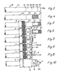
Ein Ausführungsbeispiel des erfindungsgemässen Steckverbinders wird nachfolgend anhand der Zeichnung erläutert. Es zeigen:
- Fig. 1 eine Schnittansicht eines erfindungsgemässen Steckverbinders,
- Fig. 2 dieselbe Schnittansicht wie Fig. 1 jedoch mit ebenfalls geschnitten dargestelltem Koaxialkabel,
- Fig. 3 - 10 Ansichten eines Koaxialkabels mit verschiedenen Montagestufen des Steckverbinders gemäss Fig. 1 und 2.
- 1 is a sectional view of a connector according to the invention,
- 2 shows the same sectional view as FIG. 1 but with the coaxial cable also shown in section,
- 3 - 10 views of a coaxial cable with different assembly stages of the connector according to FIGS. 1 and 2.
Das Koaxialkabel 15 gemäss Fig. 2 besteht, von innen nach aussen betrachtet, aus einem Innenleiter 20, einer diesen Innenleiter konzentrisch umfassenden Schicht 21 aus dielektrischem Material, beispielsweise Polytetrafluoräthylen, einer ersten Abschirmung 22 aus versilbertem Kupferband, das sich überlappend auf die Schicht 21 gewickelt ist, einer zweiten Abschirmung 23 aus einem Kupferdrahtgeflecht und einem Aussenmantel 24, beispielsweise auch aus Polytetrafluoräthylen.The
Der Koaxial-Steckverbinder 14 besteht aus folgenden Einzelteilen: Einem auf dem Aussenmantel 24 eng anliegenden Nippel 1 mit einem Aussengewinde la, einem Kontaktring 2 mit einer radialen Bohrung 13, die als Durchgangsbohrung ausgeführt sein kann, einem Steckergehäuse 3 mit einem zum Aussengewinde la komplementären Innengewinde 3a und mit einer Hülse 3b an dem dem Innengewinde 3a gegenüberliegenden Ende, einem in der Hülse 3b befindlichen Steckerdielektrikum 5, sowie aus einer Ueberwurfmutter 8. Ein Steckerstift 4 mit einer verjüngten Partie 11 weist am steckerinneren Ende einen axialen Hohlraum 12 für den Innenleiter 20 des Koaxialkabels 15 auf. Die Hülse 3b und das Steckerdielektrikum 5 sind ebenfalls diametral durchbohrt. Diese Bohrung 10 fluchtet im zusammengebauten Zustand mit der verjüngten Partie 11 des Steckerstiftes 4. Diese Bohrung 10 ist mit Epoxyharz vergossen, so dass eine radiale Zentrierstütze 9 gebildet ist.The
In einer umlaufenden Nut 6a in der Aussenwand der Hülse 3b ist ein Sprengring 6 eingesetzt, der in eine umlaufende Nut 8a in der Innenwand der Ueberwurfmutter 8 eingreift und damit die Ueberwurfmutter 8 frei drehbar mit höchstens einem beschränkten axialen Spiel haltert. Schliesslich ist noch eine Dichtung 7 aus elastischem Material, wie Gummi, auf eine Schulter 3c auf der Aussenseite der Hülse 3b aufgelegt.In a circumferential groove 6a in the outer wall of the
Im zusammengebauten Zustand gemäss Fig. 2 ist der Innenleiter 20 des Koaxialkabels 15 im Hohlraum 12 des Steckerstiftes 4 eingelötet. Der Kontaktring 2 liegt auf der zweiten Abschirmung 3 auf und ist mit dieser ebenfalls verlötet. Die Bohrungen 13 dienen einerseits zur optischen Kontrolle der richtigen Lötung, d.h., ob das Lötmaterial richtig geflossen ist, und anderseits kann Dampf und das Gas des Flussmittels durch diese Bohrungen 13 abziehen, so dass das Lötmaterial auch genügend Platz hat, um sich auszubreiten.In the assembled state according to FIG. 2, the
Zum Anschliessen des Steckverbinders 14 an ein Koaxialkabel 15 wird das Koaxialkabel 15 zuerst auf die genaue Länge abgeschnitten. Die Schnittfläche 24a muss plan sein. Dann wird der Aussenmantel 24 an drei Stellen 31, 32, 33 rundherum eingeschnitten. Damit entstehen ein äusserer Mantelabschnitt 36, ein mittlerer Mantelabschnitt 35 und ein innerer Mantelabschnitt 34 (Fig. 3). Als nächstes wird der mittlere Mantelabschnitt 35 entfernt (Fig. 4) und das zutagetretende Geflecht der zweiten Abschirmung 23 wird verzinnt. Dazu wird ein bei 1800 schmelzendes Weichlot verwendet, so dass eine verzinnte Partie 37 entsteht. Nun wird der äussere Mantelabschnitt 36 entfernt, und über das derart vorbereitete Kabel 15 wird ein Schrumpfschlauch geschoben (dieser ist nicht dargestellt). Vom Steckverbinder 14 wird nun der Nippel 1 auf den Aussenmantel 24 gesteckt (Fig. 5). Anschliessend wird der Kontaktring 2 auf die verzinnte Partie 37 geschoben, bevor nun der innere Mantelabschnitt 34 entfernt wird und der Kontaktring 2 bis zum Aussenmantel 24 hingeschoben werden kann. Damit wird der Aufbau gemäss Fig. 6 erhalten. In dieser Phase des Zusammenbaus wird der Kontaktring 2 mit der Abschirmung 23 verlötet. Auch hier wird ein bei 180° schmelzendes Weichlot verwendet. Nun wird das Kabel 15 etwa 1,8 mm vor dem Kontaktring 2 abgeschnitten (Fig. 7), und dann wird die Schnittfläche plangedreht, so dass der Kontaktring 2 um 0,1 - 0,2 mm gekürzt wird. Durch dieses Vorgehen wird der Innenleiter 20 freigelegt (Fig. 8) und damit kann auch die Kabellänge noch abgestimmt werden. Dies war bisher bei den bekannten Steckverbindern nicht in einer derart einfachen Weise möglich. Gemäss Fig. 9 wird nun der Steckerstift 4 auf den Innenleiter 20 gelötet. Dies kann vorteilhafterweise mittels Widerstandlöten geschehen.To connect the
Das Kabel wird daraufhin in das Steckergehäuse 3 eingeführt, und dieses wird mit dem Nippel 1 verschraubt (Fig. 10). In diesem Zustand kann nun das Kabel und dessen Verbindungsstellen mit dem Steckverbinder überprüft werden. Wenn ein Schrumpfschlauch in der Phase gemäss Fig. 5 auf das Kabel geschoben wurde, kann dieser nun richtig positioniert werden bevor er mit Heissluft bei etwa 150° C geschrumpft wird.The cable is then inserted into the
Schliesslich muss noch die Borhung 10 mit Epoxyharz vergossen und das Harz aushärten gelassen werden bevor dann noch der Sprengring 6 eingesetzt, die Dichtung 7 und schlussendlich die Ueberwurfmutter 8 aufgesetzt werden kann. Für einen abgewinkelten Anschluss, wie er beispielsweise in der DE-A 29 09 577 beschrieben ist, lässt sich der hier dargestellte Steckverbinder ebenfalls verwenden. An dem mit dem Steckverbinder durch die Verfahrensschritte gemäss Fig. 3 bis 10 fertiggestellte Kabel wird mit zwei im Abstand voneinander angeordneten Schnitte der Kabelmantel durchtrennt. Der Abstand der Schnitte soll wenigstens angenähert die Biegung einschliessen. Dann wird das Kabel mit dem kleinst möglichen Biegeradius gebogen, der Kabelmantel entfernt und wenigstens die äussere Abschirmung verzinnt. Diese Verzinnung wird vorteilhafterweise auch mit Lötzinn vorgenommen, das bei 180 C fliesst. Der entstandene Bogen kann zum Schluss noch mittels eines Schrumpfformteils abgedeckt werden. Damit kann auf einfache und kostengünstige Weise ein Winkelanschluss gebildet werden, bei dem die Kabellänge abgeglichen werden kann und bei dem die elektrischen Verhältnisse bis zum Stecker- übergang in das Anschlusselement gleichbleibend und beherrschbar sind.Finally, the borehole 10 has to be cast with epoxy resin and the resin is allowed to harden before the
Claims (9)
Applications Claiming Priority (2)
| Application Number | Priority Date | Filing Date | Title |
|---|---|---|---|
| CH685782 | 1982-11-24 | ||
| CH6857/82 | 1982-11-24 |
Publications (3)
| Publication Number | Publication Date |
|---|---|
| EP0110823A2 true EP0110823A2 (en) | 1984-06-13 |
| EP0110823A3 EP0110823A3 (en) | 1987-02-04 |
| EP0110823B1 EP0110823B1 (en) | 1988-06-15 |
Family
ID=4316120
Family Applications (1)
| Application Number | Title | Priority Date | Filing Date |
|---|---|---|---|
| EP83810498A Expired EP0110823B1 (en) | 1982-11-24 | 1983-10-31 | Pluggable connector and method of connecting it |
Country Status (3)
| Country | Link |
|---|---|
| US (2) | US4545637A (en) |
| EP (1) | EP0110823B1 (en) |
| DE (1) | DE3377097D1 (en) |
Cited By (2)
| Publication number | Priority date | Publication date | Assignee | Title |
|---|---|---|---|---|
| FR2591040A1 (en) * | 1985-11-29 | 1987-06-05 | Radiall Ind | HERMETIC COAXIAL CONNECTOR |
| FR2734970A1 (en) * | 1995-06-01 | 1996-12-06 | Huber+Suhner Ag | COAXIAL ELECTRICAL LINK LINE |
Families Citing this family (112)
| Publication number | Priority date | Publication date | Assignee | Title |
|---|---|---|---|---|
| US4666230A (en) * | 1984-12-27 | 1987-05-19 | Microwave Systems & Technology, Inc. | Coaxial cable connector assembly |
| US4690482A (en) * | 1986-07-07 | 1987-09-01 | The United States Of America As Represented By The Secretary Of The Navy | High frequency, hermetic, coaxial connector for flexible cable |
| US4917631A (en) * | 1988-12-02 | 1990-04-17 | Uti Corporation | Microwave connector |
| US5060373A (en) * | 1989-08-22 | 1991-10-29 | The Phoenix Company Of Chicago, Inc. | Methods for making coaxial connectors |
| JPH0810933Y2 (en) * | 1990-01-16 | 1996-03-29 | 日本電気株式会社 | Coaxial connector |
| ATE127894T1 (en) * | 1990-01-18 | 1995-09-15 | Oneil Alexander G B | FLUID CONNECTOR. |
| DE4206092C1 (en) * | 1992-02-27 | 1993-07-01 | Spinner Gmbh Elektrotechnische Fabrik, 8000 Muenchen, De | |
| US5161993A (en) * | 1992-03-03 | 1992-11-10 | Amp Incorporated | Retention sleeve for coupling nut for coaxial cable connector and method for applying same |
| US5269701A (en) * | 1992-03-03 | 1993-12-14 | The Whitaker Corporation | Method for applying a retention sleeve to a coaxial cable connector |
| US5281167A (en) * | 1993-05-28 | 1994-01-25 | The Whitaker Corporation | Coaxial connector for soldering to semirigid cable |
| US5470257A (en) * | 1994-09-12 | 1995-11-28 | John Mezzalingua Assoc. Inc. | Radial compression type coaxial cable end connector |
| US6273736B1 (en) * | 1997-07-22 | 2001-08-14 | Applied Materials, Inc. | Safety guard for an RF connector |
| US6153830A (en) | 1997-08-02 | 2000-11-28 | John Mezzalingua Associates, Inc. | Connector and method of operation |
| USD440939S1 (en) | 1997-08-02 | 2001-04-24 | Noah P. Montena | Open compression-type coaxial cable connector |
| US6605783B1 (en) * | 1997-10-14 | 2003-08-12 | Fitel Usa Corp. | Non-metallic transmission cables and method for terminating the same |
| USD436076S1 (en) | 2000-04-28 | 2001-01-09 | John Mezzalingua Associates, Inc. | Open compression-type coaxial cable connector |
| USD437826S1 (en) | 2000-04-28 | 2001-02-20 | John Mezzalingua Associates, Inc. | Closed compression-type coaxial cable connector |
| MXPA02000336A (en) | 2000-05-10 | 2002-06-21 | Thomas & Betts Int | Coaxial connector having detachable locking sleeve. |
| US6786767B1 (en) * | 2000-06-27 | 2004-09-07 | Astrolab, Inc. | Connector for coaxial cable |
| USD461778S1 (en) | 2001-09-28 | 2002-08-20 | John Mezzalingua Associates, Inc. | Co-axial cable connector |
| USD462327S1 (en) | 2001-09-28 | 2002-09-03 | John Mezzalingua Associates, Inc. | Co-axial cable connector |
| USD468696S1 (en) | 2001-09-28 | 2003-01-14 | John Mezzalingua Associates, Inc. | Co-axial cable connector |
| USD462058S1 (en) | 2001-09-28 | 2002-08-27 | John Mezzalingua Associates, Inc. | Co-axial cable connector |
| USD461166S1 (en) | 2001-09-28 | 2002-08-06 | John Mezzalingua Associates, Inc. | Co-axial cable connector |
| USD458904S1 (en) | 2001-10-10 | 2002-06-18 | John Mezzalingua Associates, Inc. | Co-axial cable connector |
| USD475975S1 (en) | 2001-10-17 | 2003-06-17 | John Mezzalingua Associates, Inc. | Co-axial cable connector |
| US6667440B2 (en) | 2002-03-06 | 2003-12-23 | Commscope Properties, Llc | Coaxial cable jumper assembly including plated outer conductor and associated methods |
| US6929507B2 (en) * | 2003-12-30 | 2005-08-16 | Huang Liang Precision Enterprise Co., Ltd. | Coaxial connector structure |
| US7329149B2 (en) | 2004-01-26 | 2008-02-12 | John Mezzalingua Associates, Inc. | Clamping and sealing mechanism with multiple rings for cable connector |
| US6808415B1 (en) | 2004-01-26 | 2004-10-26 | John Mezzalingua Associates, Inc. | Clamping and sealing mechanism with multiple rings for cable connector |
| US7029304B2 (en) * | 2004-02-04 | 2006-04-18 | John Mezzalingua Associates, Inc. | Compression connector with integral coupler |
| US7241172B2 (en) | 2004-04-16 | 2007-07-10 | Thomas & Betts International Inc. | Coaxial cable connector |
| US7063565B2 (en) | 2004-05-14 | 2006-06-20 | Thomas & Betts International, Inc. | Coaxial cable connector |
| DE102004031271B4 (en) * | 2004-06-28 | 2008-02-14 | Ims Connector Systems Gmbh | RF connector for coaxial cable |
| US8157589B2 (en) | 2004-11-24 | 2012-04-17 | John Mezzalingua Associates, Inc. | Connector having a conductively coated member and method of use thereof |
| US20060110977A1 (en) | 2004-11-24 | 2006-05-25 | Roger Matthews | Connector having conductive member and method of use thereof |
| US7114990B2 (en) * | 2005-01-25 | 2006-10-03 | Corning Gilbert Incorporated | Coaxial cable connector with grounding member |
| IL174146A0 (en) | 2005-03-11 | 2006-08-01 | Thomas & Betts Int | Coaxial connector with a cable gripping feature |
| CN101253656B (en) | 2005-06-27 | 2012-01-11 | 普罗布兰德国际有限公司 | End connector for coaxial cable |
| US7455549B2 (en) | 2005-08-23 | 2008-11-25 | Thomas & Betts International, Inc. | Coaxial cable connector with friction-fit sleeve |
| US7288002B2 (en) | 2005-10-19 | 2007-10-30 | Thomas & Betts International, Inc. | Coaxial cable connector with self-gripping and self-sealing features |
| US7347729B2 (en) | 2005-10-20 | 2008-03-25 | Thomas & Betts International, Inc. | Prepless coaxial cable connector |
| US7517235B2 (en) | 2006-12-28 | 2009-04-14 | General Electric Company | Press fit connection for mounting electrical plug-in outlet insulator to a busway aluminum housing |
| US7588460B2 (en) | 2007-04-17 | 2009-09-15 | Thomas & Betts International, Inc. | Coaxial cable connector with gripping ferrule |
| US7794275B2 (en) | 2007-05-01 | 2010-09-14 | Thomas & Betts International, Inc. | Coaxial cable connector with inner sleeve ring |
| US7566236B2 (en) | 2007-06-14 | 2009-07-28 | Thomas & Betts International, Inc. | Constant force coaxial cable connector |
| US7628646B1 (en) * | 2008-07-01 | 2009-12-08 | Cablesat International Co., Ltd. | Cable connector and method of assembling cable connector and cable |
| US8075337B2 (en) | 2008-09-30 | 2011-12-13 | Belden Inc. | Cable connector |
| US8025518B2 (en) | 2009-02-24 | 2011-09-27 | Corning Gilbert Inc. | Coaxial connector with dual-grip nut |
| US8029315B2 (en) | 2009-04-01 | 2011-10-04 | John Mezzalingua Associates, Inc. | Coaxial cable connector with improved physical and RF sealing |
| US7824216B2 (en) | 2009-04-02 | 2010-11-02 | John Mezzalingua Associates, Inc. | Coaxial cable continuity connector |
| US7892005B2 (en) | 2009-05-19 | 2011-02-22 | John Mezzalingua Associates, Inc. | Click-tight coaxial cable continuity connector |
| US9017101B2 (en) | 2011-03-30 | 2015-04-28 | Ppc Broadband, Inc. | Continuity maintaining biasing member |
| US8573996B2 (en) | 2009-05-22 | 2013-11-05 | Ppc Broadband, Inc. | Coaxial cable connector having electrical continuity member |
| US8444445B2 (en) | 2009-05-22 | 2013-05-21 | Ppc Broadband, Inc. | Coaxial cable connector having electrical continuity member |
| US9570845B2 (en) | 2009-05-22 | 2017-02-14 | Ppc Broadband, Inc. | Connector having a continuity member operable in a radial direction |
| US8287320B2 (en) | 2009-05-22 | 2012-10-16 | John Mezzalingua Associates, Inc. | Coaxial cable connector having electrical continuity member |
| US8272893B2 (en) | 2009-11-16 | 2012-09-25 | Corning Gilbert Inc. | Integrally conductive and shielded coaxial cable connector |
| US7934954B1 (en) | 2010-04-02 | 2011-05-03 | John Mezzalingua Associates, Inc. | Coaxial cable compression connectors |
| US9166306B2 (en) | 2010-04-02 | 2015-10-20 | John Mezzalingua Associates, LLC | Method of terminating a coaxial cable |
| US8468688B2 (en) | 2010-04-02 | 2013-06-25 | John Mezzalingua Associates, LLC | Coaxial cable preparation tools |
| US8177582B2 (en) | 2010-04-02 | 2012-05-15 | John Mezzalingua Associates, Inc. | Impedance management in coaxial cable terminations |
| TWI549386B (en) | 2010-04-13 | 2016-09-11 | 康寧吉伯特公司 | Coaxial connector with inhibited ingress and improved grounding |
| US8152551B2 (en) | 2010-07-22 | 2012-04-10 | John Mezzalingua Associates, Inc. | Port seizing cable connector nut and assembly |
| US8079860B1 (en) | 2010-07-22 | 2011-12-20 | John Mezzalingua Associates, Inc. | Cable connector having threaded locking collet and nut |
| US8113879B1 (en) | 2010-07-27 | 2012-02-14 | John Mezzalingua Associates, Inc. | One-piece compression connector body for coaxial cable connector |
| US8888526B2 (en) | 2010-08-10 | 2014-11-18 | Corning Gilbert, Inc. | Coaxial cable connector with radio frequency interference and grounding shield |
| US8556656B2 (en) | 2010-10-01 | 2013-10-15 | Belden, Inc. | Cable connector with sliding ring compression |
| US8167636B1 (en) | 2010-10-15 | 2012-05-01 | John Mezzalingua Associates, Inc. | Connector having a continuity member |
| US8167635B1 (en) | 2010-10-18 | 2012-05-01 | John Mezzalingua Associates, Inc. | Dielectric sealing member and method of use thereof |
| US8167646B1 (en) | 2010-10-18 | 2012-05-01 | John Mezzalingua Associates, Inc. | Connector having electrical continuity about an inner dielectric and method of use thereof |
| US8075338B1 (en) | 2010-10-18 | 2011-12-13 | John Mezzalingua Associates, Inc. | Connector having a constant contact post |
| US8323053B2 (en) | 2010-10-18 | 2012-12-04 | John Mezzalingua Associates, Inc. | Connector having a constant contact nut |
| TWI558022B (en) | 2010-10-27 | 2016-11-11 | 康寧吉伯特公司 | Push-on cable connector with a coupler and retention and release mechanism |
| US8337229B2 (en) | 2010-11-11 | 2012-12-25 | John Mezzalingua Associates, Inc. | Connector having a nut-body continuity element and method of use thereof |
| US8414322B2 (en) | 2010-12-14 | 2013-04-09 | Ppc Broadband, Inc. | Push-on CATV port terminator |
| US8398421B2 (en) | 2011-02-01 | 2013-03-19 | John Mezzalingua Associates, Inc. | Connector having a dielectric seal and method of use thereof |
| US8157588B1 (en) | 2011-02-08 | 2012-04-17 | Belden Inc. | Cable connector with biasing element |
| US8465322B2 (en) | 2011-03-25 | 2013-06-18 | Ppc Broadband, Inc. | Coaxial cable connector |
| US8342879B2 (en) | 2011-03-25 | 2013-01-01 | John Mezzalingua Associates, Inc. | Coaxial cable connector |
| US8366481B2 (en) | 2011-03-30 | 2013-02-05 | John Mezzalingua Associates, Inc. | Continuity maintaining biasing member |
| US8388377B2 (en) | 2011-04-01 | 2013-03-05 | John Mezzalingua Associates, Inc. | Slide actuated coaxial cable connector |
| US8348697B2 (en) | 2011-04-22 | 2013-01-08 | John Mezzalingua Associates, Inc. | Coaxial cable connector having slotted post member |
| WO2012162431A2 (en) | 2011-05-26 | 2012-11-29 | Belden Inc. | Coaxial cable connector with conductive seal |
| US9711917B2 (en) | 2011-05-26 | 2017-07-18 | Ppc Broadband, Inc. | Band spring continuity member for coaxial cable connector |
| US8758050B2 (en) | 2011-06-10 | 2014-06-24 | Hiscock & Barclay LLP | Connector having a coupling member for locking onto a port and maintaining electrical continuity |
| US8591244B2 (en) | 2011-07-08 | 2013-11-26 | Ppc Broadband, Inc. | Cable connector |
| US9190744B2 (en) | 2011-09-14 | 2015-11-17 | Corning Optical Communications Rf Llc | Coaxial cable connector with radio frequency interference and grounding shield |
| US20130072057A1 (en) | 2011-09-15 | 2013-03-21 | Donald Andrew Burris | Coaxial cable connector with integral radio frequency interference and grounding shield |
| US9147955B2 (en) | 2011-11-02 | 2015-09-29 | Ppc Broadband, Inc. | Continuity providing port |
| US9136654B2 (en) | 2012-01-05 | 2015-09-15 | Corning Gilbert, Inc. | Quick mount connector for a coaxial cable |
| US9407016B2 (en) | 2012-02-22 | 2016-08-02 | Corning Optical Communications Rf Llc | Coaxial cable connector with integral continuity contacting portion |
| US9287659B2 (en) | 2012-10-16 | 2016-03-15 | Corning Optical Communications Rf Llc | Coaxial cable connector with integral RFI protection |
| US9147963B2 (en) | 2012-11-29 | 2015-09-29 | Corning Gilbert Inc. | Hardline coaxial connector with a locking ferrule |
| US9153911B2 (en) | 2013-02-19 | 2015-10-06 | Corning Gilbert Inc. | Coaxial cable continuity connector |
| US9172154B2 (en) | 2013-03-15 | 2015-10-27 | Corning Gilbert Inc. | Coaxial cable connector with integral RFI protection |
| WO2014172554A1 (en) | 2013-04-17 | 2014-10-23 | Ppc Broadband, Inc. | Post assembly for coaxial cable connectors |
| US10290958B2 (en) | 2013-04-29 | 2019-05-14 | Corning Optical Communications Rf Llc | Coaxial cable connector with integral RFI protection and biasing ring |
| WO2014189718A1 (en) | 2013-05-20 | 2014-11-27 | Corning Optical Communications Rf Llc | Coaxial cable connector with integral rfi protection |
| US9548557B2 (en) | 2013-06-26 | 2017-01-17 | Corning Optical Communications LLC | Connector assemblies and methods of manufacture |
| US9048599B2 (en) | 2013-10-28 | 2015-06-02 | Corning Gilbert Inc. | Coaxial cable connector having a gripping member with a notch and disposed inside a shell |
| WO2016073309A1 (en) | 2014-11-03 | 2016-05-12 | Corning Optical Communications Rf Llc | Coaxial cable connector with integral rfi protection |
| US9590287B2 (en) | 2015-02-20 | 2017-03-07 | Corning Optical Communications Rf Llc | Surge protected coaxial termination |
| US10033122B2 (en) | 2015-02-20 | 2018-07-24 | Corning Optical Communications Rf Llc | Cable or conduit connector with jacket retention feature |
| USD780136S1 (en) | 2015-05-05 | 2017-02-28 | Nu Visions International, Inc. | Hard case for fiber optic test equipment |
| US10211547B2 (en) | 2015-09-03 | 2019-02-19 | Corning Optical Communications Rf Llc | Coaxial cable connector |
| US9698520B2 (en) | 2015-11-10 | 2017-07-04 | Prothia S.A.R.L. | Shrouded cable connector with ventilation |
| US9525220B1 (en) | 2015-11-25 | 2016-12-20 | Corning Optical Communications LLC | Coaxial cable connector |
| CN106475651A (en) * | 2016-11-23 | 2017-03-08 | 京信通信技术(广州)有限公司 | Microwave device welding matrix and microwave device |
| US10718910B2 (en) | 2017-05-03 | 2020-07-21 | Senko Advanced Components, Inc | Field terminated ruggedized fiber optic connector system |
| WO2019194922A1 (en) | 2018-04-02 | 2019-10-10 | Senko Advanced Components, Inc | Hybrid ingress protected connector and adapter assembly |
| EP4220878A1 (en) | 2022-01-31 | 2023-08-02 | NKT HV Cables AB | Hvdc power cable multi-branch joint assembly |
Citations (6)
| Publication number | Priority date | Publication date | Assignee | Title |
|---|---|---|---|---|
| US3161453A (en) * | 1962-01-24 | 1964-12-15 | Micon Electronics Inc | Subminiature connector for coaxial cables |
| US3321732A (en) * | 1965-05-14 | 1967-05-23 | Amp Inc | Crimp type coaxial connector assembly |
| US3325752A (en) * | 1965-02-01 | 1967-06-13 | Electronics Standards Corp Of | Microwave connector |
| US3716904A (en) * | 1967-12-11 | 1973-02-20 | Amp Domestic Inc | Coaxial stake for high frequency cable termination |
| GB1403741A (en) * | 1972-05-24 | 1975-08-28 | Bok Electronics Ltd | Plug for a coaxial cable |
| FR2314597A1 (en) * | 1975-06-10 | 1977-01-07 | Radiall Sa | ROTATING COAXIAL ELECTRICAL CONNECTION |
Family Cites Families (16)
| Publication number | Priority date | Publication date | Assignee | Title |
|---|---|---|---|---|
| US2161606A (en) * | 1936-03-23 | 1939-06-06 | Belden Mfg Co | Electrical connector |
| US2379942A (en) * | 1942-12-31 | 1945-07-10 | Bell Telephone Labor Inc | Cable terminating means |
| US3192308A (en) * | 1963-05-22 | 1965-06-29 | Nu Line Ind Inc | Electrical connector for braided coaxial cable |
| USB327573I5 (en) * | 1964-04-15 | |||
| NL137270C (en) * | 1966-07-26 | |||
| US3778535A (en) * | 1972-05-12 | 1973-12-11 | Amp Inc | Coaxial connector |
| DE2324552C3 (en) * | 1973-05-15 | 1980-01-24 | Spinner-Gmbh Elektrotechnische Fabrik, 8000 Muenchen | RF coaxial cable fitting |
| US3982060A (en) * | 1973-06-07 | 1976-09-21 | Bunker Ramo Corporation | Triaxial cable termination and connector subassembly |
| US4053200A (en) * | 1975-11-13 | 1977-10-11 | Bunker Ramo Corporation | Cable connector |
| US4059330A (en) * | 1976-08-09 | 1977-11-22 | John Schroeder | Solderless prong connector for coaxial cable |
| US4305638A (en) * | 1977-09-21 | 1981-12-15 | Bunker Ramo Corporation | Coaxial connector with gasketed sealing cylinder |
| US4111513A (en) * | 1977-09-22 | 1978-09-05 | The United States Of America As Represented By The Secretary Of The Army | Cable-connector backshell adapter device |
| US4173386A (en) * | 1978-03-13 | 1979-11-06 | W. L. Gore & Associates, Inc. | Coaxial assembly |
| US4156554A (en) * | 1978-04-07 | 1979-05-29 | International Telephone And Telegraph Corporation | Coaxial cable assembly |
| FR2448238A1 (en) * | 1979-01-31 | 1980-08-29 | Radiall Sa | PROCESS FOR PREPARING THE END OF A VERY HIGH FREQUENCY FLEXIBLE COAXIAL CABLE FOR THE PLACEMENT OF A CONNECTOR ELEMENT |
| US4456323A (en) * | 1981-11-09 | 1984-06-26 | Automatic Connector, Inc. | Connector for coaxial cables |
-
1983
- 1983-10-31 DE DE8383810498T patent/DE3377097D1/en not_active Expired
- 1983-10-31 EP EP83810498A patent/EP0110823B1/en not_active Expired
- 1983-11-23 US US06/554,764 patent/US4545637A/en not_active Expired - Lifetime
-
1985
- 1985-08-21 US US06/767,338 patent/US4615115A/en not_active Expired - Lifetime
Patent Citations (6)
| Publication number | Priority date | Publication date | Assignee | Title |
|---|---|---|---|---|
| US3161453A (en) * | 1962-01-24 | 1964-12-15 | Micon Electronics Inc | Subminiature connector for coaxial cables |
| US3325752A (en) * | 1965-02-01 | 1967-06-13 | Electronics Standards Corp Of | Microwave connector |
| US3321732A (en) * | 1965-05-14 | 1967-05-23 | Amp Inc | Crimp type coaxial connector assembly |
| US3716904A (en) * | 1967-12-11 | 1973-02-20 | Amp Domestic Inc | Coaxial stake for high frequency cable termination |
| GB1403741A (en) * | 1972-05-24 | 1975-08-28 | Bok Electronics Ltd | Plug for a coaxial cable |
| FR2314597A1 (en) * | 1975-06-10 | 1977-01-07 | Radiall Sa | ROTATING COAXIAL ELECTRICAL CONNECTION |
Cited By (3)
| Publication number | Priority date | Publication date | Assignee | Title |
|---|---|---|---|---|
| FR2591040A1 (en) * | 1985-11-29 | 1987-06-05 | Radiall Ind | HERMETIC COAXIAL CONNECTOR |
| EP0229549A1 (en) * | 1985-11-29 | 1987-07-22 | RADIALL INDUSTRIE, Société Anonyme dite: | Hermetic coaxial connector |
| FR2734970A1 (en) * | 1995-06-01 | 1996-12-06 | Huber+Suhner Ag | COAXIAL ELECTRICAL LINK LINE |
Also Published As
| Publication number | Publication date |
|---|---|
| US4615115A (en) | 1986-10-07 |
| EP0110823B1 (en) | 1988-06-15 |
| US4545637A (en) | 1985-10-08 |
| DE3377097D1 (en) | 1988-07-21 |
| EP0110823A3 (en) | 1987-02-04 |
Similar Documents
| Publication | Publication Date | Title |
|---|---|---|
| EP0110823B1 (en) | Pluggable connector and method of connecting it | |
| DE3505189C2 (en) | Connectors for coaxial cables | |
| DE19848601A1 (en) | Coaxial connector for high power high frequency systems | |
| EP2091121B1 (en) | Device for a connection point between two electrical high voltage cables having different diameters | |
| DE60102868T2 (en) | Shielded connector and related manufacturing method | |
| DE2909577A1 (en) | COAXIAL STRUCTURE AND METHOD FOR THE PRODUCTION THEREOF | |
| DE2124428B2 (en) | Connector for coaxial pairs of communication cables | |
| EP3091613B1 (en) | Connection with a hf conductor, in particular for a coaxial cable and method for the preparation of this connection | |
| DE4239648A1 (en) | Plug connection device for cables | |
| DE2215757A1 (en) | COAXIAL CONNECTOR | |
| DE4310125C2 (en) | Muff and process for its manufacture | |
| DE3306436A1 (en) | Coaxial cable having a plug device | |
| EP1283564B1 (en) | Coupling member for a schielded electrical cable and process for its installation on a cable | |
| DE4022224C1 (en) | ||
| DE685792C (en) | Termination for airspace insulated concentric high frequency cables | |
| EP0017953A1 (en) | Fitting for the end of a middle voltage or high voltage cable | |
| DE3813001C2 (en) | Process for repairing damaged sections of power cables | |
| EP2403087B1 (en) | Arrangement for connecting two paper-insulated high voltage cables | |
| DE3308692C2 (en) | Connectors for coaxial cables | |
| EP0961378B1 (en) | Cable entry | |
| DE4432878A1 (en) | Coaxial plug-connector for HV coaxial cable | |
| DE3027096A1 (en) | Prefabricated connecting sleeve for power cables - esp. for plug contact larger than core insulation has conically mating tubular components to constitute insulation | |
| DE2907859A1 (en) | PLUG | |
| DE4238747C2 (en) | Arrangement for connecting coaxial lines for coaxial high-frequency connectors | |
| DE19702801C1 (en) | High voltage cable connecting collar with integral field control electrodes |
Legal Events
| Date | Code | Title | Description |
|---|---|---|---|
| PUAI | Public reference made under article 153(3) epc to a published international application that has entered the european phase |
Free format text: ORIGINAL CODE: 0009012 |
|
| AK | Designated contracting states |
Designated state(s): CH DE FR GB IT LI |
|
| PUAL | Search report despatched |
Free format text: ORIGINAL CODE: 0009013 |
|
| AK | Designated contracting states |
Kind code of ref document: A3 Designated state(s): CH DE FR GB IT LI |
|
| 17P | Request for examination filed |
Effective date: 19870310 |
|
| 17Q | First examination report despatched |
Effective date: 19871117 |
|
| ITF | It: translation for a ep patent filed |
Owner name: FUMERO BREVETTI S.N.C. |
|
| GRAA | (expected) grant |
Free format text: ORIGINAL CODE: 0009210 |
|
| AK | Designated contracting states |
Kind code of ref document: B1 Designated state(s): CH DE FR GB IT LI |
|
| GBT | Gb: translation of ep patent filed (gb section 77(6)(a)/1977) | ||
| REF | Corresponds to: |
Ref document number: 3377097 Country of ref document: DE Date of ref document: 19880721 |
|
| ET | Fr: translation filed | ||
| PLBE | No opposition filed within time limit |
Free format text: ORIGINAL CODE: 0009261 |
|
| STAA | Information on the status of an ep patent application or granted ep patent |
Free format text: STATUS: NO OPPOSITION FILED WITHIN TIME LIMIT |
|
| 26N | No opposition filed | ||
| ITTA | It: last paid annual fee | ||
| PGFP | Annual fee paid to national office [announced via postgrant information from national office to epo] |
Ref country code: FR Payment date: 19960911 Year of fee payment: 14 |
|
| PGFP | Annual fee paid to national office [announced via postgrant information from national office to epo] |
Ref country code: CH Payment date: 19960917 Year of fee payment: 14 |
|
| PGFP | Annual fee paid to national office [announced via postgrant information from national office to epo] |
Ref country code: GB Payment date: 19960920 Year of fee payment: 14 |
|
| PGFP | Annual fee paid to national office [announced via postgrant information from national office to epo] |
Ref country code: DE Payment date: 19960923 Year of fee payment: 14 |
|
| PG25 | Lapsed in a contracting state [announced via postgrant information from national office to epo] |
Ref country code: LI Free format text: LAPSE BECAUSE OF NON-PAYMENT OF DUE FEES Effective date: 19971031 Ref country code: GB Free format text: LAPSE BECAUSE OF NON-PAYMENT OF DUE FEES Effective date: 19971031 Ref country code: FR Free format text: THE PATENT HAS BEEN ANNULLED BY A DECISION OF A NATIONAL AUTHORITY Effective date: 19971031 Ref country code: CH Free format text: LAPSE BECAUSE OF NON-PAYMENT OF DUE FEES Effective date: 19971031 |
|
| REG | Reference to a national code |
Ref country code: CH Ref legal event code: PL |
|
| GBPC | Gb: european patent ceased through non-payment of renewal fee |
Effective date: 19971031 |
|
| PG25 | Lapsed in a contracting state [announced via postgrant information from national office to epo] |
Ref country code: DE Free format text: LAPSE BECAUSE OF NON-PAYMENT OF DUE FEES Effective date: 19980701 |
|
| REG | Reference to a national code |
Ref country code: FR Ref legal event code: ST |