EP0109936B1 - Pneumatische Einrichtung zur Massbestimmung eines Werkstücks - Google Patents
Pneumatische Einrichtung zur Massbestimmung eines Werkstücks Download PDFInfo
- Publication number
- EP0109936B1 EP0109936B1 EP19830810525 EP83810525A EP0109936B1 EP 0109936 B1 EP0109936 B1 EP 0109936B1 EP 19830810525 EP19830810525 EP 19830810525 EP 83810525 A EP83810525 A EP 83810525A EP 0109936 B1 EP0109936 B1 EP 0109936B1
- Authority
- EP
- European Patent Office
- Prior art keywords
- nozzle
- measurement
- bore
- measuring
- pneumatic circuit
- Prior art date
- Legal status (The legal status is an assumption and is not a legal conclusion. Google has not performed a legal analysis and makes no representation as to the accuracy of the status listed.)
- Expired
Links
- 238000005259 measurement Methods 0.000 claims description 22
- 239000004065 semiconductor Substances 0.000 claims description 6
- 230000001105 regulatory effect Effects 0.000 claims description 2
- 239000000523 sample Substances 0.000 claims 4
- 238000003754 machining Methods 0.000 description 4
- 239000012528 membrane Substances 0.000 description 3
- 238000000034 method Methods 0.000 description 3
- 230000035945 sensitivity Effects 0.000 description 3
- 238000006073 displacement reaction Methods 0.000 description 2
- 238000004519 manufacturing process Methods 0.000 description 2
- 230000003321 amplification Effects 0.000 description 1
- 238000009530 blood pressure measurement Methods 0.000 description 1
- 230000000052 comparative effect Effects 0.000 description 1
- 239000004020 conductor Substances 0.000 description 1
- 238000010276 construction Methods 0.000 description 1
- 238000010586 diagram Methods 0.000 description 1
- 229940082150 encore Drugs 0.000 description 1
- 230000001939 inductive effect Effects 0.000 description 1
- 238000012986 modification Methods 0.000 description 1
- 230000004048 modification Effects 0.000 description 1
- 238000003199 nucleic acid amplification method Methods 0.000 description 1
- 230000010355 oscillation Effects 0.000 description 1
- 230000003071 parasitic effect Effects 0.000 description 1
- 230000035515 penetration Effects 0.000 description 1
- 239000000126 substance Substances 0.000 description 1
- 230000002277 temperature effect Effects 0.000 description 1
Images

Classifications
-
- G—PHYSICS
- G01—MEASURING; TESTING
- G01B—MEASURING LENGTH, THICKNESS OR SIMILAR LINEAR DIMENSIONS; MEASURING ANGLES; MEASURING AREAS; MEASURING IRREGULARITIES OF SURFACES OR CONTOURS
- G01B13/00—Measuring arrangements characterised by the use of fluids
- G01B13/08—Measuring arrangements characterised by the use of fluids for measuring diameters
- G01B13/10—Measuring arrangements characterised by the use of fluids for measuring diameters internal diameters
Definitions
- the present invention relates to a device for measuring the dimensions of a part by pneumatic means, and it relates more particularly to such a device for carrying out measurements according to the differential pressure measurement method defined by standard DIN 2271.
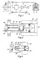
- this method consists in supplying, via a pressure regulator 1, a pneumatic circuit comprising a first branch 2 provided with an inlet nozzle 3 and a measuring pin 4 likely for example to be introduced into a bore 5 whose diameter must be measured, as well as a second branch 6 provided with an inlet nozzle 7 opening into a reference nozzle 8, the flow rate of which can be adjustable.
- a pressure transducer 9 connected between branches 2 and 6 delivers an electrical signal representative of the difference in pressures prevailing in these branches, which is amplified by an amplifying device 10 before being supplied for example to an indicating device 11.
- the known systems are generally very sensitive to vibrations, due to the presence of mobile mechanical elements in the transducer, which can lead to disturbances or errors in the measurement. This is why it is necessary to house most of the elements of the pneumatic circuit, including the inlet and reference nozzles as well as the transducer in a separate housing, to which the measuring pin is connected by a conduit, including a volume significant air, which causes a significant extension of the time constant of the measuring device.
- the object of the present invention is to propose an improvement of the known devices, which makes it possible to considerably reduce the measurement noise, as well as the time constant and the sensitivity to vibrations, while allowing simple adjustment. and independent of the sensitivity of the device and zero of the output signal.
- FIG. 2 there is shown a measuring pin 12 whose end is engaged in the bore 13 of a part 14.
- the pneumatic measuring device is fully included in the spindle 12, and in particular it comprises a first branch 15 delimited by an inlet nozzle 16 and two measuring nozzles 17 arranged symmetrically on either side of the cylindrical end 18 of the spindle 12, facing the walls of the bore 13 to be measured.
- a second branch 19 is delimited by an inlet nozzle 20, and a reference nozzle 21, which can be adjustable.
- the pressure difference between. the branches 15 and 19 is picked up by a differential pressure transducer with semiconductor element 22, electrically connected to a connection terminal 23 making it possible to supply the transducer 22, and to collect the signal representative of the differential pressure between the branches 15 and 19 from the pneumatic circuit.
- a line 24 makes it possible to connect the inlet nozzles 16 and 20 to an external regulated pressure source.
- the semiconductor element differential pressure transducer 22 used in the measuring device essentially consists of a semiconductor wafer in which a membrane has been produced by chemical machining processes, as well as a piezo bridge. resistors formed on the membrane and amplifying elements.
- Such pressure transducers, and their manufacture are described for example in patent application FR-A-2 266 314, and they are distributed in particular by the companies known as the National Semi-conductor Corporation, or Honeywell.
- the small volume of the transducer 22 makes it very easy to integrate it into the measuring pin 12, so as to reduce the volume of air circulating in the pneumatic circuit extremely considerably.
- the branches 15 and 19 of the pneumatic circuit whose pressures are compared are arranged in close proximity to one another, and therefore subjected to the same temperature, which largely eliminates the influences of temperature.
- the reference nozzle 21 it has appeared advantageous to dimension the reference nozzle 21 in such a way that the differential pressure between the two branches is zero when the dimensions of the part 14 reach their set value.
- the stability and the precision of the measurement of the dimensions are maximum when this differential pressure is close to zero and the preceding arrangement makes it possible to ensure that the maximum precision is obtained, for example during machining, when the we are approaching the set dimensions.
- FIG. 3 a variant construction of the measuring pin 12 of FIG. 2 is shown, in which the end of this pin is provided with a removable end-piece 25.
- This end-piece is for example screwed at the end of pin 12, and it has a pipe 26 for connecting two end nozzles 27 to the inlet nozzle 16 and of the transducer 22.
- the same measuring pin 12 with the resulting advantages, can be used to measure the diameter of a small bore 28 in a part 29.
- An annular seal 30 seals the first branch of the pneumatic circuit.
- FIG 4 there is shown a pin 12 identical to that of Figure 2, but which is adapted so as to allow the correction of a bore matched to the dimensions of a determined shaft 35.
- a ring is used 36, a conventional type, which is the equivalent of a measuring pin to measure the diameter of a tree.
- stirrups which only partially surround the measured shaft, but which would fulfill the same function.
- Such devices are defined for example in standard DIN 2271, part 2.
- the measuring ring 36 is connected directly by a pipe 37 to the end of the branch 15 of the pneumatic circuit of the device included in the spindle 12.
- the transducer 22 allows a comparative measurement of the diameters of the bore 13 and that of the shaft 35.
- FIG. 5 there is shown schematically a control circuit of the differential pressure transducer used in the device of the invention.
- This transducer is shown diagrammatically in the frame in dotted lines 40 by a bridge of piezoresistors 41 which are supplied via a supply 47, preferably a current source.
- An operational amplifier 42 one of the inputs of which is controlled by means of an adjustable potentiometer 43 makes it possible to adjust the zero of the output signal, while the gain of the amplification is defined by the potentiometer 44 which acts on the amplifier 45, at the output 46 from which the signal representative of the dimension measured can be collected.
- the dimensional and dynamic characteristics of the measurement device according to the invention allow it to be applied to many types of measurements in the field of machining of parts.
- it is particularly well suited for being mounted inside the workpiece headstock of an internal grinding machine, and kinematically connected to the tool headstock, so as to measure the diameter of the bore of the part rectified during each oscillation of the tool, and thus allow to continuously adjust the advance of the grinding wheel, throughout the grinding operation, and to stop it when the nominal dimension of the bore is reached.
Landscapes
- Physics & Mathematics (AREA)
- General Physics & Mathematics (AREA)
- Measuring Arrangements Characterized By The Use Of Fluids (AREA)
Claims (5)
Applications Claiming Priority (4)
| Application Number | Priority Date | Filing Date | Title |
|---|---|---|---|
| CH677682 | 1982-11-22 | ||
| CH6776/82 | 1982-11-22 | ||
| FR8220529A FR2537269A1 (fr) | 1982-12-06 | 1982-12-06 | Dispositif de mesure pneumatique des dimensions d'une piece |
| FR8220529 | 1982-12-06 |
Publications (2)
| Publication Number | Publication Date |
|---|---|
| EP0109936A1 EP0109936A1 (de) | 1984-05-30 |
| EP0109936B1 true EP0109936B1 (de) | 1987-09-30 |
Family
ID=25700161
Family Applications (1)
| Application Number | Title | Priority Date | Filing Date |
|---|---|---|---|
| EP19830810525 Expired EP0109936B1 (de) | 1982-11-22 | 1983-11-16 | Pneumatische Einrichtung zur Massbestimmung eines Werkstücks |
Country Status (2)
| Country | Link |
|---|---|
| EP (1) | EP0109936B1 (de) |
| DE (1) | DE3373941D1 (de) |
Families Citing this family (5)
| Publication number | Priority date | Publication date | Assignee | Title |
|---|---|---|---|---|
| FR2668823B1 (fr) * | 1990-11-05 | 1992-12-31 | Meseltron Sa | Dispositif de mesure des dimensions d'une piece. |
| JP4840631B2 (ja) | 2001-08-29 | 2011-12-21 | 株式会社東京精密 | 内径測定方法及び装置 |
| RU2301402C1 (ru) * | 2005-12-06 | 2007-06-20 | Закрытое акционерное общество "РС-Лизинг" | Способ измерения диаметра отверстий и устройство для его осуществления |
| CN108050915B (zh) * | 2017-12-14 | 2020-03-06 | 中国航发沈阳发动机研究所 | 一种用于测量发动机可调喷口内径的加载测量系统 |
| CN114407060B (zh) * | 2022-02-21 | 2023-08-22 | 河南科技大学 | 用于圆柱类零件外径气动测量的主被动柔顺机械手装置 |
Family Cites Families (3)
| Publication number | Priority date | Publication date | Assignee | Title |
|---|---|---|---|---|
| US3069899A (en) * | 1960-09-13 | 1962-12-25 | Gen Motors Corp | Pneumatic gauges for measuring bore diameters of workpieces |
| US3494078A (en) * | 1966-06-01 | 1970-02-10 | Katsumi Miyamoto | Automatic sizing device of internal grinder |
| US4088009A (en) * | 1973-06-09 | 1978-05-09 | Akira Fukuda | Air micrometer |
-
1983
- 1983-11-16 EP EP19830810525 patent/EP0109936B1/de not_active Expired
- 1983-11-16 DE DE8383810525T patent/DE3373941D1/de not_active Expired
Also Published As
| Publication number | Publication date |
|---|---|
| EP0109936A1 (de) | 1984-05-30 |
| DE3373941D1 (en) | 1987-11-05 |
Similar Documents
| Publication | Publication Date | Title |
|---|---|---|
| EP3304022B1 (de) | Druckmessvorrichtung mit verbesserter zuverlässigkeit und zugehöriges kalibrierungsverfahren | |
| EP0469991B1 (de) | Fühler für Luftfahrzeuge zum Messen der aerodynamischen Parameter der umgebenden Strömung | |
| US20140168659A1 (en) | Micromachined metal diaphragm based fabry-perot fiberoptic sensor system and data processing involving the same | |
| FR2839152A1 (fr) | Capteur de presion avec une membrane resistant a la corrosion | |
| EP0109936B1 (de) | Pneumatische Einrichtung zur Massbestimmung eines Werkstücks | |
| WO1990001153A1 (fr) | Capteur de pression, procede de production et dispositif hydraulique pourvu de ce capteur | |
| WO2006070109A1 (fr) | Filtre muni d’un detecteur de colmatage et d' un ensemble a la detection da la presence d ' un element filtrant a l ' interieur de celui-ci | |
| US4538449A (en) | Pneumatic measuring device for measuring workpiece dimension | |
| FR2571845A1 (fr) | Systeme de mesure de distance inductif sans contact, notamment pour la detection du niveau d'un bain de metal liquide | |
| EP0484764A1 (de) | Vorrichtung zum Messen der Dimensionen eines Objektes | |
| CN114235229B (zh) | 一种基于压电陶瓷传感器的超精密切削准静态力检测方法 | |
| FR2537269A1 (fr) | Dispositif de mesure pneumatique des dimensions d'une piece | |
| EP0100716B1 (de) | Koordinatentaster mit einem Laser | |
| FR3059095B1 (fr) | Debitmetre thermique massique | |
| EP0932036B1 (de) | Permeameter mit grossem Messbereich | |
| FR2459462A1 (fr) | Dynanometre a diaphragmes | |
| EP0468829A1 (de) | Gerät zur Qualitätsüberwachung des Oberflächenzustandes eines Gegenstandes | |
| CN110926684A (zh) | 一种耐350℃高温压力传感器的转接环结构 | |
| FR2651313A1 (fr) | Debitmetre d'air pour un moteur a combustion interne et procede pour sa fabrication. | |
| FR2671846A1 (fr) | Vanne a detection de contrainte. | |
| EP0194937B1 (de) | Kolbentyp-Drucksensor | |
| FR2640106A1 (fr) | Dispositif et procede pour corriger le signal de sortie d'un hydrophone en en eliminant la composante hydrostatique | |
| FR3037397A1 (fr) | Dispositif de detection de pression a decouplage mecanique | |
| WO1992021951A1 (fr) | Procede et dispositif d'etalonnage de couplemetres et couplemetre compact adapte au dispositif | |
| FR3074579B1 (fr) | Procede de fabrication simplifie d'un capteur de pression differentielle |
Legal Events
| Date | Code | Title | Description |
|---|---|---|---|
| PUAI | Public reference made under article 153(3) epc to a published international application that has entered the european phase |
Free format text: ORIGINAL CODE: 0009012 |
|
| AK | Designated contracting states |
Designated state(s): CH DE GB IT LI SE |
|
| 17P | Request for examination filed |
Effective date: 19840818 |
|
| 17Q | First examination report despatched |
Effective date: 19860124 |
|
| R17C | First examination report despatched (corrected) |
Effective date: 19860618 |
|
| GRAA | (expected) grant |
Free format text: ORIGINAL CODE: 0009210 |
|
| AK | Designated contracting states |
Kind code of ref document: B1 Designated state(s): CH DE GB IT LI SE |
|
| ITF | It: translation for a ep patent filed | ||
| REF | Corresponds to: |
Ref document number: 3373941 Country of ref document: DE Date of ref document: 19871105 |
|
| GBT | Gb: translation of ep patent filed (gb section 77(6)(a)/1977) | ||
| PLBE | No opposition filed within time limit |
Free format text: ORIGINAL CODE: 0009261 |
|
| STAA | Information on the status of an ep patent application or granted ep patent |
Free format text: STATUS: NO OPPOSITION FILED WITHIN TIME LIMIT |
|
| 26N | No opposition filed | ||
| PGFP | Annual fee paid to national office [announced via postgrant information from national office to epo] |
Ref country code: GB Payment date: 19911021 Year of fee payment: 9 |
|
| PGFP | Annual fee paid to national office [announced via postgrant information from national office to epo] |
Ref country code: SE Payment date: 19911112 Year of fee payment: 9 |
|
| PGFP | Annual fee paid to national office [announced via postgrant information from national office to epo] |
Ref country code: DE Payment date: 19911119 Year of fee payment: 9 |
|
| PGFP | Annual fee paid to national office [announced via postgrant information from national office to epo] |
Ref country code: CH Payment date: 19911120 Year of fee payment: 9 |
|
| ITTA | It: last paid annual fee | ||
| PG25 | Lapsed in a contracting state [announced via postgrant information from national office to epo] |
Ref country code: GB Effective date: 19921116 |
|
| PG25 | Lapsed in a contracting state [announced via postgrant information from national office to epo] |
Ref country code: SE Effective date: 19921117 |
|
| PG25 | Lapsed in a contracting state [announced via postgrant information from national office to epo] |
Ref country code: LI Effective date: 19921130 Ref country code: CH Effective date: 19921130 |
|
| GBPC | Gb: european patent ceased through non-payment of renewal fee |
Effective date: 19921116 |
|
| REG | Reference to a national code |
Ref country code: CH Ref legal event code: PL |
|
| PG25 | Lapsed in a contracting state [announced via postgrant information from national office to epo] |
Ref country code: DE Effective date: 19930803 |
|
| EUG | Se: european patent has lapsed |
Ref document number: 83810525.2 Effective date: 19930610 |