EP0109807A1 - Zinc-bromine battery with long term stability - Google Patents
Zinc-bromine battery with long term stability Download PDFInfo
- Publication number
- EP0109807A1 EP0109807A1 EP83306866A EP83306866A EP0109807A1 EP 0109807 A1 EP0109807 A1 EP 0109807A1 EP 83306866 A EP83306866 A EP 83306866A EP 83306866 A EP83306866 A EP 83306866A EP 0109807 A1 EP0109807 A1 EP 0109807A1
- Authority
- EP
- European Patent Office
- Prior art keywords
- electrolyte
- electrode
- face
- cell
- anode
- Prior art date
- Legal status (The legal status is an assumption and is not a legal conclusion. Google has not performed a legal analysis and makes no representation as to the accuracy of the status listed.)
- Withdrawn
Links
Images


Classifications
-
- H—ELECTRICITY
- H01—ELECTRIC ELEMENTS
- H01M—PROCESSES OR MEANS, e.g. BATTERIES, FOR THE DIRECT CONVERSION OF CHEMICAL ENERGY INTO ELECTRICAL ENERGY
- H01M10/00—Secondary cells; Manufacture thereof
- H01M10/36—Accumulators not provided for in groups H01M10/05-H01M10/34
- H01M10/365—Zinc-halogen accumulators
-
- B—PERFORMING OPERATIONS; TRANSPORTING
- B60—VEHICLES IN GENERAL
- B60L—PROPULSION OF ELECTRICALLY-PROPELLED VEHICLES; SUPPLYING ELECTRIC POWER FOR AUXILIARY EQUIPMENT OF ELECTRICALLY-PROPELLED VEHICLES; ELECTRODYNAMIC BRAKE SYSTEMS FOR VEHICLES IN GENERAL; MAGNETIC SUSPENSION OR LEVITATION FOR VEHICLES; MONITORING OPERATING VARIABLES OF ELECTRICALLY-PROPELLED VEHICLES; ELECTRIC SAFETY DEVICES FOR ELECTRICALLY-PROPELLED VEHICLES
- B60L50/00—Electric propulsion with power supplied within the vehicle
- B60L50/50—Electric propulsion with power supplied within the vehicle using propulsion power supplied by batteries or fuel cells
- B60L50/60—Electric propulsion with power supplied within the vehicle using propulsion power supplied by batteries or fuel cells using power supplied by batteries
- B60L50/64—Constructional details of batteries specially adapted for electric vehicles
-
- H—ELECTRICITY
- H01—ELECTRIC ELEMENTS
- H01M—PROCESSES OR MEANS, e.g. BATTERIES, FOR THE DIRECT CONVERSION OF CHEMICAL ENERGY INTO ELECTRICAL ENERGY
- H01M6/00—Primary cells; Manufacture thereof
- H01M6/42—Grouping of primary cells into batteries
- H01M6/46—Grouping of primary cells into batteries of flat cells
- H01M6/48—Grouping of primary cells into batteries of flat cells with bipolar electrodes
-
- Y—GENERAL TAGGING OF NEW TECHNOLOGICAL DEVELOPMENTS; GENERAL TAGGING OF CROSS-SECTIONAL TECHNOLOGIES SPANNING OVER SEVERAL SECTIONS OF THE IPC; TECHNICAL SUBJECTS COVERED BY FORMER USPC CROSS-REFERENCE ART COLLECTIONS [XRACs] AND DIGESTS
- Y02—TECHNOLOGIES OR APPLICATIONS FOR MITIGATION OR ADAPTATION AGAINST CLIMATE CHANGE
- Y02E—REDUCTION OF GREENHOUSE GAS [GHG] EMISSIONS, RELATED TO ENERGY GENERATION, TRANSMISSION OR DISTRIBUTION
- Y02E60/00—Enabling technologies; Technologies with a potential or indirect contribution to GHG emissions mitigation
- Y02E60/10—Energy storage using batteries
-
- Y—GENERAL TAGGING OF NEW TECHNOLOGICAL DEVELOPMENTS; GENERAL TAGGING OF CROSS-SECTIONAL TECHNOLOGIES SPANNING OVER SEVERAL SECTIONS OF THE IPC; TECHNICAL SUBJECTS COVERED BY FORMER USPC CROSS-REFERENCE ART COLLECTIONS [XRACs] AND DIGESTS
- Y02—TECHNOLOGIES OR APPLICATIONS FOR MITIGATION OR ADAPTATION AGAINST CLIMATE CHANGE
- Y02T—CLIMATE CHANGE MITIGATION TECHNOLOGIES RELATED TO TRANSPORTATION
- Y02T10/00—Road transport of goods or passengers
- Y02T10/60—Other road transportation technologies with climate change mitigation effect
- Y02T10/70—Energy storage systems for electromobility, e.g. batteries
Definitions
- the present invention relates to a zinc-bromine secondary battery.
- the battery with which the invention is concerned employs an array of cells connected in series by means of intervening bipolar electrodes and employs a single recirculating electrode conducted by manifolds between an external storage tank and the several cells of the array. It is an object of the invention to provide a cell of the aforesaid kind in which long term system degradation is avoided, self-discharge is limited, the environmental hazards associated with the use of bromine are minimised and the internal resistance may be made acceptably low.
- the invention provides a secondary battery using the zinc-bromine electrocouple comprising a multiplicity of electrodes disposed in a linear array and defining therebetween cell spaces having confronting anode and cathode faces with the electrodes intermediate the ends of .
- the array each defining an anode face in one cell space and a cathode face in an adjoining cell space with the anode and cathode faces in electrically conductive relationship so that the intermediate electrodes connect the several cell spaces in series, a single electrolyte which is partly in the cell spaces and partly in a reservoir and means for recirculating the electrolyte continuously between the cell spaces and the reservoir so that it flows longitudinally through the cell spaces, characterised in that the cathode face of each intermediate electrode has a coherent porous mass of binder-free charcoal particles of stable dimensions and configuration lightly compressed into electrical contact with it and with each other, spacer means holding said particles off from contact with the confronting anode face and in that means divides the flow path through each cell space into a major flow path which bypasses the charcoal particles and in which there is a faster higher throughput electrolyte flow and a minor flow path in which electrolyte branches off from the major path to flow slowly through the mass of porous material and rejoin the main flow.
- a secondary battery comprising a multiple cell array and circulation of electrolyte through the cells and around a substantially closed liquid loop circulating system outside the cells.
- the electrolyte comprises aqueous zinc-bromide solution per se, or with resistance depressing and/or plating brightener additives and/or bromine complexing additives to suppress bromine volatility.
- Each cell is of a single electrolyte type; that is, no means are provided to split the cell into two electrolyte compartments with distinctly different electrolyte flow therein.
- the latter artifact is often employed in the prior art to prevent parasitic chemical reaction between bromine and zinc.
- a pseudo two- compartment structure is employed in each cell by creating a low flow pool of electrolyte in a charcoal containing region at each cathode face by a membrane separating such pool from a high flow rate pool.
- Each cell comprises a positive electrode (cathode) with porous surfacing to store molecular bromine and a negative electrode (anode) which serves as a substrate for zinc deposition.
- the reactions occur, proceeding primarily to the right, with bromine adsorption at the cathode and zinc plating at the anode.
- Secondary reactions simultaneously occurring along with (I) and (II) during discharge and/or charge involve partial electrolysis of additives or of the salt provided (eg. to decrease resistivity) and/or of the polyethylene glycol or tetra ammonium halides which may have. been provided to suppress bromine volatility, if any, in the electrolyte and to a small extent of the water itself and hydrolysis, including hydrolysis of bromine.
- the main reactions (I) and (II) proceed to. return zinc and bromine to solution. Gases formed on battery operation tend to escape. Bromine vapour pressure goes from 100 mm Hg at 0°C to about 600 mm at 50°C.
- the secondary reactions are negligible or sufficiently countered through the system of the present invention and that they will not prevent repeatable charge and discharge over thousands of cycles. In some instances, these secondary reactions are promoted and used to maintain system stability.
- active carbon embedded in the electrode positive electrode side, at least catalyses the hydrolysis of molecular bromine and liberates oxygen from the water, to compensate inevitable drift of system pH.
- the electrodes are provided and cells are defined by an array of intermediate electrode assemblies with opposing anode and cathode faces, described further below in this summary.
- the present invention preferably provides a construction and arrangement such that zinc bromide molarity of the electrolyte is 0.5 to 1.5 at full charge and 2 to 4 at deep discharge.
- This low molarity throughout cycling limits safety hazards, holds resistivity to an acceptable range and limits zinc attack in a single cell.
- This low molarity corresponds to low density (1.06 gm/cc at 0.5 molar, 1.72 gm/cc at 4.0).
- prior art systems range over 4 molar and over 2.0 gm/cc at some stage of cycling.
- Each cell has the form of a thin volume defined by confronting anode and cathode electrodes, each preferably having an aspect ratio (height to width) of more than 2.0, but less than 10.0, and preferably arranged with an electrical series, hydraulic parallel array of such cells utilising mid-bipolar electrodes and using end electrodes with external connections.
- the mid and end electrode edges may be sealed to prevent cell to cell leakage of electrolyte and also to prevent leakage to the exterior of the cell array.
- a circulating system for the array comprises intake and outlet manifolds, a circulating loop, a pump and a, preferably small, storage reservoir, a heat exchanger, vent means, drain means, and electrolyte measuring means.
- the drain feature allows quick emptying of the cell array in case of catastrophic electrical or chemical runaway condition therein.
- the limited recirculation of the system of the present invention together with the array construction thereof and means for assuring uniform flow and reaction conditions, provides uniform temperature distribution through the device and uniform reactant supply, prevention of zinc dendrites shorting out from anode to cathode, reduced polarisation and a means of electrolyte measurement and modification (physically or chemically).
- the end and mid-electrodes have, eg. minimal thicknesses, on the order of 0.10" to 0.030" (0.25 to 0.076 cms.) respectively and inter-electrode spacing of about .05" (0.12 cms.) for a high power version and spacing of up to about 0.30" (0.76 cms) for a low power version. They afford low resistances, on the order of milliohms even in 10-100 cell arrays (for 6 to 110 volt devices). For most practical purposes electrode edge lengths of 20 by 40 inches (50 by 101 cms.) to as low as 2 by 4 inches (5 by 10 cms.) will be utilised.
- the electrodes are hot pressed plastic substrates (preferably polyvinyl/chloride-graphite composites) with face particles of porous carbon bonded to the substrate.
- the end electrodes have metal screens adhered to their substrates or encapsulated in such substrates.
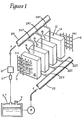
- FIG. 1 there is shown a battery 10 with end electrode assemblies constituting an end anode 12-and cathode 14 and mid-electrodes 16 forming cells (with spacing ported-membrane screen assemblies 17) in an electrical series, fluid parallel array.
- An inlet manifold 22 and outlet manifold 24 provide flow through the cells of electrolyte as indicated by arrows F.
- An external flow system comprises a pump P, and storage tank S.T. with gas vent V, a monitoring instrument I and heat exchanger Q. Screens 5 are affixed to (or encapsulated within) the end electrode assemblies.
- a leak proof casing preferably of inert plastic (eg. an epoxy encapsulation), is applied to the exterior of the battery 10 of Figure 2 (but is not shown in such figure).
- the tributaries are very thin compared to the manifolds and are constructed such that cell to cell current leakage of the battery produces less than 1% degradation of current generating efficiency.
- FIGs 2-4 show one of the mid-electrode assemblies 16 in greater detail. within the epoxy encapsulation covering 18 of the battery.
- Each such assembly comprises an electrode substrate 26, which is a planar conductive carbon/plastic composite of low lateral (perpendicular to the plane of the substrate) and low sheet resistivity.
- Such substrates have oppositng faces usable as anode and cathode faces, which faces may be of identical form, or different forms as hereinafter described.
- the anode face is designated 26A and the cathode face 26C in Figures 3 and 4.
- the batteries 10 will - in practice - comprise at least ten and in many cases substantially over twenty such electrode assemblies 16 in a long array between the end electrodes 12 and 14.
- the electrode substrate of the end electrode assembly 12 provides anode face usage only and that the electrode substrate of the end electrode assembly 14 provides only cathode face usage.
- the electrode substrates are preferably made of a hot pressed mixture of graphite and bromine resistant plastics, preferably polyvinylidene fluoride [but less expensive resins can be employed for some applications, eg. acrylonitrile-butadiene-styrene (ABS) or polyvinylchloride (PVC)].
- Each anode face 16A preferably has a surface enhancement ratio (actual surface area to planar projection area) of at least 3:1, preferably over 5:1.
- Such enhancement helps assure uniformity of zinc plating on the anode face during battery charging and good adhesion of the plating.
- the enhancement may be provided by diverse means, eg. cross-hatch scoring of a pressed sub- strate or moulding in ridge or hump patterns or embedding particles in the surface (preferably particles of such low conductivity relative to the substrate -- a fraction of 1/1000th or less -- as to constitute a virtual insulator by comparison). It is also desirable to similarly enhance the surface of cathode face 26C; but in such case the particles in the surface (if that approach is used) would be conductive.
- the cathode face 26C is covered with unbonded activated charcoal in an amount and depth proportioned to the battery's energy storage specifications.
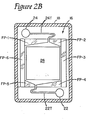
- the charcoal is retained within a rectangular curbing frame 26F, overlaid with a polypropylene screen cover 26P which is in turn overlaid with a membrane 26M and a spacer screen 26S with ribs 26B.
- the membrane is provided with vent holes 26H at the bottom as shown in Figure 2A and also at the top. Such hole arrays 26H span the width of membrane 26M at top and bottom. They allow electrolyte flow to enter from the main cell channel to the zone containing the charcoal and equalise pressure on initial admission of flow to the cell.
- a preferred material of the cover 26P is a Pellon brand non-woven fabric, heat bonded (at fibre cross-overs) using polypropylene fibres so constructed to form a non- degrading porous mat. It maintains chemical inertness, structural integrity and mechanical strength under cell operation conditions and has attributes of low resistance, light weight and low cost.
- a preferred material of the membrane 26M is W.R. Grace Co's Daramic brand microporous polyethylene sheet.
- a preferred material for surfacing anode face 26A is a silicon dioxide particle layer which serves to anchor the zinc plating and makes the anode surface more wettable. Active carbon (preferably Barnaby-Cheney's UU or OL grades by Calgon Co. type ⁇ ) is pressed into the cathode face 16C to enhance contact . between substrate 16B and the charcoal particles.
- the electrode substrates are held in holders 16H which are frames, preferably made of PVC or polyurethane.
- the carbon particle holding region is defined by a frame 26 F which may be in an inner edge of holder 26H or may comprise separate framing pieces inserted in a rectangular arrangement to define the carbon particle mass (see FP-1 - FP-6 in Figure 2B).
- an electrode substrate plate 26 is employed with active surface particles embedded only in region 26" of its cathode face.
- the carbon particle mass is held and slightly compressed in the space defined by such framing and the overlying covers 26P, 26M, 26S with ribs 26R and the substrate 26. No binders are used and the carbon is amply filled in such space and lightly compressed by the repeating arrangement of items 26C, 26P, 26M, 26S, 26C, 26P, 26M, 26S, etc., between end electrodes 12 and 14.
- Such compression arrangement affords reliable spacing and retention of elements 26, 26P, 26M, 26S, none of which would be rigid per se, but behave as though rigid in a stacked array between 12 and 14 to help assure uniformity of electrolyte flow between electrodes and avoidance of electrodes randomly sagging towards each other.
- a well W and dome D are provided between adjacent electrode assemblies below and above each electrode substrate 26 through appropriate cutaways of holders 16H to define areas outside of electrode zones - an escaping gas region in dome D and an escaping liquid region (providing a region for flaked-off particles of zinc coatings) in well W.
- the dome and wells are V-shaped for assuring complete capture and their apexes are offset for optimising uniformity of electrolyte flow from the tributary 22T which feeds well W to the tributary 24T which is the outlet for exiting liquid (and any escaping gases), and additionally offset in a way that allows maximising lengths of such tributaries in the limited spaces of holder 16H.
- a sealant 16S preferably of epoxy, surrounds each electrode substrate 26 to secure it to the holder 16H and assure that there is no leakage around such edges (to avoid chemical reactions, which would parasitically degrade the main electrochemical reactions of the battery).
- the electrodes are constructed of graphite and fluorocarbon binders, a material not easily cemented or glued. Except for solvent welding of two identically materialled components such as PVC or ABS, cementing or adhering two parts together may be unreliable and cementing two large areas or long length parts with glues, epoxies, etc. in a manner which will not develop fluid leaks is not practical.
- the electrode edges are dipped into a tray type mould for casting of epoxy. Each of the four edges is thus “potted” by suspending the array or stack about 0.5 inches (1.2 cms.) above the bottom of the shown mould. Epoxy is poured into the mould up to a predetermined level into the stack.
- Electrolyte compostions for the ZnBr 2 system have a range of concentrations and ingredients depending upon the properties desired.
- High drain rate (high power density) units employ electrolyte of lowest available resistance resulting in the regime of low resistivity such as shown in Figure 7.
- High energy capacity module designs will tend to use relatively high concentrations of ZnBr 2 salt to minimise water weight and, in some designs, complexing agents for increased capacity and charge retention and a brightener additive for improved zinc plating quality (lower dendritic growth).
- compositions are:
- pH stabilisation or balance of electrolyte is achieved automatically in cells as described herein because of the hydrolysis of Br 2 in the presence of active carbon.
- the carbon catalyses the reaction: and the oxygen is released from the HBrO at a later time thus balancing the loss of H 2 at the zinc electrode.
- the hydrogen loss at the zinc or negative electrode is via the reaction:
- the pH reaches a relatively stable range of value of between 2 and 4 during cell operation depending upon temperature, state of charge and electrolyte composition.
- the last reaction above represents a coulombic loss in efficiency and should be minimised in any event.
- Electrolyte pH control is an important feature of use of active carbon electrodes. Since the pH of ZnBr 2 solution is acidic eg., in the range of 2 - 4 during normal cell operation, H 2 gas is generated at the surface of the negative electrode. thus regenerating H+ ions which are lost at the negative electrode and with the eventual liberation of 0 2 . Hence, there is no need for making other ancillary provisions for pH regulation as there is in other prior art systems.
- pH stabilisation or balance of electrolyte is achieved automatically in these cells because of the hydrolysis of Br 2 in the presence of active carbon.
- the carbon catalyses the reaction: and the oxygen is released from the HBrO at a later time thus balancing the loss of H 2 at the zinc electrode.
- the hydrogen loss at the zinc or (+) electrode is via the reaction:
- the pH reaches a relatively stable range of value of between land 4 during cell operation depending upon temperature, state of charge and electrolyte compostion.
- the last reaction above represents a coulombic loss in efficiency and should be minimised in any event.
- the electrode assemblies are manufactured as follows:
- the resistance of a channel is expressible as ohms
- ⁇ /l 0.20 amps/30.6 inches 0.0065 in.
- the minimum necessary length,xL, per tributary is
- tributary lengths and areas may be. similarly computed via the above relationships for different design criteria of permissible losses, discharge current and stack size, N.
- a regenerable vent trap may be provided in reservoir R for entrapment of free bromine traces escaping from the electrolyte through the O2 and H 2 venting of the reservoir.
- Data obtained for equilibrium vapour pressure of Br 2 in the presence of adsorbed Br 2 on active carbon surfaces shows that for 0.1 to 0.2 gm of Br 2 per gram of carbon (activated coconut charcoal) the partial pressure of Br 2 is significantly less than 10- 3 mm. of Hg. This gives a presence of 1 part per million of Br 2 in a vent trap with active carbon at rated saturation of 0.1 to 0.2 gm. of adsorbed Br 2 . Partial pressures of much less than 0.01 ppm of Br 2 are maintainable even in the worst rated conditions for system operation.
- a regenerable trap eliminates the need to add HBr to the system periodically and to replace the activated carbon.
- the trap may be located above the electrolyte level in the reservoir R.
- a temperature sensor for system control may be located below the liquid levels for direct electrolyte temperature measurement.
- a control unit I ( Figure 1) sensing the cut-off temperature switches off the power to the motor of pump D. Electrolyte drains backwards through the well W, the pump D into the storage tank S. Another more rapid approach to draining may be employed in which the pump D is bypassed by a large drain line into the reservoir and not only is the pump motor switched off when the temperature becomes too high, but a solenoid activated or back pressure release valve opens into the drain. Positive displacement pumps could then be used in such a configuration.
- the electrolyte flow rates for a bipolar array of 17 electrodes with plate areas of 200 sq. in. (1290 sq. cms.) is between 1 and 2 gallons/minute (4.5 to 9 litres/minute) and a pressure head of 0.5 to 1.0 psi (3.44 to 6.9 K Pa). Slower flow rates may be employed.
- Batteries made as described above were repeatedly cycled 25 times or more through constant charging current at 8 amperes and constant current discharge at 6, 8, 10 or 12 amperes (Amp). No degradation of the voltage-time characteristics of the discharge cycles was noted over the course of such repeated cycling.
- the voltage-time characteristics are shown in Figure 5 where voltage (volts) at the terminals (screens S in Figure 1) is plotted against time (hours) of discharge cycle. Electrolye pH, temperature and pressure drops were continuously measured and found to remain in normal circuits.
- the test batteries were one kilowatt hour systems comprising 12 cells with 140 sq. in.
Abstract
A zinc-bromine secondary battery having a recirculating electrolyte uses an array of cells (14,15,16) in series with a parallel fluid flow through the several cell spaces along the confronting electrodes. The intermediate electrodes (16) are bipolar with their cathode face (26C) having a coherent porous mass of binder-free charcoal particles of stable dimensions and configuration lightly pressed into electrical contact with it and with each other. Spacer means (26C) holds the particles off from contact with the confronting anode face. A single electrolyte flows through each cell with a flow path divided so that a high speed and throughput major portion bypasses the charcoal particles and a minor portion branches therethrough. The zinc-bromine molarity of the electrolyte is preferably 0.5-1.5 at full charge and 2 to 4 at deep discharge and preferably only about 1% by weight of the molecular bromine present is in circulation with the remainder trapped in the electrode assemblies at all times. The cell has a minimum long-term system degradation, has limited self-discharge and has low environmental hazards.
Description
- The present invention relates to a zinc-bromine secondary battery.
- The battery with which the invention is concerned employs an array of cells connected in series by means of intervening bipolar electrodes and employs a single recirculating electrode conducted by manifolds between an external storage tank and the several cells of the array. It is an object of the invention to provide a cell of the aforesaid kind in which long term system degradation is avoided, self-discharge is limited, the environmental hazards associated with the use of bromine are minimised and the internal resistance may be made acceptably low.
- Broadly stated the invention provides a secondary battery using the zinc-bromine electrocouple comprising a multiplicity of electrodes disposed in a linear array and defining therebetween cell spaces having confronting anode and cathode faces with the electrodes intermediate the ends of.the array each defining an anode face in one cell space and a cathode face in an adjoining cell space with the anode and cathode faces in electrically conductive relationship so that the intermediate electrodes connect the several cell spaces in series, a single electrolyte which is partly in the cell spaces and partly in a reservoir and means for recirculating the electrolyte continuously between the cell spaces and the reservoir so that it flows longitudinally through the cell spaces, characterised in that the cathode face of each intermediate electrode has a coherent porous mass of binder-free charcoal particles of stable dimensions and configuration lightly compressed into electrical contact with it and with each other, spacer means holding said particles off from contact with the confronting anode face and in that means divides the flow path through each cell space into a major flow path which bypasses the charcoal particles and in which there is a faster higher throughput electrolyte flow and a minor flow path in which electrolyte branches off from the major path to flow slowly through the mass of porous material and rejoin the main flow.
- Energy storage is provided by a secondary battery comprising a multiple cell array and circulation of electrolyte through the cells and around a substantially closed liquid loop circulating system outside the cells. The electrolyte comprises aqueous zinc-bromide solution per se, or with resistance depressing and/or plating brightener additives and/or bromine complexing additives to suppress bromine volatility.
- Each cell is of a single electrolyte type; that is, no means are provided to split the cell into two electrolyte compartments with distinctly different electrolyte flow therein. The latter artifact is often employed in the prior art to prevent parasitic chemical reaction between bromine and zinc. However, a pseudo two- compartment structure is employed in each cell by creating a low flow pool of electrolyte in a charcoal containing region at each cathode face by a membrane separating such pool from a high flow rate pool.
- Each cell comprises a positive electrode (cathode) with porous surfacing to store molecular bromine and a negative electrode (anode) which serves as a substrate for zinc deposition. During charging the reactions:


- It is found that the secondary reactions are negligible or sufficiently countered through the system of the present invention and that they will not prevent repeatable charge and discharge over thousands of cycles. In some instances, these secondary reactions are promoted and used to maintain system stability. For instance, active carbon embedded in the electrode (positive electrode side, at least) catalyses the hydrolysis of molecular bromine and liberates oxygen from the water, to compensate inevitable drift of system pH. The electrodes are provided and cells are defined by an array of intermediate electrode assemblies with opposing anode and cathode faces, described further below in this summary.
- The present invention preferably provides a construction and arrangement such that zinc bromide molarity of the electrolyte is 0.5 to 1.5 at full charge and 2 to 4 at deep discharge. This low molarity throughout cycling limits safety hazards, holds resistivity to an acceptable range and limits zinc attack in a single cell. This low molarity corresponds to low density (1.06 gm/cc at 0.5 molar, 1.72 gm/cc at 4.0). In contrast prior art systems range over 4 molar and over 2.0 gm/cc at some stage of cycling.
- It is desirable to the present invention to limit the volume of bromine in circulation outside the cell to a small per cent of total molecular bromine of the system. At least a substantial majority of molecular bromine should be in the cell array trapped in electrode assembies, at all times, with less than about 1/100th (by weight), preferably less than 1/300th in the external circulating loop. During discharge most of the bromine released from the cathode storage site is converted to the zinc bromide solution form thereof.
- Each cell has the form of a thin volume defined by confronting anode and cathode electrodes, each preferably having an aspect ratio (height to width) of more than 2.0, but less than 10.0, and preferably arranged with an electrical series, hydraulic parallel array of such cells utilising mid-bipolar electrodes and using end electrodes with external connections. The mid and end electrode edges may be sealed to prevent cell to cell leakage of electrolyte and also to prevent leakage to the exterior of the cell array. A circulating system for the array comprises intake and outlet manifolds, a circulating loop, a pump and a, preferably small, storage reservoir, a heat exchanger, vent means, drain means, and electrolyte measuring means. The drain feature allows quick emptying of the cell array in case of catastrophic electrical or chemical runaway condition therein.
- The limited recirculation of the system of the present invention, together with the array construction thereof and means for assuring uniform flow and reaction conditions, provides uniform temperature distribution through the device and uniform reactant supply, prevention of zinc dendrites shorting out from anode to cathode, reduced polarisation and a means of electrolyte measurement and modification (physically or chemically).
- The end and mid-electrodes have, eg. minimal thicknesses, on the order of 0.10" to 0.030" (0.25 to 0.076 cms.) respectively and inter-electrode spacing of about .05" (0.12 cms.) for a high power version and spacing of up to about 0.30" (0.76 cms) for a low power version. They afford low resistances, on the order of milliohms even in 10-100 cell arrays (for 6 to 110 volt devices). For most practical purposes electrode edge lengths of 20 by 40 inches (50 by 101 cms.) to as low as 2 by 4 inches (5 by 10 cms.) will be utilised. The electrodes are hot pressed plastic substrates (preferably polyvinyl/chloride-graphite composites) with face particles of porous carbon bonded to the substrate. The end electrodes have metal screens adhered to their substrates or encapsulated in such substrates.
- The invention will now be further described by way of example only with reference to the accompanying drawings in which:
- Figure 1 is a schematic view of the basic elements of a battery in a diagrammatically shown system including a recirculating loop according to a preferred embodiment of the invention;
- Figures 2-4 are, respectively, face, and cross- section views of an electrode assembly element of the Figure 1 battery apparatus (including portions of other such assemblies in Figures 3 and 4 and portions of battery apparatus casing in all such views), the sections of Figures 3 and 4 being taken as shown, respectively, by arrows 3-3 and 4-4 in Figure 2.
- Figure 2A is a portion of.the face view of Figure 2 overlaid with portions of the items which, in practice, cover the electrode substrate element face, shown without covering in Figure 2;
- Figure 2B is a view similar to Figure 2 defining another and preferred embodiment of a framing portion of the invention;
- Figure 5 is voltage-time trace for batteries made in accordance with the embodiment of the invention described in Figures 1-4 above (with the Figure 2B modification);
- Figure 6 is a trace of specific gravity of zinc bromide in relation to molarity; and
- Figure 7 comprises traces of bromine solubility and zinc bromide ionic resistivity in relation to molarity.
- Referring now to Figure 1 there is shown a
battery 10 with end electrode assemblies constituting an end anode 12-andcathode 14 and mid-electrodes 16 forming cells (with spacing ported-membrane screen assemblies 17) in an electrical series, fluid parallel array. Aninlet manifold 22 andoutlet manifold 24 provide flow through the cells of electrolyte as indicated by arrows F. An external flow system comprises a pump P, and storage tank S.T. with gas vent V, a monitoring instrument I and heatexchanger Q. Screens 5 are affixed to (or encapsulated within) the end electrode assemblies. - A leak proof casing, preferably of inert plastic (eg. an epoxy encapsulation), is applied to the exterior of the
battery 10 of Figure 2 (but is not shown in such figure).Tributaries manifolds electrode assemblies 12/14/16 (each such space and the opposing, slightly spaced, parallel electrodes defining it constituting a cell) to define elongated, low cross- section paths (to limit electrical current leakage from cell to cell through the conductive electrolyte). The tributaries are very thin compared to the manifolds and are constructed such that cell to cell current leakage of the battery produces less than 1% degradation of current generating efficiency. - Figures 2-4 show one of the mid-electrode assemblies 16 in greater detail. within the epoxy encapsulation covering 18 of the battery. Each such assembly comprises an
electrode substrate 26, which is a planar conductive carbon/plastic composite of low lateral (perpendicular to the plane of the substrate) and low sheet resistivity. Such substrates have oppositng faces usable as anode and cathode faces, which faces may be of identical form, or different forms as hereinafter described. The anode face is designated 26A and thecathode face 26C in Figures 3 and 4. - It will be appreciated that while only two mid-electrode assemblies are shown in Figure 1, the
batteries 10 will - in practice - comprise at least ten and in many cases substantially over twenty such electrode assemblies 16 in a long array between theend electrodes end electrode assembly 12 provides anode face usage only and that the electrode substrate of theend electrode assembly 14 provides only cathode face usage. The electrode substrates are preferably made of a hot pressed mixture of graphite and bromine resistant plastics, preferably polyvinylidene fluoride [but less expensive resins can be employed for some applications, eg. acrylonitrile-butadiene-styrene (ABS) or polyvinylchloride (PVC)]. - Each anode face 16A preferably has a surface enhancement ratio (actual surface area to planar projection area) of at least 3:1, preferably over 5:1. Such enhancement helps assure uniformity of zinc plating on the anode face during battery charging and good adhesion of the plating. The enhancement may be provided by diverse means, eg. cross-hatch scoring of a pressed sub- strate or moulding in ridge or hump patterns or embedding particles in the surface (preferably particles of such low conductivity relative to the substrate -- a fraction of 1/1000th or less -- as to constitute a virtual insulator by comparison). It is also desirable to similarly enhance the surface of
cathode face 26C; but in such case the particles in the surface (if that approach is used) would be conductive. - The cathode face 26C is covered with unbonded activated charcoal in an amount and depth proportioned to the battery's energy storage specifications. The charcoal is retained within a rectangular curbing
frame 26F, overlaid with apolypropylene screen cover 26P which is in turn overlaid with amembrane 26M and aspacer screen 26S with ribs 26B. The membrane is provided withvent holes 26H at the bottom as shown in Figure 2A and also at the top.Such hole arrays 26H span the width ofmembrane 26M at top and bottom. They allow electrolyte flow to enter from the main cell channel to the zone containing the charcoal and equalise pressure on initial admission of flow to the cell. Thereafter recirculating electrolyte flow favours the lower flow resistance main cell channel over the essentially static liquid path through the charcoal array. Yet there is sufficient flow in the charcoal to allow gases, including oxygen which evolves in the charcoal area, to escape through the electrolyte flow, and eventually to escape via the vent V of storage reservoir S (Figure 1). - A preferred material of the
cover 26P is a Pellon brand non-woven fabric, heat bonded (at fibre cross-overs) using polypropylene fibres so constructed to form a non- degrading porous mat. It maintains chemical inertness, structural integrity and mechanical strength under cell operation conditions and has attributes of low resistance, light weight and low cost. A preferred material of themembrane 26M is W.R. Grace Co's Daramic brand microporous polyethylene sheet. A preferred material for surfacinganode face 26A is a silicon dioxide particle layer which serves to anchor the zinc plating and makes the anode surface more wettable. Active carbon (preferably Barnaby-Cheney's UU or OL grades by Calgon Co. type ―) is pressed into the cathode face 16C to enhance contact . between substrate 16B and the charcoal particles. - The electrode substrates are held in
holders 16H which are frames, preferably made of PVC or polyurethane. The carbon particle holding region is defined by aframe 26F which may be in an inner edge ofholder 26H or may comprise separate framing pieces inserted in a rectangular arrangement to define the carbon particle mass (see FP-1 - FP-6 in Figure 2B). In such case anelectrode substrate plate 26 is employed with active surface particles embedded only inregion 26" of its cathode face. - The carbon particle mass is held and slightly compressed in the space defined by such framing and the overlying covers 26P, 26M, 26S with
ribs 26R and thesubstrate 26. No binders are used and the carbon is amply filled in such space and lightly compressed by the repeating arrangement ofitems end electrodes elements ribs 26R ofscreens 26S also help to distribute the upward electrolyte flow. A well W and dome D are provided between adjacent electrode assemblies below and above eachelectrode substrate 26 through appropriate cutaways ofholders 16H to define areas outside of electrode zones - an escaping gas region in dome D and an escaping liquid region (providing a region for flaked-off particles of zinc coatings) in well W. The dome and wells are V-shaped for assuring complete capture and their apexes are offset for optimising uniformity of electrolyte flow from thetributary 22T which feeds well W to thetributary 24T which is the outlet for exiting liquid (and any escaping gases), and additionally offset in a way that allows maximising lengths of such tributaries in the limited spaces ofholder 16H. A sealant 16S, preferably of epoxy, surrounds eachelectrode substrate 26 to secure it to theholder 16H and assure that there is no leakage around such edges (to avoid chemical reactions, which would parasitically degrade the main electrochemical reactions of the battery). - The electrodes are constructed of graphite and fluorocarbon binders, a material not easily cemented or glued. Except for solvent welding of two identically materialled components such as PVC or ABS, cementing or adhering two parts together may be unreliable and cementing two large areas or long length parts with glues, epoxies, etc. in a manner which will not develop fluid leaks is not practical.
- The two major issues which must be addressed in the construction of a module are:
- 1. Isolation of all edges of electrodes from the electrolyte in order to prevent electrical short circuiting across multiple cells with the probable zinc dendrite growth across electrode edges;
- 2. Leak prevention between electrode faces to the channels and/or common manifolding of multiple cell arrays. Such leaks will increase parasitic or intercell electric current losses causing rapid self-discharge and lower energy storage efficiency of the system. Solid edge casting of electrode encapsulation in one continuous piece of material as described below positively avoids these problems; and
- 3. A stack of bipolar electrodes is clamped together with sufficient force to hold the array together and maintin parallel configuration and to suspend the electrodes.
- In order to ensure sealing of all edges and isolation of electrolyte channels a multiple step casting is employed.
- The electrode edges are dipped into a tray type mould for casting of epoxy. Each of the four edges is thus "potted" by suspending the array or stack about 0.5 inches (1.2 cms.) above the bottom of the shown mould. Epoxy is poured into the mould up to a predetermined level into the stack.
- After curing of each edge, the mould is released and the next edge is "potted" in a similar manner. The manifolds and channels are mounted before "potting" top and bottom edges.
- Electrolyte compostions for the ZnBr2 system have a range of concentrations and ingredients depending upon the properties desired.
- High drain rate (high power density) units employ electrolyte of lowest available resistance resulting in the regime of low resistivity such as shown in Figure 7. High energy capacity module designs will tend to use relatively high concentrations of ZnBr2 salt to minimise water weight and, in some designs, complexing agents for increased capacity and charge retention and a brightener additive for improved zinc plating quality (lower dendritic growth).
- Some typical compositions are:
- (a) for high power cells a 2.0 molar solution of ZnBr2, with an added 200 gm of NH4CI per litre of total solution. This results in a low resistance electrolyte at room temperature of about 1 ohm-in or 2-3 ohm-cm specific resistivity. Addition of LiBr to the electrolyte also reduces resistance as is shown in the following table:

- (b) 2.5 - 3.0 Molar ZnBr2 solution with 100 to 200 gm NH4Cl per litre total solution with 15 to 20 gm of polyethylene glycol (PEG) of molecular weight - 4000 or 10 or 15 gm PEG - 6000 per litre provides a general purpose composition for such applications as vehicle drive and electric utility load levelling. An additive of 10 cc/litre of solution (Isobrite 488 or 484 of Allied-Kelite Co.), may be added as a brightener for zinc plating.
- (c) the electrolyte may be optimised for maximum energy density (minimum water weight) for use in high capacity, low- drain rate designs (eg. for powering traction motors), by use of 3.0 - 5.0 Molar ZnBr2 with 50 to 100 gm NH4CI per litre of solution. The same additive as in (b) above may be used as a zinc brightener. Addition of 0.5% or less by weight of syrup, dextrin or liquorice also improves zinc plating quality measureably in this electrolyte. Addition of 10 to 15 gm of polyethylene glycol (PEG) - 6000 per litre of solution increases capacity of 10 to 15%.
- pH stabilisation or balance of electrolyte is achieved automatically in cells as described herein because of the hydrolysis of Br2 in the presence of active carbon. The carbon catalyses the reaction:


- Hence, the pH reaches a relatively stable range of value of between 2 and 4 during cell operation depending upon temperature, state of charge and electrolyte composition. Unfortunately, the last reaction above represents a coulombic loss in efficiency and should be minimised in any event.
- The presence of NH4CI salt tends to lower the pH in the immediate vicinity of the charcoal thus pushing the first reaction above to the left because of the increased H+ ion concentrations as a result of the acidic hydrolysis of NH4CI. This increases charge retention and reduces H2 gassing. Many other soluble salts of strong acids and weak bases will function in the same way such as NH4Br. The NH4Cl is convenient because of its lower cost and weight and availability. Make-up water must be added periodically to account for the slow decompostion of the electrolyte solvent. However, a platinum type of catalyst may be employed as in other systems at present to recombine the H2 and 02 in the tank to water again - thus eliminating the need to add make-up water, in which case no vent will be necessary.
- Electrolyte pH control is an important feature of use of active carbon electrodes. Since the pH of ZnBr2 solution is acidic eg., in the range of 2 - 4 during normal cell operation, H2 gas is generated at the surface of the negative electrode.

- pH stabilisation or balance of electrolyte is achieved automatically in these cells because of the hydrolysis of Br2 in the presence of active carbon. The carbon catalyses the reaction:


- Hence, the pH reaches a relatively stable range of value of between
land 4 during cell operation depending upon temperature, state of charge and electrolyte compostion. Unfortunately, the last reaction above represents a coulombic loss in efficiency and should be minimised in any event. - The electrode assemblies are manufactured as follows:
- Making the
substrates 26- A. Take a plastic container and weigh out the desired amount of Kynar (grade 461 - Pennwalt Corp.), and place in a mixer with, eg. about 2000 g capacity for such formulations as:
- 1. For a 50/50 (by weight) mixture:
- 1000 g Kynar; 1000 g graphite
- 2. For a 60/40 (by weight) mixture:
- 800 g Kynar; 1200 g graphite.
- 3. For a 70/30 mixture:
- 600 g Kynar: 1400 g graphite.
- 1. For a 50/50 (by weight) mixture:
- B. Take a plastic container and weigh out a corresponding amount of graphite (#8484 - Dixon Crucible Co.). Pour the Kynar and graphite in blender.
- C. Mix Kynar/graphite in the mixer and filter through a screen to remove debris.
- D. In a tray, place an aluminium plate (machine tooled and heat treated) covered by Teflon-coated release paper and a frame cut to desired electrode size.
- E. Sprinkle a light layer on the negative surface (anode) of Celite brand (4t560 - Johns Manville Inc.) inert particles onto release paper inside the frame.
- F. Move the plate to a second tray (to avoid contamination of components). Sprinkle desired Kynar/graphite mixture, with a flour sifter, over the Celite layer until the frame is filled.
- G. Trowel the mixture smooth and compress lightly with a PVC plate. Remove the frame.
- H. Move the assembly back. to the first tray. Sprinkle the positive surface with activated carbon (UU Barnaby-Cheney or OL Grade). Scrape excess Celite, graphite, and carbon from the plate edges.
- I. Surround the electrode with 0.25" (0.63 cms.) wide silicon rubber strips to prevent graphite flow.
- J. Cover the electrode with the following:
- 1. Teflon release paper;
- 2. Silicon rubber resilient plunges (prevents electrode porosity);
- 3. Teflon release paper;
- 4. A top aluminium plate;
- K. With the above electrode set up in upper platens of a 100 ton press, preheat for 2 minutes at 375°F (190°C) if powder is wet (this allows gases to escape) and then press the electrode at 3750F (190°C) for 5 minutes (50 tons pressure per 250 sq. in. electrode area) (corresponding to a pressure in MKS units of 0.47 M Pa per square centimetre electrode area). Press the electrode for 8 minutes to room temperature on lower platens with water flowing.
- A. Take a plastic container and weigh out the desired amount of Kynar (grade 461 - Pennwalt Corp.), and place in a mixer with, eg. about 2000 g capacity for such formulations as:
- In order to minimise parasitic current losses (coulombic loss) through the common electrolyte via the manifolds, long electrical path length tributaries are employed connecting the manifolds with each cell. The ratio of length, ℓ, to cross sectional area, a, of the channels (tributaries) is determined by these conditions:
- I - Permissible parasitic losses
- 2 - Conductivity of electrolyte
- 3 - Charge - discharge current range of cells.
- Middle cells of a bipolar stack experience the largest loss due to such interconnective current flows. Hence, calculations are based upon these worst case cells. The mathematical relationship which has been derived to express this "worst case" dissipative current,N/2, is given as follows:


- N = Total number of cells per bipolar stack
- R = Electrical resistance of a channel
- E = Open circuit or driving potential of a cell ∿1.7 volts
- Path length of channels
- α = Area of channels
- ρ = Specific resistivity of electrolyte ∿ 2 ohm-inches
- The resistance of a channel is expressible as

- The table below presents a set of values forN/2, or
 n where n = N/2; for various stack sizes for a ZnBr2 system with the above constants.

- These currents are for each manifold connection. Consequently, in the single electrolyte ZnBr2 system the above values ofn must be multiplied by 2, eg. exit and entrance manifold. As an example of the significance of these losses in an actual design the following calculations are performed. A typical cell size being fabricated for load levelling applications has an active area of 300 in.2 (1900 sq. cms.) and a nominal current drain of 20 amps for four hour rating. If a loss of 1% in terms of relative current drain is permitted in the channel for the middle cells as compared to the normal cell discharge current of 20 amps, then for a 16 cell array the value of Ln = 0.20 amps and we solve for (α/ℓ) in the table above for the N = 16 expression.

- α/ℓ = 0.20 amps/30.6 inches 0.0065 in.
- If the channel diameter is 0.20 inch (0.5 cms) giving a cross sectional area of 0.0314 in.2 (0.2 sq. cms.), (a typical value in present designs), then the minimum necessary length,xL, per tributary is

- Various other tributary lengths and areas may be. similarly computed via the above relationships for different design criteria of permissible losses, discharge current and stack size, N.
- A regenerable vent trap may be provided in reservoir R for entrapment of free bromine traces escaping from the electrolyte through the O2 and H2 venting of the reservoir. Data obtained for equilibrium vapour pressure of Br2 in the presence of adsorbed Br2 on active carbon surfaces shows that for 0.1 to 0.2 gm of Br2 per gram of carbon (activated coconut charcoal) the partial pressure of Br2 is significantly less than 10-3 mm. of Hg. This gives a presence of 1 part per million of Br2 in a vent trap with active carbon at rated saturation of 0.1 to 0.2 gm. of adsorbed Br2. Partial pressures of much less than 0.01 ppm of Br2 are maintainable even in the worst rated conditions for system operation. Experience has indicated that the need for regeneration in a suitably sized vent trap may occur only once every six months or a year for "normal" system operation. Vent traps are a necessity to practical utlisation of a ZnBr2 system. Health hazard, discomfort factor and corrosion risks require a means of preventing significant Br2 escape into the atmosphere. A regenerable trap eliminates the need to add HBr to the system periodically and to replace the activated carbon. The trap may be located above the electrolyte level in the reservoir R. A temperature sensor for system control may be located below the liquid levels for direct electrolyte temperature measurement.
- When the electrolyte temperature rises above a preset value such as 140 to 170 degrees F (60 to 76°C), a control unit I (Figure 1) sensing the cut-off temperature switches off the power to the motor of pump D. Electrolyte drains backwards through the well W, the pump D into the storage tank S. Another more rapid approach to draining may be employed in which the pump D is bypassed by a large drain line into the reservoir and not only is the pump motor switched off when the temperature becomes too high, but a solenoid activated or back pressure release valve opens into the drain. Positive displacement pumps could then be used in such a configuration.
- The electrolyte flow rates for a bipolar array of 17 electrodes with plate areas of 200 sq. in. (1290 sq. cms.) is between 1 and 2 gallons/minute (4.5 to 9 litres/minute) and a pressure head of 0.5 to 1.0 psi (3.44 to 6.9 K Pa). Slower flow rates may be employed.
- Batteries made as described above were repeatedly cycled 25 times or more through constant charging current at 8 amperes and constant current discharge at 6, 8, 10 or 12 amperes (Amp). No degradation of the voltage-time characteristics of the discharge cycles was noted over the course of such repeated cycling. The voltage-time characteristics are shown in Figure 5 where voltage (volts) at the terminals (screens S in Figure 1) is plotted against time (hours) of discharge cycle. Electrolye pH, temperature and pressure drops were continuously measured and found to remain in normal circuits. The test batteries were one kilowatt hour systems comprising 12 cells with 140 sq. in. (904 cm2) electrode faces, an electrolyte (zinc bromide solution) flow rate of 1.0 gallons (4.5 litres) per minute, specific gravity of electrolyte of 1.45 at end of charge and 1.54 at end of discharge, pH of 3.0 at end of charge and 4.0 at end of discharge and gas evolution rate of 10-20 millilitres per minute through filter F (Figure 1).
Claims (11)
1. A secondary battery 10 using the zinc bromine electrocouple comprising a multiplicity of electrodes 12, 14, 16 disposed in a linear array and defining therebetween cell spaces having confronting anode and cathode faces 16A and 16C with the electrodes intermediate the ends of the array each defining an anode face 16A in one cell space and a cathode face 16C in an adjoining cell space with the anode and cathode faces 16A, 16C in electrically conductive relationship so that the intermediate electrodes connect the several cell spaces in series, a single electrolyte which is partly in the cell spaces and partly in a reservoir ST and means P for recirculating the electrolyte continuously between the cell spaces and the reservoir ST so that it flows longitudinally through the cell spaces, characterised in that the cathode face of each intermediate electrode 16C has a coherent porous mass of binder-free charcoal particles of stable dimensions and configuration lightly compressed into electrical contact with it and with each other, spacer means 26S, 26B holding said particles off from contact with the confronting anode face 16A and in that means 26M, 26P, 26H divides the flow path through each cell space into a major flow path which bypasses the charcoal particles and in which there is a faster higher throughput electrolyte flow and a minor flow path in which electrolyte branches off from the major path to flow slowly through the mass of porous material and rejoin the main flow.
2. A battery according to claim I, wherein an electrode housing 16H of essentially non-conductive material surrounds each intermediate electrode 16, the said electrode housings 16H nesting together in face to face contact to locate the electrodes 26 with internal passages 22T, 24T provided in the housings for introducing electrolyte into and withdrawing electrolyte from the cell spaces said passages 22T, 24T being elongated and thin to provide a high resistance electrical path to the cell space, thereby minimising cell to cell current leakage, means fluid-tightly sealing the edge of each electrode to its housing.
3. A battery according to claim 2, wherein the electrodes 26 are generally rectangular with an aspect ratio in the range of from 2 to 10 and the inlet and outlet passages 22T, 24T lead to a respective one of a pair of opposed electrode edges by means of inlet and outlet formations W, D respectively that are generally V-shaped when viewed from a face and diverge from the passage 22T, 24T to the electrode edge.
4. A battery according to claim 2 or 3, wherein flow paths_22, 24 in the electrode housings leading to or from the inlet and outlet passages 22T, 24T and communicate with one another to define common electrolyte inlet and outlet manifolds for the cell spaces.
5. A battery according to any of claims 2-4, wherein each intermediate electrode 16 comprises a planar substrate 26 of inert sheet material presenting anodic and cathodic faces and having an electrical resistance perpendicular to the sheet of not more than about 0.01 ohm/sq. inch and a sheet or bulk resistivity of not more than 10 ohm/cm, means on at least said anode face of said substrate providing a surface enhancement of at least three times.
6. A battery according to claim 5, wherein the surface enhancement is provided by particles of essentially non-conductive material embedded in the anode surface of said substrate.
7. A battery according to claim 5 or 6, wherein a continuous sheath of an inert encapsulating material seals the edges of the electrode substrate 26 to the housing 16H.
. 8. A battery according to claim 5, 6 or 7, wherein the planar substrate 26 is located in the housing 16H at an intermediate plane as viewed from the edge thereof, portions of the housing to the anode face of the substrate defining a void and portions of the housing to the cathode face of the substrate defining retaining side and end wall means 26F for the mass of charcoal particles, the remaining face of the charcoal particle mass being retained by fluid-impermeable screen cover means 26M, 26P the screen membrane means being ported 26H to define a flow inlet and a flow outlet of the minor flow path.
9. A battery according to claim 8, wherein a spacer element in each cell comprises a base plate 26S in face to face contact with the screen and cover means 26M, 26P and ribs projecting therefrom that extend into the void of the confronting electrode to contact the anode face 26A thereof, the array of electrodes being compressed to restrain the charcoal particles from movement and to maintain them in contact with one another and with the cathode face 26C of the substrate.
10. A battery according to any preceding claim, wherein the electrode contains 0.5 to 1.5 molar zinc bromide at full charge and 2 to 4 molar zinc bromide at deep discharge and that during discharge bromine on the charcoal particles is converted to dissolved zinc bromide with less than about 1% by weight of the molecular bromine present in the cell being in the circulating electrolyte.
11. A metal-bromide secondary battery comprising: (a) means defining an array of bipolar electrode assemblies physically spaced from each other and arranged parallel to each other; (b) each such bipolar electrode assembly having an electrode substrate of planar form with an aspect ratio of less than two, an area of at least 200 sq. in., an anode face and a cathode face, the electrode substrate comprising an inert material of electrical resistance perpendicular to the sheet of less than 0.01 ohm/sq.in. and sheet or bulk resistivity less than 10 ohm/ cm; (c) each such electrode assembly comprising discrete charcoal particles arranged and held at the cathode face without binders, the particles being in electrical contact with each other and at least a portion thereof being in contact with the cathode face; (d) means providing a surface enhancement of the anode face of at least 3 times; (e) means for circulating an electrolyte of aqueous metal-bromide solution between bipolar electrode assemblies comprising inlet and outlet manifolds spanning the array and having elongated tributaries of each such manifold extending therefrom to an electrolyte flow space between each pair of opposing bipolar electrode substrates, the tributaries providing a high resistance electrical path from each manifold to the electrolyte flow space between the confronting electrode assemblies, the tributaries terminating in respective inlet and outlet through arrangements below and above the confronting anode and-' cathode faces; (f) -means for recirculating the electrolyte from the outlet manifold external to the batteries and then through the inlet manifold and constructed and arranged for complete drainage of electrolyte from the battery automatically upon selected abnormal occurrences; (g) means for establishing a continuous, but relatively small, flow of electrolyte at the cathode face compared to an order of magnitude larger than such flow of electrolyte between the membrane and anode face in each electrolyte flow space between confronting electrode assemblies; (h) means defining end electrodes, one with a cathode face and one with an anode face, configured similarly to the intermediate electrode assemblies bracketing the bipolar electrode assembly array and further defining external circuit connections mounted to said end electrodes; (i) means for flowing recirculating electrolyte between the end electrodes and the respective nearest bipolar electrode assemblies from inlet to outlet manifolds in the same manner as between bipolar electrode assemblies; (j) means encapsulating the edges of the substrates of the electrode assemblies but allowing flow through said manifolds and tributaries to define an enclosed, leakproof battery; and (k) means forming spaces between the anode faces and charcoal-overlaying membranes of opposing electrode assemblies, the said apparatus (a) - (k) being constructed and arranged such that under charging conditions, the recirculation of an aqueous metal-bromide solution electrolyte produces a build-up of metal plating out of the metal on the anode faces of the electrodes and increased storage of halogen at the charcoal particles of the cathode faces; that under discharging conditions, produces a reduction of plating at anode faces by re- ionisation of the metal and redissolving in the electrolyte and a reduction of halogen storage by re- ionising and redissolving in the electrolyte; that the unbound charcoal induces hydrolysis of bromine-to HBr and HBrO to an extent automatically compensating for the tendency of the electrolyte to become increasingly basic due to hydrogen evolution and thereby provide intrinsic pH control; such that dendrite shorting and excess chemical bromine-zinc reactions are prevented by provision of a liquid well and a gas dome and uniform spreading of liquid; and that the stack of electrode assemblies and membranes and spacers is under a controlled compression to maintain rigid electrode form and determined spacing of electrodes.
Applications Claiming Priority (2)
| Application Number | Priority Date | Filing Date | Title |
|---|---|---|---|
| US06/441,491 US4482614A (en) | 1982-11-15 | 1982-11-15 | Zinc-bromine battery with long term stability |
| US441491 | 1995-05-15 |
Publications (1)
| Publication Number | Publication Date |
|---|---|
| EP0109807A1 true EP0109807A1 (en) | 1984-05-30 |
Family
ID=23753075
Family Applications (1)
| Application Number | Title | Priority Date | Filing Date |
|---|---|---|---|
| EP83306866A Withdrawn EP0109807A1 (en) | 1982-11-15 | 1983-11-10 | Zinc-bromine battery with long term stability |
Country Status (7)
| Country | Link |
|---|---|
| US (1) | US4482614A (en) |
| EP (1) | EP0109807A1 (en) |
| JP (1) | JPS59146171A (en) |
| AU (1) | AU2131383A (en) |
| CA (1) | CA1207832A (en) |
| GB (1) | GB2132004A (en) |
| ZA (1) | ZA838458B (en) |
Cited By (3)
| Publication number | Priority date | Publication date | Assignee | Title |
|---|---|---|---|---|
| EP0291496A2 (en) * | 1987-05-14 | 1988-11-17 | S.E.A. Studiengesellschaft für Energiespeicher und Antriebssysteme Gesellschaft m.b.H. | Metal-halogen battery |
| CN104604020A (en) * | 2012-04-06 | 2015-05-06 | 普里默斯电力公司 | Fluidic architecture for metal-halogen flow battery |
| US10892524B2 (en) | 2016-03-29 | 2021-01-12 | Eos Energy Storage, Llc | Electrolyte for rechargeable electrochemical cell |
Families Citing this family (19)
| Publication number | Priority date | Publication date | Assignee | Title |
|---|---|---|---|---|
| US4740434A (en) * | 1985-11-29 | 1988-04-26 | Kabushiki Kaisha Meidensha | Surface treated electrodes applicable to zinc-halogen secondary batteries |
| US4758473A (en) * | 1986-11-20 | 1988-07-19 | Electric Power Research Institute, Inc. | Stable carbon-plastic electrodes and method of preparation thereof |
| US4948681A (en) * | 1988-05-02 | 1990-08-14 | Globe-Union Inc. | Terminal electrode |
| US5173362A (en) * | 1991-02-01 | 1992-12-22 | Globe-Union, Inc. | Composite substrate for bipolar electrodes |
| AT396312B (en) * | 1991-05-24 | 1993-08-25 | Energiespeicher & Antriebssyst | METHOD FOR CHARGING A NUMBER OF BATTERIES |
| JPH05267074A (en) * | 1992-03-23 | 1993-10-15 | Nissin Kogyo Kk | Coil assembly and molding apparatus |
| FR2770035B1 (en) * | 1997-10-20 | 1999-12-10 | Alsthom Cge Alcatel | MONOBLOCK BATTERY CONTAINING AN INTERNAL TEMPERATURE MEASURING DEVICE |
| ITVI20030099A1 (en) * | 2003-05-16 | 2004-11-17 | Franco Stocchiero | METHOD FOR THE FORMATION OF LEAD-ACID BATTERIES ED |
| RU2506603C2 (en) * | 2003-07-09 | 2014-02-10 | Премиум Пауэр Корпорейшн | Device to control and charge selected group of battery elements |
| US7410714B1 (en) | 2004-07-15 | 2008-08-12 | The United States Of America As Represented By The Administration Of Nasa | Unitized regenerative fuel cell system |
| US7990276B2 (en) * | 2008-01-09 | 2011-08-02 | Black & Decker Inc. | Battery identification for battery packs with inter-cell taps |
| WO2013095372A2 (en) * | 2011-12-20 | 2013-06-27 | United Technologies Corporation | Method of operating a power generation system |
| EP2965377B1 (en) | 2013-03-08 | 2018-05-09 | Primus Power Corporation | Reservoir for multiphase electrolyte flow control |
| AU2015328359B2 (en) * | 2014-10-06 | 2021-10-14 | EOS Energy Technology Holdings, LLC | Electrolyte for rechargeable electrochemical cell |
| US10290891B2 (en) | 2016-01-29 | 2019-05-14 | Primus Power Corporation | Metal-halogen flow battery bipolar electrode assembly, system, and method |
| WO2018071469A1 (en) | 2016-10-11 | 2018-04-19 | Princeton University | Membrane-free minimal architecture zinc bromine battery with bromine-trapping composite carbon foam electrode |
| JP7219462B2 (en) * | 2019-03-26 | 2023-02-08 | 国立研究開発法人産業技術総合研究所 | zinc secondary battery |
| KR102255426B1 (en) | 2019-08-30 | 2021-05-24 | 한국과학기술원 | Positive electrode for Zn-Br Battery (ZBB) and method of manufacturing the same |
| CN113140809B (en) * | 2021-04-22 | 2022-05-10 | 大连理工大学 | High-performance rechargeable bromine ion battery based on two-dimensional material MoS2 and preparation method thereof |
Citations (10)
| Publication number | Priority date | Publication date | Assignee | Title |
|---|---|---|---|---|
| GB449687A (en) * | 1934-05-03 | 1936-07-01 | Fritz Hochwald | Improvements in or relating to secondary cells |
| DE1071176B (en) * | 1959-12-17 | Dr. Helmuth Mylius, Stuttgart | Method for storing electrical energy | |
| US3382102A (en) * | 1965-09-02 | 1968-05-07 | Gen Electric | Zinc-bromine secondary cell |
| US3738870A (en) * | 1969-04-23 | 1973-06-12 | Consiglio Nazionale Ricerche | Storage batteries containing zinc halide in an aqueous solution of the type having a soluble cathode and a dissolved anode |
| US3772085A (en) * | 1971-11-18 | 1973-11-13 | Occidental Energy Dev Co | Method and apparatus for improving efficiency of high energy density batteries of metal-metal halide-halogen type by boundary layer |
| US3773560A (en) * | 1971-11-18 | 1973-11-20 | Occidental Energy Dev Co | Circulation of electrolyte over a metal electrode of a cell in a high energy density battery |
| US3827915A (en) * | 1971-02-03 | 1974-08-06 | Zito Co | In a battery,a halogen retention vent means |
| US3915744A (en) * | 1971-08-31 | 1975-10-28 | Consiglio Nazionale Ricerche | Electric battery |
| US4218521A (en) * | 1978-12-08 | 1980-08-19 | Electric Power Research Institute, Inc. | Metal-halogen battery having reduced dendrite growth |
| US4346150A (en) * | 1981-06-01 | 1982-08-24 | Exxon Research & Engineering Co. | Electrochemical construction |
Family Cites Families (6)
| Publication number | Priority date | Publication date | Assignee | Title |
|---|---|---|---|---|
| GB1065815A (en) * | 1964-06-24 | 1967-04-19 | Ever Ready Co | Improvements in or relating to galvanic dry batteries |
| CH509672A (en) * | 1969-04-23 | 1971-06-30 | Consiglio Nazionale Ricerche | Electrode for zinc halide electric accumulators in aqueous electrolyte of the soluble cathode and dissolved anode type |
| US3811945A (en) * | 1972-08-24 | 1974-05-21 | Consiglio Nazionale Ricerche | Electric battery |
| US3806368A (en) * | 1972-11-14 | 1974-04-23 | Zito Co | Zinc bromide battery |
| GB1485124A (en) * | 1973-09-14 | 1977-09-08 | Unigate Ltd | Electro-chemical cells or batteries |
| US4038459A (en) * | 1976-03-17 | 1977-07-26 | Eco-Control, Inc. | Halogen complexing alcohols and nitriles |
-
1982
- 1982-11-15 US US06/441,491 patent/US4482614A/en not_active Expired - Fee Related
-
1983
- 1983-11-10 GB GB08330036A patent/GB2132004A/en not_active Withdrawn
- 1983-11-10 EP EP83306866A patent/EP0109807A1/en not_active Withdrawn
- 1983-11-10 CA CA000440932A patent/CA1207832A/en not_active Expired
- 1983-11-14 AU AU21313/83A patent/AU2131383A/en not_active Abandoned
- 1983-11-14 ZA ZA838458A patent/ZA838458B/en unknown
- 1983-11-14 JP JP58212638A patent/JPS59146171A/en active Pending
Patent Citations (10)
| Publication number | Priority date | Publication date | Assignee | Title |
|---|---|---|---|---|
| DE1071176B (en) * | 1959-12-17 | Dr. Helmuth Mylius, Stuttgart | Method for storing electrical energy | |
| GB449687A (en) * | 1934-05-03 | 1936-07-01 | Fritz Hochwald | Improvements in or relating to secondary cells |
| US3382102A (en) * | 1965-09-02 | 1968-05-07 | Gen Electric | Zinc-bromine secondary cell |
| US3738870A (en) * | 1969-04-23 | 1973-06-12 | Consiglio Nazionale Ricerche | Storage batteries containing zinc halide in an aqueous solution of the type having a soluble cathode and a dissolved anode |
| US3827915A (en) * | 1971-02-03 | 1974-08-06 | Zito Co | In a battery,a halogen retention vent means |
| US3915744A (en) * | 1971-08-31 | 1975-10-28 | Consiglio Nazionale Ricerche | Electric battery |
| US3772085A (en) * | 1971-11-18 | 1973-11-13 | Occidental Energy Dev Co | Method and apparatus for improving efficiency of high energy density batteries of metal-metal halide-halogen type by boundary layer |
| US3773560A (en) * | 1971-11-18 | 1973-11-20 | Occidental Energy Dev Co | Circulation of electrolyte over a metal electrode of a cell in a high energy density battery |
| US4218521A (en) * | 1978-12-08 | 1980-08-19 | Electric Power Research Institute, Inc. | Metal-halogen battery having reduced dendrite growth |
| US4346150A (en) * | 1981-06-01 | 1982-08-24 | Exxon Research & Engineering Co. | Electrochemical construction |
Non-Patent Citations (1)
| Title |
|---|
| JOURNAL OF THE ELECTROCHEMICAL SOCIETY, vol. 111, no. 11, November 1964, pages 1201-1204 * |
Cited By (7)
| Publication number | Priority date | Publication date | Assignee | Title |
|---|---|---|---|---|
| EP0291496A2 (en) * | 1987-05-14 | 1988-11-17 | S.E.A. Studiengesellschaft für Energiespeicher und Antriebssysteme Gesellschaft m.b.H. | Metal-halogen battery |
| EP0291496A3 (en) * | 1987-05-14 | 1990-06-20 | S.E.A. Studiengesellschaft Fur Energiespeicher Und Antriebssysteme Gesellschaft M.B.H. | Metal-halogen battery |
| CN104604020A (en) * | 2012-04-06 | 2015-05-06 | 普里默斯电力公司 | Fluidic architecture for metal-halogen flow battery |
| US9627704B2 (en) | 2012-04-06 | 2017-04-18 | Primus Power Corporation | Fluidic architecture for metal-halogen flow battery |
| CN104604020B (en) * | 2012-04-06 | 2017-09-19 | 普里默斯电力公司 | Fluidity framework for metal halogen flow battery group |
| US10892524B2 (en) | 2016-03-29 | 2021-01-12 | Eos Energy Storage, Llc | Electrolyte for rechargeable electrochemical cell |
| US11942606B2 (en) | 2016-03-29 | 2024-03-26 | EOS Energy Technology Holdings, LLC | Electrolyte for rechargeable electrochemical cell |
Also Published As
| Publication number | Publication date |
|---|---|
| JPS59146171A (en) | 1984-08-21 |
| GB2132004A (en) | 1984-06-27 |
| US4482614A (en) | 1984-11-13 |
| AU2131383A (en) | 1984-05-24 |
| GB8330036D0 (en) | 1983-12-14 |
| CA1207832A (en) | 1986-07-15 |
| ZA838458B (en) | 1984-07-25 |
Similar Documents
| Publication | Publication Date | Title |
|---|---|---|
| EP0109807A1 (en) | Zinc-bromine battery with long term stability | |
| US4069371A (en) | Energy conversion | |
| US4539268A (en) | Sealed bipolar multi-cell battery | |
| JPH08502386A (en) | Electrochemical device for power distribution using air electrode | |
| US20090053601A1 (en) | Modular Bipolar Battery | |
| BG61627B1 (en) | Method and system forelectrochemical energyaccumulation and/or power generation | |
| CA1257325A (en) | Lightweight bipolar metal-gas battery | |
| KR20180050431A (en) | Electrically rechargeable, metal-air battery systems and methods | |
| ES2009213A6 (en) | Storage battery. | |
| FI88439C (en) | Method and apparatus for charging a closed secondary electrical power source | |
| US4746585A (en) | Comb-type bipolar stack | |
| US4331747A (en) | Electric storage batteries | |
| ATE46722T1 (en) | ELECTRODE CHAMBER UNIT FOR AN ELECTROCHEMICAL CELL WITH A POROUS FILTER ELECTRODE. | |
| US4135039A (en) | Electrode structures and electrodes therefrom for use in electrolytic cells or batteries | |
| Sunu et al. | Current Density and Electrolyte Distribution in Motive Power Lead‐Acid Cells | |
| KR20020043602A (en) | Improvements To Ni-Zn Battery | |
| GB1587748A (en) | Energy conversion apparatus | |
| EP0171285A2 (en) | Method of operating zinc bromide electrolyte secondary battery | |
| JP2853271B2 (en) | Electrolyte static zinc-bromine battery | |
| CN1182615C (en) | Zinc-bromine bettery containing non-circulated electrolyte | |
| JP2853294B2 (en) | Electrolyte static type zinc-bromine secondary battery | |
| JPH1064500A (en) | Separator for zinc-bromine battery | |
| Li et al. | pH Differential Power Sources with Electrochemical Neutralisation | |
| JPS6151636B2 (en) | ||
| Smedley et al. | A zinc-air fuel cell |
Legal Events
| Date | Code | Title | Description |
|---|---|---|---|
| PUAI | Public reference made under article 153(3) epc to a published international application that has entered the european phase |
Free format text: ORIGINAL CODE: 0009012 |
|
| AK | Designated contracting states |
Designated state(s): DE FR IT SE |
|
| STAA | Information on the status of an ep patent application or granted ep patent |
Free format text: STATUS: THE APPLICATION IS DEEMED TO BE WITHDRAWN |
|
| 18D | Application deemed to be withdrawn |
Effective date: 19850131 |
|
| RIN1 | Information on inventor provided before grant (corrected) |
Inventor name: ZITO, RALPH |