US3915744A - Electric battery - Google Patents
Electric battery Download PDFInfo
- Publication number
- US3915744A US3915744A US430411A US43041174A US3915744A US 3915744 A US3915744 A US 3915744A US 430411 A US430411 A US 430411A US 43041174 A US43041174 A US 43041174A US 3915744 A US3915744 A US 3915744A
- Authority
- US
- United States
- Prior art keywords
- electrolyte
- zinc
- bromine
- cells
- battery
- Prior art date
- Legal status (The legal status is an assumption and is not a legal conclusion. Google has not performed a legal analysis and makes no representation as to the accuracy of the status listed.)
- Expired - Lifetime
Links
- 239000003792 electrolyte Substances 0.000 claims abstract description 71
- GDTBXPJZTBHREO-UHFFFAOYSA-N bromine Substances BrBr GDTBXPJZTBHREO-UHFFFAOYSA-N 0.000 claims abstract description 59
- 229910052794 bromium Inorganic materials 0.000 claims abstract description 56
- 239000011701 zinc Substances 0.000 claims abstract description 44
- HCHKCACWOHOZIP-UHFFFAOYSA-N Zinc Chemical compound [Zn] HCHKCACWOHOZIP-UHFFFAOYSA-N 0.000 claims abstract description 42
- 229910052725 zinc Inorganic materials 0.000 claims abstract description 42
- 239000000126 substance Substances 0.000 claims abstract description 34
- XLYOFNOQVPJJNP-UHFFFAOYSA-N water Substances O XLYOFNOQVPJJNP-UHFFFAOYSA-N 0.000 claims abstract description 17
- 239000007787 solid Substances 0.000 claims abstract description 15
- CPELXLSAUQHCOX-UHFFFAOYSA-M Bromide Chemical compound [Br-] CPELXLSAUQHCOX-UHFFFAOYSA-M 0.000 claims description 6
- 229950002932 hexamethonium Drugs 0.000 claims description 5
- 229950000405 decamethonium Drugs 0.000 claims description 4
- DZLFLBLQUQXARW-UHFFFAOYSA-N tetrabutylammonium Chemical compound CCCC[N+](CCCC)(CCCC)CCCC DZLFLBLQUQXARW-UHFFFAOYSA-N 0.000 claims description 2
- VZJFGSRCJCXDSG-UHFFFAOYSA-N Hexamethonium Chemical compound C[N+](C)(C)CCCCCC[N+](C)(C)C VZJFGSRCJCXDSG-UHFFFAOYSA-N 0.000 claims 2
- RLGQACBPNDBWTB-UHFFFAOYSA-N cetyltrimethylammonium ion Chemical compound CCCCCCCCCCCCCCCC[N+](C)(C)C RLGQACBPNDBWTB-UHFFFAOYSA-N 0.000 claims 2
- ZNEOHLHCKGUAEB-UHFFFAOYSA-N trimethylphenylammonium Chemical compound C[N+](C)(C)C1=CC=CC=C1 ZNEOHLHCKGUAEB-UHFFFAOYSA-N 0.000 claims 2
- MTCUAOILFDZKCO-UHFFFAOYSA-N Decamethonium Chemical compound C[N+](C)(C)CCCCCCCCCC[N+](C)(C)C MTCUAOILFDZKCO-UHFFFAOYSA-N 0.000 claims 1
- CBXCPBUEXACCNR-UHFFFAOYSA-N tetraethylammonium Chemical compound CC[N+](CC)(CC)CC CBXCPBUEXACCNR-UHFFFAOYSA-N 0.000 claims 1
- QEMXHQIAXOOASZ-UHFFFAOYSA-N tetramethylammonium Chemical compound C[N+](C)(C)C QEMXHQIAXOOASZ-UHFFFAOYSA-N 0.000 claims 1
- WKBOTKDWSSQWDR-UHFFFAOYSA-N Bromine atom Chemical compound [Br] WKBOTKDWSSQWDR-UHFFFAOYSA-N 0.000 abstract description 53
- VNDYJBBGRKZCSX-UHFFFAOYSA-L zinc bromide Chemical compound Br[Zn]Br VNDYJBBGRKZCSX-UHFFFAOYSA-L 0.000 abstract description 22
- 229940102001 zinc bromide Drugs 0.000 abstract description 11
- 238000007599 discharging Methods 0.000 abstract description 9
- 239000000654 additive Substances 0.000 abstract description 4
- 230000000996 additive effect Effects 0.000 abstract description 4
- 210000004027 cell Anatomy 0.000 description 58
- OKTJSMMVPCPJKN-UHFFFAOYSA-N Carbon Chemical compound [C] OKTJSMMVPCPJKN-UHFFFAOYSA-N 0.000 description 45
- 229910002804 graphite Inorganic materials 0.000 description 32
- 239000010439 graphite Substances 0.000 description 32
- 238000000034 method Methods 0.000 description 23
- -1 alkylammonium halide Chemical class 0.000 description 19
- 239000000047 product Substances 0.000 description 16
- 229910052799 carbon Inorganic materials 0.000 description 10
- 239000007789 gas Substances 0.000 description 10
- 150000003839 salts Chemical class 0.000 description 9
- 239000000243 solution Substances 0.000 description 9
- 239000012528 membrane Substances 0.000 description 8
- 229910052751 metal Inorganic materials 0.000 description 7
- 239000002184 metal Substances 0.000 description 7
- VLTRZXGMWDSKGL-UHFFFAOYSA-N perchloric acid Chemical compound OCl(=O)(=O)=O VLTRZXGMWDSKGL-UHFFFAOYSA-N 0.000 description 7
- 239000011347 resin Substances 0.000 description 6
- 229920005989 resin Polymers 0.000 description 6
- 230000015572 biosynthetic process Effects 0.000 description 5
- 239000004568 cement Substances 0.000 description 5
- 238000005755 formation reaction Methods 0.000 description 5
- VLTRZXGMWDSKGL-UHFFFAOYSA-M perchlorate Inorganic materials [O-]Cl(=O)(=O)=O VLTRZXGMWDSKGL-UHFFFAOYSA-M 0.000 description 5
- 238000005192 partition Methods 0.000 description 4
- JHJLBTNAGRQEKS-UHFFFAOYSA-M sodium bromide Chemical compound [Na+].[Br-] JHJLBTNAGRQEKS-UHFFFAOYSA-M 0.000 description 4
- 230000009977 dual effect Effects 0.000 description 3
- 239000000203 mixture Substances 0.000 description 3
- 239000004033 plastic Substances 0.000 description 3
- 229920003023 plastic Polymers 0.000 description 3
- 230000000717 retained effect Effects 0.000 description 3
- BAZAXWOYCMUHIX-UHFFFAOYSA-M sodium perchlorate Chemical compound [Na+].[O-]Cl(=O)(=O)=O BAZAXWOYCMUHIX-UHFFFAOYSA-M 0.000 description 3
- 229910001488 sodium perchlorate Inorganic materials 0.000 description 3
- ZCWKIFAQRXNZCH-UHFFFAOYSA-M tetramethylazanium;perchlorate Chemical compound C[N+](C)(C)C.[O-]Cl(=O)(=O)=O ZCWKIFAQRXNZCH-UHFFFAOYSA-M 0.000 description 3
- XEEYBQQBJWHFJM-UHFFFAOYSA-N Iron Chemical compound [Fe] XEEYBQQBJWHFJM-UHFFFAOYSA-N 0.000 description 2
- PMZURENOXWZQFD-UHFFFAOYSA-L Sodium Sulfate Chemical compound [Na+].[Na+].[O-]S([O-])(=O)=O PMZURENOXWZQFD-UHFFFAOYSA-L 0.000 description 2
- 239000007864 aqueous solution Substances 0.000 description 2
- SXDBWCPKPHAZSM-UHFFFAOYSA-N bromic acid Chemical compound OBr(=O)=O SXDBWCPKPHAZSM-UHFFFAOYSA-N 0.000 description 2
- 238000006243 chemical reaction Methods 0.000 description 2
- 238000005260 corrosion Methods 0.000 description 2
- 230000007797 corrosion Effects 0.000 description 2
- 210000001787 dendrite Anatomy 0.000 description 2
- 238000003487 electrochemical reaction Methods 0.000 description 2
- 238000002474 experimental method Methods 0.000 description 2
- 239000000835 fiber Substances 0.000 description 2
- 150000002500 ions Chemical class 0.000 description 2
- 239000007788 liquid Substances 0.000 description 2
- 239000000463 material Substances 0.000 description 2
- 239000002245 particle Substances 0.000 description 2
- 238000005086 pumping Methods 0.000 description 2
- 230000002787 reinforcement Effects 0.000 description 2
- SUKJFIGYRHOWBL-UHFFFAOYSA-N sodium hypochlorite Chemical compound [Na+].Cl[O-] SUKJFIGYRHOWBL-UHFFFAOYSA-N 0.000 description 2
- DDFYFBUWEBINLX-UHFFFAOYSA-M tetramethylammonium bromide Chemical compound [Br-].C[N+](C)(C)C DDFYFBUWEBINLX-UHFFFAOYSA-M 0.000 description 2
- PWFGDGOOMMLMQA-UHFFFAOYSA-L Cl(=O)(=O)(=O)[O-].C(CCCCCCCCCCCCCCC)[N+](C)(C)C.[Br-].C(CCCCCCCCCCCCCCC)[N+](C)(C)C Chemical compound Cl(=O)(=O)(=O)[O-].C(CCCCCCCCCCCCCCC)[N+](C)(C)C.[Br-].C(CCCCCCCCCCCCCCC)[N+](C)(C)C PWFGDGOOMMLMQA-UHFFFAOYSA-L 0.000 description 1
- UFHFLCQGNIYNRP-UHFFFAOYSA-N Hydrogen Chemical compound [H][H] UFHFLCQGNIYNRP-UHFFFAOYSA-N 0.000 description 1
- SAQSXXMOPXGQHS-UHFFFAOYSA-L [Na+].[Na+].OCl(=O)(=O)=O.[O-]S([O-])(=O)=O Chemical compound [Na+].[Na+].OCl(=O)(=O)=O.[O-]S([O-])(=O)=O SAQSXXMOPXGQHS-UHFFFAOYSA-L 0.000 description 1
- 239000002253 acid Substances 0.000 description 1
- 230000002411 adverse Effects 0.000 description 1
- 125000005210 alkyl ammonium group Chemical group 0.000 description 1
- 150000001649 bromium compounds Chemical class 0.000 description 1
- 239000010406 cathode material Substances 0.000 description 1
- 239000003795 chemical substances by application Substances 0.000 description 1
- 239000004020 conductor Substances 0.000 description 1
- 239000000470 constituent Substances 0.000 description 1
- 238000010276 construction Methods 0.000 description 1
- 230000007423 decrease Effects 0.000 description 1
- 239000006185 dispersion Substances 0.000 description 1
- 238000009826 distribution Methods 0.000 description 1
- 230000000694 effects Effects 0.000 description 1
- 239000000374 eutectic mixture Substances 0.000 description 1
- 229950006187 hexamethonium bromide Drugs 0.000 description 1
- 229910052739 hydrogen Inorganic materials 0.000 description 1
- 239000001257 hydrogen Substances 0.000 description 1
- 238000005470 impregnation Methods 0.000 description 1
- 229910052742 iron Inorganic materials 0.000 description 1
- 238000004519 manufacturing process Methods 0.000 description 1
- 238000000465 moulding Methods 0.000 description 1
- 239000003960 organic solvent Substances 0.000 description 1
- 230000036961 partial effect Effects 0.000 description 1
- 239000000843 powder Substances 0.000 description 1
- 239000002244 precipitate Substances 0.000 description 1
- 230000002829 reductive effect Effects 0.000 description 1
- 230000003014 reinforcing effect Effects 0.000 description 1
- 230000002441 reversible effect Effects 0.000 description 1
- 229910052938 sodium sulfate Inorganic materials 0.000 description 1
- 235000011152 sodium sulphate Nutrition 0.000 description 1
- WGHUNMFFLAMBJD-UHFFFAOYSA-M tetraethylazanium;perchlorate Chemical class [O-]Cl(=O)(=O)=O.CC[N+](CC)(CC)CC WGHUNMFFLAMBJD-UHFFFAOYSA-M 0.000 description 1
- GNMJFQWRASXXMS-UHFFFAOYSA-M trimethyl(phenyl)azanium;bromide Chemical class [Br-].C[N+](C)(C)C1=CC=CC=C1 GNMJFQWRASXXMS-UHFFFAOYSA-M 0.000 description 1
- FHDIUYSFDUJIHI-UHFFFAOYSA-M trimethyl(phenyl)azanium;perchlorate Chemical class [O-]Cl(=O)(=O)=O.C[N+](C)(C)C1=CC=CC=C1 FHDIUYSFDUJIHI-UHFFFAOYSA-M 0.000 description 1
- HLXQFVXURMXRPU-UHFFFAOYSA-L trimethyl-[10-(trimethylazaniumyl)decyl]azanium;dibromide Chemical compound [Br-].[Br-].C[N+](C)(C)CCCCCCCCCC[N+](C)(C)C HLXQFVXURMXRPU-UHFFFAOYSA-L 0.000 description 1
- FAPSXSAPXXJTOU-UHFFFAOYSA-L trimethyl-[6-(trimethylazaniumyl)hexyl]azanium;dibromide Chemical compound [Br-].[Br-].C[N+](C)(C)CCCCCC[N+](C)(C)C FAPSXSAPXXJTOU-UHFFFAOYSA-L 0.000 description 1
- PYIHTIJNCRKDBV-UHFFFAOYSA-L trimethyl-[6-(trimethylazaniumyl)hexyl]azanium;dichloride Chemical compound [Cl-].[Cl-].C[N+](C)(C)CCCCCC[N+](C)(C)C PYIHTIJNCRKDBV-UHFFFAOYSA-L 0.000 description 1
- 238000005406 washing Methods 0.000 description 1
- UGZADUVQMDAIAO-UHFFFAOYSA-L zinc hydroxide Chemical compound [OH-].[OH-].[Zn+2] UGZADUVQMDAIAO-UHFFFAOYSA-L 0.000 description 1
- 229940007718 zinc hydroxide Drugs 0.000 description 1
- 229910021511 zinc hydroxide Inorganic materials 0.000 description 1
Images


Classifications
-
- H—ELECTRICITY
- H01—ELECTRIC ELEMENTS
- H01M—PROCESSES OR MEANS, e.g. BATTERIES, FOR THE DIRECT CONVERSION OF CHEMICAL ENERGY INTO ELECTRICAL ENERGY
- H01M10/00—Secondary cells; Manufacture thereof
- H01M10/36—Accumulators not provided for in groups H01M10/05-H01M10/34
- H01M10/365—Zinc-halogen accumulators
-
- Y—GENERAL TAGGING OF NEW TECHNOLOGICAL DEVELOPMENTS; GENERAL TAGGING OF CROSS-SECTIONAL TECHNOLOGIES SPANNING OVER SEVERAL SECTIONS OF THE IPC; TECHNICAL SUBJECTS COVERED BY FORMER USPC CROSS-REFERENCE ART COLLECTIONS [XRACs] AND DIGESTS
- Y02—TECHNOLOGIES OR APPLICATIONS FOR MITIGATION OR ADAPTATION AGAINST CLIMATE CHANGE
- Y02E—REDUCTION OF GREENHOUSE GAS [GHG] EMISSIONS, RELATED TO ENERGY GENERATION, TRANSMISSION OR DISTRIBUTION
- Y02E60/00—Enabling technologies; Technologies with a potential or indirect contribution to GHG emissions mitigation
- Y02E60/10—Energy storage using batteries
Definitions
- ABSTRACT 3,3 1 945 An electric battery comprising a plurality of cells arranged in series, each cell comprising an [30] Foreign Application Priority Data aqueous electrolyte of zinc bromide circulated Aug. 31, 1971 Switzerland 12758/71 through the cells during Charging and discharging a bipolar electrode having a zinc anode deposited on 52 us. or. 136/10; 136/30; 136/100; One side and a bmmine Cathode and active 136/1 5 5 mass on the other side. The active cathodic mass con- [51] Int. Cl.
- FIG 6 US. Patent Oct. 28, 1975 Sheet 5 of5 3,915,744
- This invention relates to electric batteries.
- a battery which has a zinc electrode and a bromine electrode between which is an aqueous electrolyte of zinc bromide.
- This type of battery has a high theoretic specific energy (i.e. high energy per unit mass).
- the battery may, therefore, have a specific energy of more than 430 Wh/kg (Wh/kg watt hours per kilogram) and will produce an e.m.f. of about 1.80 volts per cell.
- the aqueous electrolyte is enriched with a concentration of zinc bromide.
- BROMINE CATHODE Bromine is not very soluble in water (about 3%) but I the presence of zinc bromide in the electrolyte causes the solubility of the bromine to rise to about 50%. I
- a zinc anode reacts very quickly with an electrolyte containing a high percentage of bromine and is liable to cause auto-discharge of the cell and very low charge efficiency.
- the quantity of free bromine formed in the cell has, therefore, to be controlled very closely to prevent it from dissolving in the electrolyte.
- the free bromine which is formed during the charging process has, therefore, to be captured and then released during the discharging process with a high restitution rate.
- U.S. Pat. No. 3,285,781 seeks to eliminate these density gradients in a battery having a zinc anode and a bromine cathode by placing horizontal insulating diaphragms between a carbon cathode and a zinc anode. But this does not prevent some free bromine from forming in the electrolyte during the charging process and this causes the battery to discharge itself.
- TMABr alkylammonium halide
- TMABr tetramethylammonium bromide
- Alkylammonium halides are generally very soluble in water, and are partially ionised in the aqueous electrolyte.
- the first addition product formed with the alkylammonium halide during the charging process is produced mainly on the surface of the cathode and prevents it from absorbing further quantities of free bromine.
- TMACIO tetramethylammonium perchlorate
- the addition product which is formed with the free bromine during the charging process is evenly distributed within the interior of the cathode and not only on the surface.
- the second advantage lies in the fact that as TMAClO causes the formation of only one solid additive, TMABr and avoids the steps in the e.m.f. which are characteristic when using alkylammonium halide.
- alkylammonium halides are capable of forming additional products with free bromine (see U.S. Pat. No. 3,057,760) but they require special means to put them into practice.
- the present invention seeks to provide a battery without the aforementioned disadvantages.
- the present invention is directed toward a battery including a plurality of cells arranged in series, each cell comprising: a bipolar electrode which serves to separate neighboring cells; an aqueous electrolyte of zinc bromide which is continuously circulated through the cells during the charging and discharging processes, and stored in an autonomous tank when the battery is not in use; the bipolar electrode having deposited on one side a zinc anode and on the other side a bromine cathode including an active cathodic mass, the active cathodic mass containing an active cathodic substance which is substantially insoluble in water and which is capable of combining with cathodic bromine to form solid addition products, the active cathodic substance being selected from at least one of the group comprising alkylammonium perchlorate, diamine bromides, diamine perchlorates, triamine bromides and triamine perchlorates, additive substances being dissolved in the electrolyte to reduce the solubility of the active cathodic substance,
- FIG. 1 shows a perspective view, partially cut-away, of a cell of a battery according to the present invention
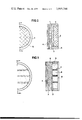
- FIGS. 2 and 3 represent a schematic section of two possible embodiments of a bipolar electrode for a battery according to the present invention
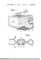
- FIG. 4 shows a partial perspective view of a battery according to the present invention
- FIG. 5 shows a cross-sectional view of a filter for the battery illustrated in FIG. 4;
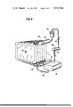
- FIG. 6 shows a perspective view of another embodiment of a battery according to the present invention.
- FIG. 7 represents the voltage/time curves of three active cathodic substances for a battery according to the present invention.
- the bipolar electrode of the present invention is constituted by an impermeable electrically conducting membrane 1, bonded by a thin layer of graphite cement 2 to a layer of porous graphite felt 3. On the other side of the membrane is a layer 4 of zinc deposited to form an anode. Retaining means for the graphite cement and the porous graphite felt is shown at 5.
- a thin metal sheet 6 may be used as a membrane rather than graphite fibers.
- the metal sheet is conductive and is coated on either side with a layer 2 of graphite cement.
- short sticks of electrographite 7 may be gluded onto the graphite covered metal sheet to form grooves or channels 8 which hold an active cathodic mass made of paste.
- a retaining ring 5 and a porous, insulating partition 9 holds the active cathodic mass in place.
- an impermeable sheet of moulded graphite resin (10) may be used to replace the membrane 1 or the graphite covered sheet 6 of FIGS. 2 and 3, respectively.
- the bipolar electrode is fitted into a chassis 12 of which it constitutes one of the side walls.
- the wall of the opposite side remains open, being covered, during assembly, by the bipolar electrode of the neighboring cell.
- the electrolytic zone 13 is defined between two neighboring bipolar electrodes and is bounded by a part of the chassis 12.
- thin reinforcement elements 14 may be placed within the electrolytic zone 13.
- the electrolyte leaves the electrolytic zone 13 through a series of holes, 11 and 16, which traverse the upper and lower walls respectively of the chassis 12, the holes leading from and to collecting pipes 22, 23 respectively.
- the cells 15 are arranged in series.
- the first cell of the battery is closed by a conductive wall on which the layer 4 of zinc is deposited and which is in electrical connection with the negative terminal 27 of the battery.
- each of the pipes 23 which carry the electrolyte away from the cells is connected to the top of the tank 19 by individual conduits 17.
- a single pump 20 serves to draw the electrolyte out of the tank 19 and to supply it via a discharge conduit 18 and a distributing channel 31 to the pipes 22 from whence it is fed into the cells.
- a filter 21 is inserted between the channel 31 and each of the pipes 22 which eliminates any solid particles which may have entered the electrolyte and causes a break in the electrical conductivity of the flow of the electrolyte and prevents the cells 15 from being short circuited.
- the filter 21 is constituted by a holder 25 into which porous diaphragms 24 are inserted; the diaphragms 24 increase the electrical resistance of the jet of electrolyte by a factor of about 5.
- each cell 15 is linked to a small bore tube 28 which collects any gas which may have formed to diminish the risk of a lack of uniformity in the deposit of zinc.
- the gas is removed by means of a small, intermittently operating, pneumatic pump.
- the electrolyte is circulated by a single pneumatic pump 29.
- the upper pipes 23 lead into a tube 30 which, in turn, leads to an overflow tank 32.
- the pipes 22 lead to the channel 31 which is linked via the conduit 18 with the tank 19.
- the pneumatic pump 29 works by alternately sucking and pumping (with a cycle of between 1 and 5 minutes) the electrolyte in the tank 19 via a channel 34 so that the electrolyte is forced into the zones 13 of the cells 15 and then withdrawn therefrom.
- the pump 29 sucks electrolyte from the overflow tank 32 via a channel 33.
- there is no need to provide pipes to extract gas bubbles formed in the electrolyte since the pump 29 will also withdraw any bubbles of gas that may have formed in the cells 15.
- the battery according to the present invention comprises a plurality of cells 15 arranged in series (cf. FIGS. 4 and 6). Each cell contains a bipolar electrode which defines one wall of a zone 13 for electrolyte (FIG. 1), the opposite wall (not shown) being defined by the bipolar electrode of the adjacent cell.
- the layer of porous graphite felt is impregnated with at least one active cathodic substance which is such as to form solid addition products with the free bromine in the cell;
- the active cathodic substances listed below, may be used separately or in combination:
- TMACIO. tetramethylammonium perchlorate
- FIG. 7 shows the discharge curve of a cell containing TMA- ClO, and that of a cell containing ExhBr.
- the latter retains more moles of free bromine which gives the cell or the battery a greater specific capacity but the restitution rate is slower and this results in the descending discharge curve.
- TMClO however, has a more linear curve but its specific capacity is less as it becomes discharged more rapidly.
- FIG. 7 also prevents the curve obtained by mixing the two substances, and it will be seen that this curve lies between that of the TMACIO, and that of the ExhBr.
- one or the other of these active cathodic substances or a mixture of the two in appropriate proportions may be chosen. According to the active cathodic substance chosen, the discharging characteristics of a given cell will be different in accordance with the type of battery desired.
- the impregnation of the layer 3 with the chosen active cathodic substance is carried out by a process of exchange with a salt soluble in water.
- a process of exchange with a salt soluble in water For example, when TMAClO is used the process is as follows:
- TMABr tetramethylammonium bromide
- the impermeable conducting membrane 1 may preferably be constructed of graphite fibers, examples of which are tabulated below:
- graphite felt 3 of FIG. 2 short sticks of electrographite (see FIG. 3) may be glued onto the graphite covered metal sheet with graphite cement to form grooves or channels 8 in which may be placed an active cathodic mass made of paste comprising, for example, graphite powder, an active cathodic substance (TMAClO and an inert powder of porous carbon.
- an active cathodic mass made of paste comprising, for example, graphite powder, an active cathodic substance (TMAClO and an inert powder of porous carbon.
- a retaining ring 5, preferably made of plastics material, and a porous, insulating partition 9 holds in place the active cathodic mass which could or might otherwise escape.
- an impermeable sheet or plate of moulded graphite resin (FIG. 1) may be used.
- the graphite resin employed may be that sold under the Trade Mark SIGRADUR N6, the characteristics of which are given in the foregoing Table.
- the sheets of moulded graphite resin 10 are smooth on one side to receive the layer 4 of zinc while the other side is furnished with diaphragms which form channels 8; these channels 8 are produced by a moulding process.
- the graphite resin may be smooth on both sides and have a layer of porous graphite felt, similar to the layer 3, on one side and the layer 4 of zinc on the other.
- the bipolar electrode of the present invention will always be of a sandwich construction, one layer of which will always be constituted by a layer of zinc that is deposited during a charging process.
- the deposit of zinc is extremely thin having a thickness of a few hundredths of a millimeter, for example between 3/100 and 10/100 mm and preferably about 7/100 mm. Such a thickness precludes the formation of dendritic deposits. In the present invention this is obtained by carrying out the charging and discharging processes under conditions of a slight insufficiency of zinc.
- the desired thickness is obtained, within the cells of the battery of the present invention, by the fact that the capacity of the battery itself is limited by the bromine cathode to 3-5 ah/dm (amp hours per square decimeter).
- the quantity of zinc that is deposited may be established as follows: (electrochemical equivalent of zinc) X (the maximum number of Ah/dm efficiency. The efficiency being about this calculation gives the figure of about 5 grams of zinc. This quantity of zinc corresponds to about 0.7 cm of zinc distributed over an area of 1 dm with a thickness of about 7/100 mm.
- the bipolar electrode hereinbefore described is fitted into a chassis 12 (see FIG. 1) of which it constitutes one of the side walls, while the wall of the opposite side remains open, being covered, during assembly, by the bipolar electrode of the neighboring cell.
- the zone 13 is defined between two neighboring bipolar electrodes and is bounded by a part of the chassis 12.
- thin reinforcement elements 14 preferably made of plastics material, may be placed within the zone 13.
- the electrolyte enters and leaves the zone 13 through a series of holes ll, 16 which traverse the upper and lower walls respectively of the chassis 12 (as seen in FIG. 1), the holes leading from and to collecting pipes 22, 23 respectively. It matters little whether the electrolyte circulates upwardly or downwardly through the cell or alternately in each direction.
- the electrolyte is formed of an aqueous solution of zinc bromide with a weight ratio of water to bromine of about :100.
- BROMIC ACID HBr
- Bromic acid is added to increase the conductivity and acidity (pH between 0 and l) in order to avoid the formation of zinc hydroxide which would otherwise cause the solution to turn cloudy and eventually form an un desirable precipitate.
- the bromic acid is also intended to compensate for the loss of free bromine due to the small amount of free bromine which is retained by all the inactive parts of the battery (i.e. the chassis 12, the retaining ring 5, the partition 9 and the pipes 22, 23 etc.).
- bromic acid causes a slight reduction in the charge efficiency; this in turn means that there is a slight insufficiency of zinc compared with that determined by the stoichiometric conditions of working, and promotes an even deposit of zinc as mentioned above.
- a DUAL PURPOSE SALT The dual purpose salt serves to maintain the conductivity of the electrolyte at an adequate level when, towards the end of the charging process, almost allthe zinc bromide has disappeared, and tomaintain in solution ions which prevent free bromine from dissolving in water.
- a salt which fulfils those purposeswell is sodium sulphate, its 80. ions are very good at preventing free bromine from dissolving in water.
- AN ADDITIONAL SALT The solubility of the active cathodic substance used to create solid addition products with the cathodic bromine is already low but it may be reduced still further by adding an additional salt. This additional salt may also function to maintain the conductivity of the'electrolyte at an adequate leveltowards the end of the charging process, thus reinforcing the effect of the dual purpose salt.
- TMAClO a salt which fulfils this purpose very well is sodium perchlorate (NaClO
- NaClO sodium perchlorate
- the cells as mentioned before are arranged in series (see FIG. 4).
- the first cell of the battery is closed by a conductive wall on which the layer 4 of zinc is deposited and which is in electrical connection with the negative terminal 27 of the battery.
- the last cell has an electrode which serves as a unipolar cathode and is electrically connected to 'the positive terminal (not shown) of the battery.
- Each of the pipes 23, which carry the electrolyte away from the cells, is connected to the top of the tank 19 by individual conduits 17. By this means no one particular cell can come into electrical contact with a neighboring cell or cells via the electrolyte as the electrical conductivity is broken by the jet of electrolyte falling into the tank 19.
- a single pump 20 serves to draw the electrolyte out of the tank 19 and to supply it via a discharge conduit 18 and a distributing channel 31 to the pipes 22 from whence it is fed into the cells.
- a filter 21 which serves two purposes: first, it eliminates any solid particles which may have entered the electrolyte; and second, it causes a break in the electrical conductivity of the flow of the electrolyte and prevents the cells 15 from being short circuited.
- the filter 21 is constituted by a holder into which porous diaphragms 24 are inserted; the diaphragms 24 increase the electrical resistance of the jet of electrolyte by about five times.
- bubbles of gas are liable to form and cling to the surface of the layer 4 of zinc and to the partition 9.
- Such bubbles have an adverse influence as they make it more difficult for the electrolyte to reach all the active cathodic material and cause a lack of uniformity in the deposit of zinc.
- the top of each cell 15 is linked to a small bore tube 28 which collects any gas which may have formed. This gas is removed by means of a small intermittently operating pneumatic pump 26 (see FIGS. 1 and 4).
- the electrolyte is circulated by a single pneumatic pump 29.
- the upper pipes 23 lead into a tube 30 which, in turn, leads to an overflow tank 32.
- the pipes 22 lead to the channel 31 which is linked, via the conduit 18, with the tank 19.
- the pneumatic pump 29 works by alternately sucking and pumping (with a cycle of between i and 5 minutes) the electrolyte in the tank 19 via a channel 34 so that the electrolyte is forced into the zones 13 of the cells 15 and then withdrawn therefrom.
- the pump 29 sucks electrolyte from the overflow tank 32 via a channel 33.
- the advantage of this embodiment lies in the fact that there is no need to provide pipes 28 to extract gas bubbles formed in the electrolyte since the pump 29 will also withdraw any bubbles of gas that may have formed in the cells 15.
- the percentage of free bromine in the electrolyte is very low (less than 0.2%) which means that high charge efficiency can be obtained.
- An electric battery comprising a plurality of cells arranged in series, each cell comprising a bipolar electrode between neighboring cells, said bipolar electrode having deposited on one side a zinc anode and on the other side a bromine cathode including an active cathodic mass, said active cathodic mass containing an active cathodic substance, said active cathodic substance being substantially insoluble in water and capable of combining with cathodic bromine to form solid addition products and selected from the group consisting of tetramethylammonium perchlorates, tetraethylammonium perchlorates, tetrabutylammonium perchloroates, phenyltrimethylammonium perchlorates, phenyltrimethylammonium bromides, cetyltrimethylammonium perchlorates, cetyltrimethylammonium bromides, hexamethonium perchlorates, hexamethonium bromides, decamethonium perchlor
- the filter means comprises a plurality of filters, each of said filters having a filter holder having at least one porous diaphragm arranged to increase the electrical resistance to the flow of the electrolyte.
- the electric battery of claim 3 wherein the pump is a pneumatic pump which communicates with a storing means for storing electrolyte when the battery is not in use.
Landscapes
- Engineering & Computer Science (AREA)
- Manufacturing & Machinery (AREA)
- Chemical & Material Sciences (AREA)
- Chemical Kinetics & Catalysis (AREA)
- Electrochemistry (AREA)
- General Chemical & Material Sciences (AREA)
- Hybrid Cells (AREA)
Abstract
An electric battery is disclosed comprising a plurality of cells arranged in series, each cell comprising an aqueous electrolyte of zinc bromide circulated through the cells during charging and discharging, a bipolar electrode having a zinc anode deposited on one side and a bromine cathode and active cathodic mass on the other side. The active cathodic mass contains an active cathodic substance which is substantially insoluble in water and which is capable of combining with cathodic bromine to form solid addition products. Additive substances are dissolved in the electrolyte to reduce the solubility of the active cathodic substance, to increase the conductivity and acidity of the electrolyte, and to encourage the zinc to deposit in a thin and uniform layer.
Description
mted States Patent 1191 1111 3,915,744
DeRossi 5] Oct. 28, 1975 1 ELECTRIC BATTERY 3,382,102 5/1968 ZitO, Jr. 136/30 [75] Inventor: Mario DeRossi, Rome, Italy 73] A i c i li Nazionaue n Rica-Che 3,728,158 4/1973 Poe et al..., 136/10 Rome, Italy P E J h H M k rtmary xammer o n ac [22] Flledi 1974 Assistant ExaminerC. F. Lefevour [21] A N 430,411 Attorney, Agent, or FirmD. Paul Weaver Related US. Application Data [62] Division of Ser. No. 283,488, Aug. 24, 1972, Pat. No. [57] ABSTRACT 3,3 1 945, An electric battery is disclosed comprising a plurality of cells arranged in series, each cell comprising an [30] Foreign Application Priority Data aqueous electrolyte of zinc bromide circulated Aug. 31, 1971 Switzerland 12758/71 through the cells during Charging and discharging a bipolar electrode having a zinc anode deposited on 52 us. or. 136/10; 136/30; 136/100; One side and a bmmine Cathode and active 136/1 5 5 mass on the other side. The active cathodic mass con- [51] Int. Cl. H01M 39/06 wins an active cathodic substance which is Substan' [58] Field Of Search 136/10-12, tially insoluble in Water and which is Capable of 13 100 30 2 55 bining With cathodic bromine to form SOiid addition products. Additive substances are dissolved in the [56] References Cited electrolyte to reduce the solubility of the active ca- UNITED STATES PATENTS thodic substance, to increase the conductivity and acidity of the electrolyte, and to encourage the zinc to 1,499,907 7/1924 Brown 136/10 X deposit i a thin and uniform layer. 3,167,456 1/1965 Schilke et a1. 136/10 3,359,136 12/1967 Merten et a1. 136/30 5 Claims, 7 Drawing Figures US. Patent Oct. 28, 1975 Sheet 2 of5 3,915,744
US. Patent Oct. 28, 1975 Sheet 3 of5 3,915,744
U.S. Patent Oct. 28, 1975 Sheet4 0f5 3,915,744
FIG 6 US. Patent Oct. 28, 1975 Sheet 5 of5 3,915,744
fig 7 Vol! TMA ClO Exh Br l l l I ELECTRIC BATTERY PRIOR RELATED APPLICATION This is a division of application Ser. No. 283,488, filed Aug. 24, 1972 now U.S. Pat. No. 3,811,945.
BACKGROUND OF THE INVENTION This invention relates to electric batteries.
A battery is known which has a zinc electrode and a bromine electrode between which is an aqueous electrolyte of zinc bromide.
This type of battery has a high theoretic specific energy (i.e. high energy per unit mass). The battery may, therefore, have a specific energy of more than 430 Wh/kg (Wh/kg watt hours per kilogram) and will produce an e.m.f. of about 1.80 volts per cell.
The working of such a battery takes place according to the following electrochemical reactions:
at the anode Zn Zn 2e at the cathode Br 2c 2Br' the circuit being completed within the cell by two electrodes made of conductive material which do not participate in the electrochemical reaction. During the charging process a deposit of zinc is formed at the anode and there is a discharge of free bromine at the cathode.
During the discharge process zinc dissolves in the electrolyte, the free bromine which had accumulated at the cathode is ionized and, as a result, the aqueous electrolyte is enriched with a concentration of zinc bromide.
The above account describes the working of the battery in theory. In practice, there are two important drawbacks which may be summed up as follows:
A. BROMINE CATHODE Bromine is not very soluble in water (about 3%) but I the presence of zinc bromide in the electrolyte causes the solubility of the bromine to rise to about 50%. I
A zinc anode reacts very quickly with an electrolyte containing a high percentage of bromine and is liable to cause auto-discharge of the cell and very low charge efficiency.
During the charging process the quantity of free bromine formed in the cell has, therefore, to be controlled very closely to prevent it from dissolving in the electrolyte.
The free bromine which is formed during the charging process has, therefore, to be captured and then released during the discharging process with a high restitution rate.
B. ZINC ANODE Density gradients in the electrolyte cause a lack of uniformity in the deposit of the zinc on the anode (especially if this deposit is rather thick) and zinc dendrites soon appear, bringing about an internal shortcircuit of the cells and thereby of the battery as a whole.
Several solutions to these drawbacks have been previously proposed.
In U.S. Pat. No. 3,382,102 there is a proposal to retain the free bromine by pulverulent active carbon contained in grooves made in a porous plate, made of carbon or graphite. However, carbon has a very low capacity for absorbing free bromine (about 1:1 by weight) and the restitution rate is also very slow. Furthermore, during the charging process, density gradients are formed both at the cathode and in the electrolyte. There results a lack of uniformity in the deposit of the zinc and rapid corrosion in the area where the free bromine is most concentrated.
U.S. Pat. No. 3,285,781 seeks to eliminate these density gradients in a battery having a zinc anode and a bromine cathode by placing horizontal insulating diaphragms between a carbon cathode and a zinc anode. But this does not prevent some free bromine from forming in the electrolyte during the charging process and this causes the battery to discharge itself.
British Pat. Specification No. 320,916 and U.S. Patent No. 3,328,202 suggest the use of powdered carbon to retain the free bromine. This results in the same drawbacks as have already been mentioned above.
The present applicant has proposed in his British Pat. Specification No. 1,234,414 the use of organic solvents (such as CHBr CCl CS etc.) in place of carbon to retain the free bromine. Although this solution is technically valid it causes the weight of the battery to be increased. I
A better solution is proposed in U.S. Pat. No. 2,566,114 where it is suggested that alkylammonium halide, for example tetramethylammonium bromide (hereinafter referred to as TMABr) be added to the powdered carbon surrounding the cathode. TMABr serves to form reversible addition products with the free bromine by retaining it in high proportions (moles of free bromine: moles of TMABr 4:1 or more).
The drawback inherent'in this solution is that not all of the intermediate addition products which are formed between the bromine and the alkylammonium halides during the charging process are in a solid state and this results in'addition products rich in bromine flowing along the cathode thus causing a lack of uniformity in the capacity of the cathode. Another drawback is that the electrolyte contains free bromine and there ensues a more or less rapid auto-discharge of the battery and corrosion of the zinc anode. The problem of density gradients in the electrolyte also remains unsolved.
Alkylammonium halides are generally very soluble in water, and are partially ionised in the aqueous electrolyte. In the cae of bromine the first addition product formed with the alkylammonium halide during the charging process is produced mainly on the surface of the cathode and prevents it from absorbing further quantities of free bromine.
On the other hand, experiments have shown that each mole of alkylammonium halide is capable of absorbing-several moles of free bromine with reactions of the following type:
(TMA+'+ Br Br TMA+ Br TMABr solidi (TMA+ Br 313:, TMA Br; TMABr solidi With TMABr solid TMABr is formed first, then liquid eutectic mixtures and then, finally, solid TMABr Thus, during the charging and discharging processes, the addition products are liquid for a time and flow down the cathode; the distribution of the capacity of the cathode and anode is, therefore, not uniform.
n As a result, the discharge potentials are different, and during both the charging and discharging processes, the e.m.f. increases or decreases in steps.
The present applicant proposes in his British Pat. Specification No. 1,237,964 the use of tetralkylammonium perchlorate in the form of a paste in contact The with the cathode. The use of tetramethylammonium perchlorate (herein referred to as TMACIO instead of alkylammonium halide has two great advantages. Firstly, once the TMACIO, has been introduced into the cathode, it hardly dissolves in the electrolyte whilst adding perchlorates, for example sodium perchlorate, to the electrolyte makes the TMACIO, even less soluble. As a result, the addition product which is formed with the free bromine during the charging process is evenly distributed within the interior of the cathode and not only on the surface. The second advantage lies in the fact that as TMAClO causes the formation of only one solid additive, TMABr and avoids the steps in the e.m.f. which are characteristic when using alkylammonium halide.
Other substances as well as alkylammonium halides are capable of forming additional products with free bromine (see U.S. Pat. No. 3,057,760) but they require special means to put them into practice.
The present invention seeks to provide a battery without the aforementioned disadvantages.
SUMMARY OF THE INVENTION The present invention is directed toward a battery including a plurality of cells arranged in series, each cell comprising: a bipolar electrode which serves to separate neighboring cells; an aqueous electrolyte of zinc bromide which is continuously circulated through the cells during the charging and discharging processes, and stored in an autonomous tank when the battery is not in use; the bipolar electrode having deposited on one side a zinc anode and on the other side a bromine cathode including an active cathodic mass, the active cathodic mass containing an active cathodic substance which is substantially insoluble in water and which is capable of combining with cathodic bromine to form solid addition products, the active cathodic substance being selected from at least one of the group comprising alkylammonium perchlorate, diamine bromides, diamine perchlorates, triamine bromides and triamine perchlorates, additive substances being dissolved in the electrolyte to reduce the solubility of the active cathodic substance, to increase the conductivity and the acidity of the electrolyte and to encourage the zinc to deposit in a thin and uniform layer.
BRIEF DESCRIPTION OF THE DRAWINGS The invention is illustrated, merely by way of example, in the accompanying drawings, in which:
FIG. 1 shows a perspective view, partially cut-away, of a cell of a battery according to the present invention;
FIGS. 2 and 3 represent a schematic section of two possible embodiments of a bipolar electrode for a battery according to the present invention;
FIG. 4 shows a partial perspective view of a battery according to the present invention;
FIG. 5 shows a cross-sectional view of a filter for the battery illustrated in FIG. 4;
FIG. 6 shows a perspective view of another embodiment of a battery according to the present invention; and
FIG. 7 represents the voltage/time curves of three active cathodic substances for a battery according to the present invention.
In the drawings like parts have been given the same reference numerals throughout.
Referring to the drawings, in toto, the parts will be listed and described briefly. Their interrelated functions will be described in more detail in the preferred embodiments. In the drawings like parts have been given the same reference numerals throughout the figures.
Referring to FIG. 2, it will be seen that the bipolar electrode of the present invention is constituted by an impermeable electrically conducting membrane 1, bonded by a thin layer of graphite cement 2 to a layer of porous graphite felt 3. On the other side of the membrane is a layer 4 of zinc deposited to form an anode. Retaining means for the graphite cement and the porous graphite felt is shown at 5.
Referring to FIG. 3, a thin metal sheet 6 may be used as a membrane rather than graphite fibers. The metal sheet is conductive and is coated on either side with a layer 2 of graphite cement. Instead of the graphite felt 3 of FIG. 2, short sticks of electrographite 7 may be gluded onto the graphite covered metal sheet to form grooves or channels 8 which hold an active cathodic mass made of paste. A retaining ring 5 and a porous, insulating partition 9 holds the active cathodic mass in place.
Referring to FIG. 1, an impermeable sheet of moulded graphite resin (10) may be used to replace the membrane 1 or the graphite covered sheet 6 of FIGS. 2 and 3, respectively. The bipolar electrode is fitted into a chassis 12 of which it constitutes one of the side walls. The wall of the opposite side remains open, being covered, during assembly, by the bipolar electrode of the neighboring cell. Thus, the electrolytic zone 13 is defined between two neighboring bipolar electrodes and is bounded by a part of the chassis 12. In large cells thin reinforcement elements 14 may be placed within the electrolytic zone 13.
The electrolyte leaves the electrolytic zone 13 through a series of holes, 11 and 16, which traverse the upper and lower walls respectively of the chassis 12, the holes leading from and to collecting pipes 22, 23 respectively.
The cells 15 are arranged in series. The first cell of the battery is closed by a conductive wall on which the layer 4 of zinc is deposited and which is in electrical connection with the negative terminal 27 of the battery.
Referring to FIG. 4, each of the pipes 23 which carry the electrolyte away from the cells is connected to the top of the tank 19 by individual conduits 17. A single pump 20 serves to draw the electrolyte out of the tank 19 and to supply it via a discharge conduit 18 and a distributing channel 31 to the pipes 22 from whence it is fed into the cells. A filter 21 is inserted between the channel 31 and each of the pipes 22 which eliminates any solid particles which may have entered the electrolyte and causes a break in the electrical conductivity of the flow of the electrolyte and prevents the cells 15 from being short circuited.
Referring to FIG. 5, the filter 21 is constituted by a holder 25 into which porous diaphragms 24 are inserted; the diaphragms 24 increase the electrical resistance of the jet of electrolyte by a factor of about 5.
Referring to FIG. 4, the top of each cell 15 is linked to a small bore tube 28 which collects any gas which may have formed to diminish the risk of a lack of uniformity in the deposit of zinc. The gas is removed by means of a small, intermittently operating, pneumatic pump.
In another embodiment of a battery according to the present invention and shown in FIG. 6, the electrolyte is circulated by a single pneumatic pump 29. The upper pipes 23 lead into a tube 30 which, in turn, leads to an overflow tank 32. The pipes 22 lead to the channel 31 which is linked via the conduit 18 with the tank 19. The pneumatic pump 29 works by alternately sucking and pumping (with a cycle of between 1 and 5 minutes) the electrolyte in the tank 19 via a channel 34 so that the electrolyte is forced into the zones 13 of the cells 15 and then withdrawn therefrom. The pump 29 sucks electrolyte from the overflow tank 32 via a channel 33. In this embodiment there is no need to provide pipes to extract gas bubbles formed in the electrolyte, since the pump 29 will also withdraw any bubbles of gas that may have formed in the cells 15.
DESCRIPTION OF THE PREFERRED EMBODIMENTS The battery according to the present invention comprises a plurality of cells 15 arranged in series (cf. FIGS. 4 and 6). Each cell contains a bipolar electrode which defines one wall of a zone 13 for electrolyte (FIG. 1), the opposite wall (not shown) being defined by the bipolar electrode of the adjacent cell.
Referring to FIG. 2, the layer of porous graphite felt is impregnated with at least one active cathodic substance which is such as to form solid addition products with the free bromine in the cell; the active cathodic substances, listed below, may be used separately or in combination:
tetramethylammonium perchlorate (TMACIO.,)
tetraethylammonium perchlorate tetrabutylammonium perchlorate phenyltrimethylammonium perchlorate and/or bromide cetyltrimethylammonium perchlorate and/or bromide hexamethonium perchlorate and/or bromide decamethonium perchlorate and/or bromide and in accordance with the theoretical basis of the present invention, none of these substances dissolves easily in water (for example, TMACIO has a solubility of 0.4 grams in l00 grams of water), and all form addition products with bromine.
The above-mentioned active cathodic substances have been examined according to the following criteriaz a. to check whether the active cathodic substance gives a solid addition product with bromine;
b. to establish the number of moles of free bromine retained by each mole of the active cathodic substance; and
c. to check the restitution rate at the bromine cathode, that is to say whether the free bromine is more or less easily liberated by the active cathodic substance.
According to the present invention, it has been established that, from the point of view of criteria (a) and (b), the best results were obtained with TMAClO and hexamethonium bromide (herein referred to as ExhBr). These form solid addition products, and retain high quantities of moles of free bromine but from the point of view of criteria (0) are very different, as may be seen from their discharge curves in a cell having a bromine cathode.
This will be immediately apparent from FIG. 7 which shows the discharge curve of a cell containing TMA- ClO, and that of a cell containing ExhBr. The latter retains more moles of free bromine which gives the cell or the battery a greater specific capacity but the restitution rate is slower and this results in the descending discharge curve.
TMClO however, has a more linear curve but its specific capacity is less as it becomes discharged more rapidly.
FIG. 7 also prevents the curve obtained by mixing the two substances, and it will be seen that this curve lies between that of the TMACIO, and that of the ExhBr.
Depending on the use to which the battery is to be put, one or the other of these active cathodic substances or a mixture of the two in appropriate proportions may be chosen. According to the active cathodic substance chosen, the discharging characteristics of a given cell will be different in accordance with the type of battery desired.
The impregnation of the layer 3 with the chosen active cathodic substance is carried out by a process of exchange with a salt soluble in water. For example, when TMAClO is used the process is as follows:
A solution of an alkylammonium halide, e.g., tetramethylammonium bromide, hereinafter referred to as TMABr, which is easily dissolved in water, is made up and the layer 3 is impregnated with the solution; the TMACIO is then precipitated by adding a water soluble perchlorate (e.g., sodium perchlorate) according to the following reaction:
TMABr NaClO TMACIO, NaBr after which the sodium bromide, which is very soluble in water, is removed by washing, leaving the layer 3 impregnated with a uniform dispersion of the relatively insoluble TMACIO The impermeable conducting membrane 1 may preferably be constructed of graphite fibers, examples of which are tabulated below:
TABLE Type of Graphite and Commercial Name Specific Weight in gr/cm Weight of Electrode in dmlg Thickness of Electrode (mm) Resistance In mm /m 1 impermeable membrane 1 SlGRAFLEX (Trade Mark) 2 Layer 3 of SIGRATHERM (Trade Mark) (Trade Mark) TABLE- Continued Type of Graphite Specific Weight of Thickness and Commercial Weight in Resistance Electrode of Electrode No. Name gr/cm ln mmlm in dmlg (mm) 4 Electrogruphite ELECTROCAR- BONIUM 470 (Trade Mark) 1.8 10 70-140 4-8 Instead of the membrane being of graphite fibres which is technically excellent but costly a thin metal sheet 6 may be used (see FIG. 3). The sheet should be conductive and may be made of iron coated on either side with a layer 2 of graphite cement (composed of graphite and resin) which has been cured or coked so as to achieve a graphite covered metal sheet.
On one side of the graphite covered metal sheet is applied a layer of porous graphite felt impregnated as hereinbefore described with reference to FIG. 2, whilst the other side is ready to receive the layer 4 of zinc.
Instead of the graphite felt 3 of FIG. 2 short sticks of electrographite (see FIG. 3) may be glued onto the graphite covered metal sheet with graphite cement to form grooves or channels 8 in which may be placed an active cathodic mass made of paste comprising, for example, graphite powder, an active cathodic substance (TMAClO and an inert powder of porous carbon. A retaining ring 5, preferably made of plastics material, and a porous, insulating partition 9 holds in place the active cathodic mass which could or might otherwise escape.
The respective quantities of the constituents of the active cathodic mass are not critical. However, it has been established by experiment that the optimum values vary according to the use to which the battery is to be put. The following ratios are given by way of example:
a. graphite paste Active cathodic substance porous carbon 3 3 5 (ratio by weight) b. graphite paste active cathodic substance porous carbon =1 1 1 (ratio by weight) The weight of the bipolar electrode shown in FIG. 3 is greater than that of the bipolar electrode shown in FIG. 2 but it is much less expensive to manufacture. Technically, the solutions are equally valid so that the choice between the two will be dictated by criteria of price and weight according to the application to which the battery is to be put.
In place of the membrane 1 (see FIG. 2) or the graphite covered sheet 6 (see FIG. 3) an impermeable sheet or plate of moulded graphite resin (FIG. 1) may be used. The graphite resin employed may be that sold under the Trade Mark SIGRADUR N6, the characteristics of which are given in the foregoing Table. In the embodiment illustrated in FIG. 1, the sheets of moulded graphite resin 10 are smooth on one side to receive the layer 4 of zinc while the other side is furnished with diaphragms which form channels 8; these channels 8 are produced by a moulding process. Of course, the graphite resin may be smooth on both sides and have a layer of porous graphite felt, similar to the layer 3, on one side and the layer 4 of zinc on the other.
The bipolar electrode of the present invention will always be of a sandwich construction, one layer of which will always be constituted by a layer of zinc that is deposited during a charging process. According to the present invention, the deposit of zinc is extremely thin having a thickness of a few hundredths of a millimeter, for example between 3/100 and 10/100 mm and preferably about 7/100 mm. Such a thickness precludes the formation of dendritic deposits. In the present invention this is obtained by carrying out the charging and discharging processes under conditions of a slight insufficiency of zinc. The desired thickness is obtained, within the cells of the battery of the present invention, by the fact that the capacity of the battery itself is limited by the bromine cathode to 3-5 ah/dm (amp hours per square decimeter). The quantity of zinc that is deposited may be established as follows: (electrochemical equivalent of zinc) X (the maximum number of Ah/dm efficiency. The efficiency being about this calculation gives the figure of about 5 grams of zinc. This quantity of zinc corresponds to about 0.7 cm of zinc distributed over an area of 1 dm with a thickness of about 7/100 mm.
Furthermore, the formation of zinc dendrites is avoided as the surface on which the zinc is deposited is perfectly smooth, being free of the irregularities customarily found in conventional zinc batteries.
The bipolar electrode hereinbefore described is fitted into a chassis 12 (see FIG. 1) of which it constitutes one of the side walls, while the wall of the opposite side remains open, being covered, during assembly, by the bipolar electrode of the neighboring cell. Thus, the zone 13 is defined between two neighboring bipolar electrodes and is bounded by a part of the chassis 12.
In large-sized cells thin reinforcement elements 14, preferably made of plastics material, may be placed within the zone 13.
The electrolyte enters and leaves the zone 13 through a series of holes ll, 16 which traverse the upper and lower walls respectively of the chassis 12 (as seen in FIG. 1), the holes leading from and to collecting pipes 22, 23 respectively. It matters little whether the electrolyte circulates upwardly or downwardly through the cell or alternately in each direction.
The electrolyte is formed of an aqueous solution of zinc bromide with a weight ratio of water to bromine of about :100.
To the aqueous solution of zinc bromide is added: 1. BROMIC ACID (HBr) Bromic acid is added to increase the conductivity and acidity (pH between 0 and l) in order to avoid the formation of zinc hydroxide which would otherwise cause the solution to turn cloudy and eventually form an un desirable precipitate. The bromic acid is also intended to compensate for the loss of free bromine due to the small amount of free bromine which is retained by all the inactive parts of the battery (i.e. the chassis 12, the retaining ring 5, the partition 9 and the pipes 22, 23 etc.).
The presence of the bromic acid causes a slight reduction in the charge efficiency; this in turn means that there is a slight insufficiency of zinc compared with that determined by the stoichiometric conditions of working, and promotes an even deposit of zinc as mentioned above.
2. A DUAL PURPOSE SALT The dual purpose salt serves to maintain the conductivity of the electrolyte at an adequate level when, towards the end of the charging process, almost allthe zinc bromide has disappeared, and tomaintain in solution ions which prevent free bromine from dissolving in water. A salt which fulfils those purposeswell is sodium sulphate, its 80. ions are very good at preventing free bromine from dissolving in water.
3. AN ADDITIONAL SALT The solubility of the active cathodic substance used to create solid addition products with the cathodic bromine is already low but it may be reduced still further by adding an additional salt. This additional salt may also function to maintain the conductivity of the'electrolyte at an adequate leveltowards the end of the charging process, thus reinforcing the effect of the dual purpose salt. When the active cathodic substance is TMAClO a salt which fulfils this purpose very well is sodium perchlorate (NaClO A preferred composition for the electrolyte is given below:
Water 100 pans by weight zinc bromide 100 parts by weight brornic acid 3 pans by weight sodium sulphate sodium perchlorate total electrolyte:
7 pans by weight l4 parts by weight 224 parts by weight of inactivity the electrolyte is stored in a separate tank- 19 (see FIGS. 4 and 6).
The cells as mentioned before are arranged in series (see FIG. 4). The first cell of the battery is closed by a conductive wall on which the layer 4 of zinc is deposited and which is in electrical connection with the negative terminal 27 of the battery.
This first cell and its immediate neighbor are hermetically separated by the bipolar electrode; the same applies to each pair of adjacent cells. The last cell has an electrode which serves as a unipolar cathode and is electrically connected to 'the positive terminal (not shown) of the battery.
Each of the pipes 23, which carry the electrolyte away from the cells, is connected to the top of the tank 19 by individual conduits 17. By this means no one particular cell can come into electrical contact with a neighboring cell or cells via the electrolyte as the electrical conductivity is broken by the jet of electrolyte falling into the tank 19.
A single pump 20 serves to draw the electrolyte out of the tank 19 and to supply it via a discharge conduit 18 and a distributing channel 31 to the pipes 22 from whence it is fed into the cells.
Between the channel 31 and each of the pipes 22 is inserted a filter 21 which serves two purposes: first, it eliminates any solid particles which may have entered the electrolyte; and second, it causes a break in the electrical conductivity of the flow of the electrolyte and prevents the cells 15 from being short circuited.
In the embodiment illustrated in FIG. 5, the filter 21 is constituted by a holder into which porous diaphragms 24 are inserted; the diaphragms 24 increase the electrical resistance of the jet of electrolyte by about five times.
It will be appreciated that similar filters may be placed at the exit of the pipes 23 which could then be connected to a single conduit leading to the tank 19.
During the charging and discharging processes bubbles of gas (especially bubbles of hydrogen) are liable to form and cling to the surface of the layer 4 of zinc and to the partition 9. Such bubbles have an adverse influence as they make it more difficult for the electrolyte to reach all the active cathodic material and cause a lack of uniformity in the deposit of zinc. To diminish the risk of this occurring, the top of each cell 15 is linked to a small bore tube 28 which collects any gas which may have formed. This gas is removed by means of a small intermittently operating pneumatic pump 26 (see FIGS. 1 and 4).
In another embodiment of a battery according to the present invention and shown in FIG. 6, the electrolyte is circulated by a single pneumatic pump 29. The upper pipes 23 lead into a tube 30 which, in turn, leads to an overflow tank 32. The pipes 22 lead to the channel 31 which is linked, via the conduit 18, with the tank 19. The pneumatic pump 29 works by alternately sucking and pumping (with a cycle of between i and 5 minutes) the electrolyte in the tank 19 via a channel 34 so that the electrolyte is forced into the zones 13 of the cells 15 and then withdrawn therefrom. The pump 29 sucks electrolyte from the overflow tank 32 via a channel 33.
The advantage of this embodiment lies in the fact that there is no need to provide pipes 28 to extract gas bubbles formed in the electrolyte since the pump 29 will also withdraw any bubbles of gas that may have formed in the cells 15.
The advantages of the batteries according to the present invention described above are:
a. a very high specific energy of more than Wh/kg;
b. the bromine which is formed during the charging process is captured and reversibly retained with a rapid restitution rate;
0. all the free bromine is concentrated in the active cathodic substance, uniformly distributed, the addition products that are formed all being solid which, therefore, precludes all possibility of their flowing away;
d. the percentage of free bromine in the electrolyte is very low (less than 0.2%) which means that high charge efficiency can be obtained.
e. no density gradients are formed in the electrolyte during the charging process; the layer of zinc is therefore deposited perfectly uniformly and exempt from dendritic formations;
f. none of the free bromine that is captured can escape through the walls of the bipolar electrode and cause an internal short circuit of the battery; and
g. the intimate contact between the bromine and the active cathodic substance diminishes the electrical resistance of the bipolar electrode.
What is claimed is:
1. An electric battery comprising a plurality of cells arranged in series, each cell comprising a bipolar electrode between neighboring cells, said bipolar electrode having deposited on one side a zinc anode and on the other side a bromine cathode including an active cathodic mass, said active cathodic mass containing an active cathodic substance, said active cathodic substance being substantially insoluble in water and capable of combining with cathodic bromine to form solid addition products and selected from the group consisting of tetramethylammonium perchlorates, tetraethylammonium perchlorates, tetrabutylammonium perchloroates, phenyltrimethylammonium perchlorates, phenyltrimethylammonium bromides, cetyltrimethylammonium perchlorates, cetyltrimethylammonium bromides, hexamethonium perchlorates, hexamethonium bromides, decamethonium perchlorates, decamethonium bromides, and mixtures thereof, and an aqueous electrolyte of zinc bromide, wherein each cell includes an insulating plastic chassis, one wall of said chassis being formed by the bipolar electrode, said chassis having a plurality of holes therethrough for supplying electrolyte to, and withdrawing electrolyte from, the cell.
2. The electric battery of claim I wherein the chassis has at least one hole communicating with a pump to evacuate gas formed in the cell.
3. The electric battery of claim 1 wherein a pump is provided to withdraw electrolyte from the cells and return electrolyte to the cells, and a filter means to filter the electrolyte.
4. The electric battery of claim 3 wherein the filter means comprises a plurality of filters, each of said filters having a filter holder having at least one porous diaphragm arranged to increase the electrical resistance to the flow of the electrolyte.
5. The electric battery of claim 3 wherein the pump is a pneumatic pump which communicates with a storing means for storing electrolyte when the battery is not in use.
Claims (5)
1. AN ELECTRIC BATTERY COMPRISING A PLURALITY OF CELLS ARRANGED N SERIES, EACH CELL COMPRISING A BIIPOLAR ELECTRODE BETWEEN NEIGHBORING CELLS, SAID BIPOLAR ELECTRODE HAVING DEPOSITED ON ONE SIDE A ZINC ANODE AND ON THE OTHER SIDE A BROMINE CATHODE INCLUDING AN ACTIVE CATHODIC MASS, SAID ACTIVE CATHODIC MASS CONTAINING AN ACTIVE CATHODIC SUBSTANCE, SAID ACTIVE CATHODIC SUBSTANCE BEING SUBSTANTIALLY INSOLUBLE IN WATER AND CAPABLE OF COMBINING WITH CATHODIC BROMINE TO FORM SOLID ADDITION PRODUCTS AND SELECTED FROM THE GROUP CONSISTING OF TETRAMETHYLAMMONIUM PERCHLORATES, TETRAETHYLAMMONIUM PERCHLORATES, TETRABUTYLAMMONIUM PERCHLOROATES, PHENYLTRIMETHYLAMMONIUM PERCHLORATES, PHENYLTRIMETHYLAMMONIUM BROMIDES, CETYLTRIMETHYLAMMONIUM PERCHLORATES, CETYLTRIMETHYLAMMONIUM BROMIDES, HEXAMETHONIUM PERCHLORATES, HEXAMETHONIUM BROMIDES, DECAMETHONIUM PERCHLO-
2. The electric battery of claim 1 wherein the chassis has at least one hole communicating with a pump to evacuate gas formed in the cell.
3. The electric battery of claim 1 wherein a pump is provided to withdraw electrolyte from the cells and return electrolyte to the cells, and a filter means to filter the electrolyte.
4. The electric battery of claim 3 wherein the filter means comprises a plurality of filters, each of said filters having a filter holder having at least one porous diaphragm arranged to increase the electrical resistance to the flow of the electrolyte.
5. The electric battery of claim 3 wherein the pump is a pneumatic pump which communicates with a storing means for storing electrolyte when the battery is not in use.
Priority Applications (1)
| Application Number | Priority Date | Filing Date | Title |
|---|---|---|---|
| US430411A US3915744A (en) | 1971-08-31 | 1974-01-03 | Electric battery |
Applications Claiming Priority (3)
| Application Number | Priority Date | Filing Date | Title |
|---|---|---|---|
| CH1275871A CH554078A (en) | 1971-08-31 | 1971-08-31 | ELECTRIC ACCUMULATOR. |
| US00283488A US3811945A (en) | 1972-08-24 | 1972-08-24 | Electric battery |
| US430411A US3915744A (en) | 1971-08-31 | 1974-01-03 | Electric battery |
Publications (1)
| Publication Number | Publication Date |
|---|---|
| US3915744A true US3915744A (en) | 1975-10-28 |
Family
ID=27176903
Family Applications (1)
| Application Number | Title | Priority Date | Filing Date |
|---|---|---|---|
| US430411A Expired - Lifetime US3915744A (en) | 1971-08-31 | 1974-01-03 | Electric battery |
Country Status (1)
| Country | Link |
|---|---|
| US (1) | US3915744A (en) |
Cited By (3)
| Publication number | Priority date | Publication date | Assignee | Title |
|---|---|---|---|---|
| FR2404928A1 (en) * | 1977-09-30 | 1979-04-27 | Gould Inc | COMPLEXING AGENTS FOR ZINC-BROMINE ACCUMULATORS |
| EP0109807A1 (en) * | 1982-11-15 | 1984-05-30 | Gel Incorporated | Zinc-bromine battery with long term stability |
| CN103000969A (en) * | 2012-12-04 | 2013-03-27 | 中北大学 | Liquid inlet flow passage device for electrolyte circulation type metal air battery |
Citations (7)
| Publication number | Priority date | Publication date | Assignee | Title |
|---|---|---|---|---|
| US1499907A (en) * | 1922-08-28 | 1924-07-01 | Samuel H Brown | Storage battery |
| US3167456A (en) * | 1961-06-01 | 1965-01-26 | Gen Motors Corp | Battery |
| US3359136A (en) * | 1966-01-14 | 1967-12-19 | Gen Dynamics Corp | Rechargeable energy conversion system |
| US3382102A (en) * | 1965-09-02 | 1968-05-07 | Gen Electric | Zinc-bromine secondary cell |
| US3390014A (en) * | 1960-05-11 | 1968-06-25 | Eisler Paul | Secondary electric batteries having plurality of thin flexible intermediate bipolar plates |
| US3408232A (en) * | 1965-07-06 | 1968-10-29 | Dow Chemical Co | Bromine-zinc secondary cell |
| US3728158A (en) * | 1971-11-16 | 1973-04-17 | Gen Motors Corp | Low silhouette bi-polar battery |
-
1974
- 1974-01-03 US US430411A patent/US3915744A/en not_active Expired - Lifetime
Patent Citations (7)
| Publication number | Priority date | Publication date | Assignee | Title |
|---|---|---|---|---|
| US1499907A (en) * | 1922-08-28 | 1924-07-01 | Samuel H Brown | Storage battery |
| US3390014A (en) * | 1960-05-11 | 1968-06-25 | Eisler Paul | Secondary electric batteries having plurality of thin flexible intermediate bipolar plates |
| US3167456A (en) * | 1961-06-01 | 1965-01-26 | Gen Motors Corp | Battery |
| US3408232A (en) * | 1965-07-06 | 1968-10-29 | Dow Chemical Co | Bromine-zinc secondary cell |
| US3382102A (en) * | 1965-09-02 | 1968-05-07 | Gen Electric | Zinc-bromine secondary cell |
| US3359136A (en) * | 1966-01-14 | 1967-12-19 | Gen Dynamics Corp | Rechargeable energy conversion system |
| US3728158A (en) * | 1971-11-16 | 1973-04-17 | Gen Motors Corp | Low silhouette bi-polar battery |
Cited By (3)
| Publication number | Priority date | Publication date | Assignee | Title |
|---|---|---|---|---|
| FR2404928A1 (en) * | 1977-09-30 | 1979-04-27 | Gould Inc | COMPLEXING AGENTS FOR ZINC-BROMINE ACCUMULATORS |
| EP0109807A1 (en) * | 1982-11-15 | 1984-05-30 | Gel Incorporated | Zinc-bromine battery with long term stability |
| CN103000969A (en) * | 2012-12-04 | 2013-03-27 | 中北大学 | Liquid inlet flow passage device for electrolyte circulation type metal air battery |
Similar Documents
| Publication | Publication Date | Title |
|---|---|---|
| US3811945A (en) | Electric battery | |
| US4162351A (en) | Metal-halogen cell operation with storage of halogen via organic complexation external to the electrochemical cell | |
| GB1350725A (en) | Electric battery | |
| US3954502A (en) | Bipolar electrode for cell of high energy density secondary battery | |
| US3813301A (en) | Process of charging and discharging a metal halogen cell | |
| US4154902A (en) | Electric battery cell, system and method | |
| US4020247A (en) | Water activated primary batteries | |
| US4481266A (en) | Reactive metal battery having continuous supply of cathode reactant | |
| US4464446A (en) | Anodes of composite materials and accumulators using solid anodes | |
| US3625764A (en) | Electrode for electric storage batteries containing zinc halide in aqueous solution, of the type having a soluble cathode and a dissolved anode | |
| JPS62208570A (en) | Additive for electrolyte improving battery performance | |
| US3915744A (en) | Electric battery | |
| US5302472A (en) | Method of operating metal-halogen battery | |
| US3738870A (en) | Storage batteries containing zinc halide in an aqueous solution of the type having a soluble cathode and a dissolved anode | |
| GB1472517A (en) | Multi-cell galvanic batteries | |
| CA1101928A (en) | Anhydrous h.sub.2/cl.sub.2 regenerative fuel cell | |
| US3873367A (en) | Zinc-container electrode | |
| JP4601834B2 (en) | Battery case formation method for lead acid battery | |
| JPH0722028B2 (en) | Solid bromine complexing device | |
| US3753779A (en) | Method of making zinc electrodes | |
| US3894887A (en) | Hydrogen-bromine secondary battery | |
| US4397921A (en) | Electrochemical cell containing sulphur dioxide as cathodic depolarizer | |
| DE2140146B2 (en) | Galvanic element which can be used as a storage battery and has a negative electrode made of an alkali metal or aluminum and an electrolyte containing SO deep 2 | |
| US1450533A (en) | Storage battery and process of producing the same | |
| CA1112719A (en) | Electrochemical cell using a dithionite compound of an alkaline metal as the charge transfer agent |