EP0109753B1 - Bifocal contact lens comprising a plurality of concentric zones - Google Patents
Bifocal contact lens comprising a plurality of concentric zones Download PDFInfo
- Publication number
- EP0109753B1 EP0109753B1 EP83306247A EP83306247A EP0109753B1 EP 0109753 B1 EP0109753 B1 EP 0109753B1 EP 83306247 A EP83306247 A EP 83306247A EP 83306247 A EP83306247 A EP 83306247A EP 0109753 B1 EP0109753 B1 EP 0109753B1
- Authority
- EP
- European Patent Office
- Prior art keywords
- zone
- light
- lens
- diffraction
- curvature
- Prior art date
- Legal status (The legal status is an assumption and is not a legal conclusion. Google has not performed a legal analysis and makes no representation as to the accuracy of the status listed.)
- Expired
Links
- 238000013461 design Methods 0.000 claims description 23
- 230000005540 biological transmission Effects 0.000 claims description 14
- 239000000463 material Substances 0.000 claims description 14
- 238000005520 cutting process Methods 0.000 claims description 6
- 210000000695 crystalline len Anatomy 0.000 description 53
- 241000219739 Lens Species 0.000 description 26
- 230000003287 optical effect Effects 0.000 description 17
- 230000008859 change Effects 0.000 description 12
- 230000009471 action Effects 0.000 description 8
- 230000000694 effects Effects 0.000 description 7
- 238000000034 method Methods 0.000 description 7
- 238000004519 manufacturing process Methods 0.000 description 6
- 230000004308 accommodation Effects 0.000 description 3
- 210000004087 cornea Anatomy 0.000 description 3
- 229910003460 diamond Inorganic materials 0.000 description 3
- 239000010432 diamond Substances 0.000 description 3
- 238000012937 correction Methods 0.000 description 2
- 230000004438 eyesight Effects 0.000 description 2
- 239000010410 layer Substances 0.000 description 2
- 239000000758 substrate Substances 0.000 description 2
- 239000010409 thin film Substances 0.000 description 2
- 238000000427 thin-film deposition Methods 0.000 description 2
- 230000007704 transition Effects 0.000 description 2
- 208000029091 Refraction disease Diseases 0.000 description 1
- 230000004430 ametropia Effects 0.000 description 1
- 238000013459 approach Methods 0.000 description 1
- 230000015572 biosynthetic process Effects 0.000 description 1
- 238000004364 calculation method Methods 0.000 description 1
- 230000001427 coherent effect Effects 0.000 description 1
- 239000003086 colorant Substances 0.000 description 1
- 230000007423 decrease Effects 0.000 description 1
- 230000003247 decreasing effect Effects 0.000 description 1
- 230000003111 delayed effect Effects 0.000 description 1
- 238000007516 diamond turning Methods 0.000 description 1
- 238000005516 engineering process Methods 0.000 description 1
- 239000010408 film Substances 0.000 description 1
- 239000012530 fluid Substances 0.000 description 1
- 238000005755 formation reaction Methods 0.000 description 1
- 238000001093 holography Methods 0.000 description 1
- 238000005286 illumination Methods 0.000 description 1
- 239000002184 metal Substances 0.000 description 1
- 239000000203 mixture Substances 0.000 description 1
- 239000004033 plastic Substances 0.000 description 1
- 229920003023 plastic Polymers 0.000 description 1
- 210000001747 pupil Anatomy 0.000 description 1
- 230000009467 reduction Effects 0.000 description 1
- 208000014733 refractive error Diseases 0.000 description 1
- 238000004904 shortening Methods 0.000 description 1
- 238000001228 spectrum Methods 0.000 description 1
- 239000002344 surface layer Substances 0.000 description 1
- 238000007736 thin film deposition technique Methods 0.000 description 1
- 238000012546 transfer Methods 0.000 description 1
- 238000001429 visible spectrum Methods 0.000 description 1
Images


Classifications
-
- G—PHYSICS
- G02—OPTICS
- G02C—SPECTACLES; SUNGLASSES OR GOGGLES INSOFAR AS THEY HAVE THE SAME FEATURES AS SPECTACLES; CONTACT LENSES
- G02C7/00—Optical parts
- G02C7/02—Lenses; Lens systems ; Methods of designing lenses
- G02C7/04—Contact lenses for the eyes
- G02C7/041—Contact lenses for the eyes bifocal; multifocal
- G02C7/044—Annular configuration, e.g. pupil tuned
-
- G—PHYSICS
- G02—OPTICS
- G02B—OPTICAL ELEMENTS, SYSTEMS OR APPARATUS
- G02B5/00—Optical elements other than lenses
- G02B5/18—Diffraction gratings
- G02B5/1876—Diffractive Fresnel lenses; Zone plates; Kinoforms
-
- G—PHYSICS
- G02—OPTICS
- G02C—SPECTACLES; SUNGLASSES OR GOGGLES INSOFAR AS THEY HAVE THE SAME FEATURES AS SPECTACLES; CONTACT LENSES
- G02C7/00—Optical parts
- G02C7/02—Lenses; Lens systems ; Methods of designing lenses
- G02C7/04—Contact lenses for the eyes
- G02C7/041—Contact lenses for the eyes bifocal; multifocal
- G02C7/042—Simultaneous type
-
- G—PHYSICS
- G02—OPTICS
- G02C—SPECTACLES; SUNGLASSES OR GOGGLES INSOFAR AS THEY HAVE THE SAME FEATURES AS SPECTACLES; CONTACT LENSES
- G02C2202/00—Generic optical aspects applicable to one or more of the subgroups of G02C7/00
- G02C2202/20—Diffractive and Fresnel lenses or lens portions
Definitions
- This invention concerns improvements in or relating to contact lenses and relates more particularly to bifocal contact lenses.
- the rear surface of a well fitting contact lens has a radius of curvature near that of the cornea.
- the front surface of the contact lens has a radius of curvature which is determined by the refractive correction required by the wearer.
- this additional power is effected by a change in curvature which, in the case of the rear surface, would generally involve an increase in the radius of curvature, this renders the surface a less good fit on the cornea.
- diffractive power e.g. provided by a wavelength selective hologram, should be added to the basic refractive power of the contact lens whereby no change in the basic surface curvature is needed.
- the present invention also concerns a contact lens which uses the diffraction of light to provide some or all of its optical power.
- This diffractive power is usually along or nearly along the axis of the contact lens and therefore along the axis of the eye wearing the contact lens.
- Holograms which provide on-axis power are called in-line or axial holograms.
- Such holograms have a regular pattern of rings or zones whose centres lie on the axis.
- diffractive optical devices with concentric zones have received the names Fresnel Zone Plates (FZPs), Phase Zone Plates, Kinoform Lenses, Thin Film Lenses, Holographic Optical Elements (HOEs); generally the name relates to the method of manufacture.
- the requirement for diffractive power is the amplitude addition of component light waves having phase differences equivalent to one wavelength to give a new continuous wavefront having a different curvature from the incident wavefront from which the component light waves were generated.
- the optical term coherence is used to define the conditions under which this can occur.
- the component light waves are said to be coherent when the phase difference between adjacent zones shows a simple mathematical relationship across the whole aperture of the device.
- the Fresnel Zone Plate should not be confused with the Fresnel Lense which has no diffraction power.
- the Fresnel Lens has facetted zones which have random equivalent phase differences between them. This is due largely to having actual phase differences which are many (e.g. around 100) wavelengths so that the equivalent residual phase difference may be any value between 0 and 2n because of random inaccuracies in the manufacturing method. Any amplitude addition across the lens is insignificant and no useable diffractive power is generated although there is diffractive scattering.
- the power of a Fresnel Lens is therefore determined solely by refraction at each of the facets of the lens, each of which forms an image of the object. With correct design these images are formed in the same place and the final intensity of the ultimate image is found by adding the intensities of the component images.
- the diffractive scattering at each facet severely limits the resolution even when all the images are perfectly superimposed.
- the diffractive effects are used to form the image and refraction is secondary.
- the phase difference between each zone is carefully controlled to an accuracy equivalent to about one tenth the wavelength of light.
- This fundamental requirement for accuracy in the sub-micron region has generally restricted fabrication methods to those using optics and photo-sensitive materials such as holography, scanning Fabry-Perot interferometers and photo-resist material, master drawings with photographic materials and photo-lithographic methods, and thin films which can be etched through photographically generated masks.
- Such methods have also been used to make diffraction gratings which have proved considerably superior to earlier diffraction gratings made by ruling grooves with a diamond or the like on metal substrates.
- a bifocal contact lens having diffractive power comprising a plurality of concentric zones arranged so as to cause diffraction of light transmitted through the lens, each zone providing an asymmetric retardation of light across the zone width in a manner which directs light of a design wavelength predominantly into a required order and sign of diffraction at the expense of transmission at zero order and at the expense of transmission at the opposite sign of said required order of diffraction, while light of another wavelength displaced from said design wavelength is predominantly transmitted at zero order in preference to said required order and sign of diffraction, whereby light of said design wavelength from an object at one distance can be focussed by way of said required order and sign of diffraction and light of said other wavelength from an object at another distance can be focussed by way of zero order transmission.
- said required order of diffraction may be first order diffraction.
- Said concentric zones may be defined by surface discontinuities and/or refractive index changes.
- Said asymmetric retardation across each zone width may be provided by thickness variation or refractive index variation or a combination of both.
- the zones are defined, and the asymmetric retardation is provided, by the surface contour of the lens, and preferably the rear surface contour.
- the zones may be defined by steps in the lens surface.
- the asymmetric retardation may be provided by a stepped surface contour, for example having three, but possibly having more, stepped areas, across each zone, or may alternatively be provided by a smooth curve across the zone, the arrangement in either case being asymmetric across the zone width.
- the diffractive power of the lens may be additional to refractive power provided by the material of the lens and the basic curvature of its front and rear surfaces.
- the above mentioned surface contour can be superimposed on the base curve in a manner which effectively retains the basic curvature.
- a curvature of one radius may be made discontinuous by step sizes appropriate for approximation to a curvature of different radius. Where there are stepped areas across each zone, these stepped areas may each have a radius of curvature the same as that of the base curve. Where there is a smooth curve across each zone it may have a radius of curvature which differs from that of the base curve but the step size at the zone edge can be such as to give general conformation of the surface to the basic curvature.
- the lens may be manufactured using a technique as mentioned previously which is used for the fabrication of optical devices with diffractive power.
- the lens is manufactured using material cutting technology which leaves an optically good surface, and in particular by a computer-controlled lathe (as have been developed for making aspheric lenses in plastics materials).
- a typical adult human eye cornea has a radius of curvature of 8 mm.
- the rear surface 1 of a well fitting contact lenss 2 has a radius of curvature near this value.
- the front surface 3 of the contact lens has a radius of curvature which can vary from 6 mm to 12 mm depending on the refractive correction required by the wearer, which may be from +20 Dioptres to -20 Dioptres.
- the lens 2 can thus have refractive power from the material (refractive index) of the lens and the curvature of its front and rear surfaces 3 and 1. In the case of a bifocal contact lens additional positive power is required to replace the failing accommodation of the presbyoptic wearer.
- Dioptres This may vary from 0.5 Dioptres to 3 or even 4 Dioptres depending on the needs of the wearer and the amount of residual accommodation still available; a value of 2 Dioptres can be considered as illustrative for general purposes.
- the additional power can be provided by diffraction, and in particular by providing the lens 2 with a plurality of series of concentric zones arranged to diffract light transmitted through the lens in the manner of a phase zone plate.
- a diffractive optical element requires about 10 zones over this central 4 mm diameter area for a focal length of 500 mm. Such zones are shown in Figure 2 in which each circle defines the outer limit of one zone and the inner limit of the next, the zone widths (i.e., radius difference between successive circles) decreasing outwardly so as to provide zones of equal area. If each of these zones is treated to affect in the same way the light passing through them, a proportion of this light will be focussed at 250 mm, 125 mm etc., as well as at -500 mm, -250 mm and -125 mm etc. These other foci arise from different orders of diffraction equivalent to those occurring with diffraction gratings.
- each zone The simplest possible treatment of the zones is to make one-half of each zone opaque.
- Figure 3 shows the outer half (area). of each zone made opaque
- Figure 4 shows an enlarged cross-section through the zone plate from the 4th zone to the 7th.
- Only the inner half of each zone (the lower half in Figure 4) is transparent to light.
- the action of the light passing through these half zones can be summarized to that of a series of small wavelets emerging from the mid point of each transparent half-zone. These wavelets themselves summarise to a continuous wavefront.
- a in Figure 4 (and represents zero order transmission).
- Other wavefronts can be formed by connecting across the zones but with one or more waves slip between each.
- B (representing positive first order diffraction) as this gives the 500 mm focal length required for the reading power add.
- C positive second order diffraction
- B' positive first order diffraction
- Rm is defined as the outer radus of the m th full-period zone.
- an asymmetric retardation of light across the zone width is provided such that light is predominantly directed into the positive first order diffraction wavefront (B) at the expense of transmission at negative first order diffraction (B').
- B positive first order diffraction wavefront
- B' negative first order diffraction
- One approach to this is to divide each zone into three equal areas (rather than the two of Figure 5) and arrange a staircase effect on the phase of the light. The phase difference between these steps within each zone must now be equivalent to A/3 where ⁇ is the wavelength of light.
- Figure 6 is a cross-sectional illustration similar to Figures 4 and 5.
- the wavefront formations are too complex to draw but the resulting intensities into each image may be calculated by the formula:
- the preceding explanation refers simply to the wavelength of light but the wavelength of visible light is not a single value.
- the human eye can see a range of wavelengths which it describes as colour, and the spectrum of colours changes from blue through green and yellow to red.
- the wavelength of blue light is about 400 nanometres (0.4 micrometres) and that of red light about 700 nanometres (0.7 micrometres).
- This single wavelength (usually called the design wavelength) may be any value in or near the visible range indicated but it will be found that light of other wavelengths will form images at different foci and different intensities.
- each image is different for light of different wavelengths.
- the formula for the focal length of each order of wavefront contains X, the wavelength of light, in its denominator.
- the focal length is shortened.
- the eye also has a change in its focal length with wavelength.
- the value of the effect in the eye is in the opposite sense to that with a diffractive lens of positive power. Accordingly, for the first order diffraction B image with a required focal length of 500 mm (2 dioptres) at the design wavelength of 400 nanometres; the focal length for Red light of 700 nm is only 285 mm (3.5D).
- this change of 1.5D is virtually nullified by the eye having a change over the sume wavelength difference of -1.0D.
- a contact lens with a phase zone-plate having three or more stepped areas, or a corresponding smooth curve, across each zone width can provide an add of +2 dioptres or thereabouts where the light in the add is predominantly Blue while the refractive power (if any) of the contact lens can correct any ametropia to give distance vision predominantly in the Red.
- blue light from a near object can be focussed by way of positive first order diffraction and red light from a far object can be focussed by way of zero order transmission.
- the material forming the profile is likely to have a refractive index of 1.48 while the tear fluid filling the troughs of the profile is of refractive index 1.33.
- ⁇ n the difference in refractive index
- the rear surface of the contact lens has an optical power given by -An/r dioptres (where r is the radius of curvature in metres) which calculates to be
- the profile of the second zone starts at this point and this too gives a radius of curvature of nearly 9 mm. Again, this proceeds outwards until the boundary of the second zone. At this point it is one wavelength step size away from the 8 mm radius base curve.
- the series of zones each having a radius of curvature of 9 mm is set on a curvature of radius 8 mm traced out by the edges of the zones. This 8 mm radius curve is also traced out by the lower edges of each step.
- the two 8 mm radius curves are in fact one step size apart.
- Figure 10 shows part of the rear surface of a bifocal contact lens comprising a plurality of concentric zones of the same size as in a phase zone plate, the zones being defined by steps 4 between smooth curved zone areas 5 of 9 mm radius of curvature, the step size being such that the step top edges lie on a curve of 8 mm radius of curvature and the step bottom edges lie on another curve of 8 mm radius of curvature.
- the step sizes are magnified more than the zone sizes in order to exaggerate the effect.
- Figure 11 shows part of the rear surface of a bifocal contact lens comprising a plurality of concentric zones of the same size as in a phase zone plate, the zones being defined by steps 6 and each zone having three stepped areas 7, 8 and 9 of 8 mm radius of curvature, the step sizes being such as to give general conformation to a base curve of 8 mm radius of curvature.
- Figure 11 is not to scale. The only curvature which exists in this arrangement is the 8 mm radius, but because this is stepped back at each 1/3 zone the surface within each zone approximates to the 9 mm surface required for the add value.
- a curvature of one radius is made discontinuous so that it approximates to another curvature of different radius, even though the other curvature does not exist at any one place.
- a convenient analogy is that of a tiled roof where each individual tile slopes at a given angle but the slope (or pitch) of the whole roof is at a different angle.
- a further method of manufacture is the direct cutting of the surface using a high precision lathe.
- the cutting point is often a single point diamond and surfaces of good optical quality can be achieved.
- Such lathes have computer control systems which can position the cutting diamond to within one 11m and can return centre of rotation of the diamond-carrying arm to the same position within ⁇ 0.2 ⁇ m. From Figure 10 it can be seen that a lathe set up to turn a radius of 9 mm could be shifted at each zone edge by the one wavelength delay step size and continue cutting the 9 mm radius until the second zone edge, etc. Alternatively, a lathe set up to cut 8 mm radius could be used to cut such a curve across the whole lens and then return to cut the same radius but at slightly lower depths at the positions marked as 8 and 9 on Figure 11.
- the resultant lens surface is a smooth curve interrupted in a regular series of discrete steps of related size.
- the curvature of the smooth curve determines one focus of the bifocal action wihle the regular series of steps determines the other focus of the bifocal action.
- the proportion of the available light which goes into these foci is determined by the sizes of the steps.
- any of the zones or steps within each zone may be shifted by an amount equal to one wavelength (or multiples of one wavelength) delay at the design wavelength.
- the purpose of this is to affect the rate of change-over of intensity between the two images as the wavelength of the incident light is changed.
- the second zone may be raised by one wavelength and also the third or fourth zones.
- the performance of the phase zone plate at the design wavelength is impervious to shifts of one (or multiples of one) wavelength.
- the diffractive power is given by a series of circular hills (or valleys) on the contact lens rear surface, i.e. a surface relief hologram. It will be appreciated that a surface relief hologram could instead be on the front surface of the contact lens. It will further be appreciated that the diffractive power could be provided by refractive index changes instead of surface relief or thickness changes, or by a combination of refractive index and thickness changes. In each case the changes should be such as to provide the required asymmetric retardation of light across each zone width. Yet further, although the contact lens is described above as having refractive power resulting from the material of the lens and the basic curvature of its surfaces, the contact lens curve have zero refractive power so that its optical power is wholly diffractive.
- the order of diffraction into one sign (described above as positive) of which light of the design wavelength is predominantly directed is preferably, as described above, the first order, some other order coulf be employed with the lens appropriately designed predominantly to direct light of the design wavelength into one sign of that other order of diffraction.
- the design wavelength of 400 nanometres (blue light) mentioned above is a particularly suitable design wavelength being well displaced from the 700 nanometres wavelength (red light) which is predominantly transmitted at zero order, but is of course given by way of example and some other design wavelength could be used.
Landscapes
- Physics & Mathematics (AREA)
- Health & Medical Sciences (AREA)
- Ophthalmology & Optometry (AREA)
- General Physics & Mathematics (AREA)
- Optics & Photonics (AREA)
- General Health & Medical Sciences (AREA)
- Diffracting Gratings Or Hologram Optical Elements (AREA)
- Eyeglasses (AREA)
Description
- This invention concerns improvements in or relating to contact lenses and relates more particularly to bifocal contact lenses.
- The rear surface of a well fitting contact lens has a radius of curvature near that of the cornea. The front surface of the contact lens has a radius of curvature which is determined by the refractive correction required by the wearer. In the case of a bifocal contact lens there is the requirement for additional positive power to replace the failing accommodation of the presbyopic wearer. If this additional power is effected by a change in curvature which, in the case of the rear surface, would generally involve an increase in the radius of curvature, this renders the surface a less good fit on the cornea. It has, however, been proposed in EP-A-64812 (prior art in the sense of Art. 54(3) EPC) that diffractive power, e.g. provided by a wavelength selective hologram, should be added to the basic refractive power of the contact lens whereby no change in the basic surface curvature is needed.
- The present invention also concerns a contact lens which uses the diffraction of light to provide some or all of its optical power. This diffractive power is usually along or nearly along the axis of the contact lens and therefore along the axis of the eye wearing the contact lens. Holograms which provide on-axis power are called in-line or axial holograms. Such holograms have a regular pattern of rings or zones whose centres lie on the axis. Depending largely on the optical effect of each zone, diffractive optical devices with concentric zones have received the names Fresnel Zone Plates (FZPs), Phase Zone Plates, Kinoform Lenses, Thin Film Lenses, Holographic Optical Elements (HOEs); generally the name relates to the method of manufacture. The requirement for diffractive power is the amplitude addition of component light waves having phase differences equivalent to one wavelength to give a new continuous wavefront having a different curvature from the incident wavefront from which the component light waves were generated. The optical term coherence is used to define the conditions under which this can occur. The component light waves are said to be coherent when the phase difference between adjacent zones shows a simple mathematical relationship across the whole aperture of the device.
- The Fresnel Zone Plate should not be confused with the Fresnel Lense which has no diffraction power. The Fresnel Lens has facetted zones which have random equivalent phase differences between them. This is due largely to having actual phase differences which are many (e.g. around 100) wavelengths so that the equivalent residual phase difference may be any value between 0 and 2n because of random inaccuracies in the manufacturing method. Any amplitude addition across the lens is insignificant and no useable diffractive power is generated although there is diffractive scattering. The power of a Fresnel Lens is therefore determined solely by refraction at each of the facets of the lens, each of which forms an image of the object. With correct design these images are formed in the same place and the final intensity of the ultimate image is found by adding the intensities of the component images. The diffractive scattering at each facet severely limits the resolution even when all the images are perfectly superimposed.
- In the case of optical devices with diffractive power, such as Kinoform Lenses, the diffractive effects are used to form the image and refraction is secondary. The phase difference between each zone is carefully controlled to an accuracy equivalent to about one tenth the wavelength of light. This fundamental requirement for accuracy in the sub-micron region has generally restricted fabrication methods to those using optics and photo-sensitive materials such as holography, scanning Fabry-Perot interferometers and photo-resist material, master drawings with photographic materials and photo-lithographic methods, and thin films which can be etched through photographically generated masks. Such methods have also been used to make diffraction gratings which have proved considerably superior to earlier diffraction gratings made by ruling grooves with a diamond or the like on metal substrates.
- According to the present invention there is provided a bifocal contact lens having diffractive power, comprising a plurality of concentric zones arranged so as to cause diffraction of light transmitted through the lens, each zone providing an asymmetric retardation of light across the zone width in a manner which directs light of a design wavelength predominantly into a required order and sign of diffraction at the expense of transmission at zero order and at the expense of transmission at the opposite sign of said required order of diffraction, while light of another wavelength displaced from said design wavelength is predominantly transmitted at zero order in preference to said required order and sign of diffraction, whereby light of said design wavelength from an object at one distance can be focussed by way of said required order and sign of diffraction and light of said other wavelength from an object at another distance can be focussed by way of zero order transmission.
- Conveniently said required order of diffraction may be first order diffraction.
- Said concentric zones may be defined by surface discontinuities and/or refractive index changes. Said asymmetric retardation across each zone width may be provided by thickness variation or refractive index variation or a combination of both. Preferably the zones are defined, and the asymmetric retardation is provided, by the surface contour of the lens, and preferably the rear surface contour. Thus, in particular, the zones may be defined by steps in the lens surface. The asymmetric retardation may be provided by a stepped surface contour, for example having three, but possibly having more, stepped areas, across each zone, or may alternatively be provided by a smooth curve across the zone, the arrangement in either case being asymmetric across the zone width.
- The diffractive power of the lens may be additional to refractive power provided by the material of the lens and the basic curvature of its front and rear surfaces. The above mentioned surface contour can be superimposed on the base curve in a manner which effectively retains the basic curvature. Notably, a curvature of one radius may be made discontinuous by step sizes appropriate for approximation to a curvature of different radius. Where there are stepped areas across each zone, these stepped areas may each have a radius of curvature the same as that of the base curve. Where there is a smooth curve across each zone it may have a radius of curvature which differs from that of the base curve but the step size at the zone edge can be such as to give general conformation of the surface to the basic curvature.
- The lens may be manufactured using a technique as mentioned previously which is used for the fabrication of optical devices with diffractive power. Preferably, however, the lens is manufactured using material cutting technology which leaves an optically good surface, and in particular by a computer-controlled lathe (as have been developed for making aspheric lenses in plastics materials).
- Further aspects of the invention will be apparent from the following explanation and description which is, and in which the numerical values are given, by way of illustration and example. In order that it may be better understood, reference is made to the accompanying drawings, in which:-
- Figure 1 is a schematic representation of an eye wearing a contact lens,
- Figures 2 and 3 schematically represent concentric zones of a diffractive optical element,
- Figures 4, 5 and 6 are schematic cross sections through part of respective diffractive optical elements,
- Figure 7 illustrates the transition from a stepped contour to a smooth curve contour in the design of a diffractive optical element,
- Figure 8 is a graphical representation of light transmission through respective diffractive optical elements,
- Figure 9 illustrates the effect of different thickness portions on a diffractive optical element,
- Figure 10 is a schematic axial cross-sectional representation through a surface of one embodiment of bifocal contact lens in accordance with the invention, and
- Figure 11 is a schematic axial cross-sectional representation through a surface of a second embodiment of bifocal contact lens in accordance with the invention.
- Referring initially to Figure 1, a typical adult human eye cornea has a radius of curvature of 8 mm. Accordingly, the rear surface 1 of a well fitting contact lenss 2 has a radius of curvature near this value. The front surface 3 of the contact lens has a radius of curvature which can vary from 6 mm to 12 mm depending on the refractive correction required by the wearer, which may be from +20 Dioptres to -20 Dioptres. The lens 2 can thus have refractive power from the material (refractive index) of the lens and the curvature of its front and rear surfaces 3 and 1. In the case of a bifocal contact lens additional positive power is required to replace the failing accommodation of the presbyoptic wearer. This may vary from 0.5 Dioptres to 3 or even 4 Dioptres depending on the needs of the wearer and the amount of residual accommodation still available; a value of 2 Dioptres can be considered as illustrative for general purposes. The additional power can be provided by diffraction, and in particular by providing the lens 2 with a plurality of series of concentric zones arranged to diffract light transmitted through the lens in the manner of a phase zone plate.
- Consideration will be given to the central 4 mm diameter area of the contact lens because the natural eye pupil is hardly greater than this value under illumination which is sufficient for close vision, and particularly for reading. A diffractive optical element requires about 10 zones over this central 4 mm diameter area for a focal length of 500 mm. Such zones are shown in Figure 2 in which each circle defines the outer limit of one zone and the inner limit of the next, the zone widths (i.e., radius difference between successive circles) decreasing outwardly so as to provide zones of equal area. If each of these zones is treated to affect in the same way the light passing through them, a proportion of this light will be focussed at 250 mm, 125 mm etc., as well as at -500 mm, -250 mm and -125 mm etc. These other foci arise from different orders of diffraction equivalent to those occurring with diffraction gratings.
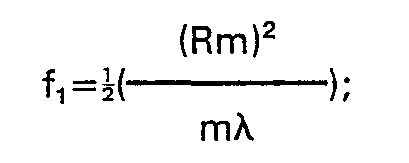
- The simplest possible treatment of the zones is to make one-half of each zone opaque. Figure 3 shows the outer half (area). of each zone made opaque, and Figure 4 shows an enlarged cross-section through the zone plate from the 4th zone to the 7th. Only the inner half of each zone (the lower half in Figure 4) is transparent to light. The action of the light passing through these half zones can be summarized to that of a series of small wavelets emerging from the mid point of each transparent half-zone. These wavelets themselves summarise to a continuous wavefront. The simplest of these is indicated by A in Figure 4 (and represents zero order transmission). Other wavefronts can be formed by connecting across the zones but with one or more waves slip between each. The important one of these is that marked B (representing positive first order diffraction) as this gives the 500 mm focal length required for the reading power add. As can be seen in the Figure 4 other wavefronts can be formed and these lead to the otherfoci; C (representing positive second order diffraction) gives the +250 mm focus and B' (representing negative first order diffraction) gives the -500 mm focus. It turns out that with the equi-transparent and opaque zone plate the energy going into the C image at 250 mm is zero. It may be noted that many textbooks divide a zone plate into half-period zones and give a mathematical treatment which applies only to the equi-transparent and opaque condition. For the present more general purpose Rm is defined as the outer radus of the mth full-period zone. This gives a focal length (f,) for the B wavefront specified by the equation:


- The treatment of the light within each zone controls the amount of light going into each focus. In the case of the equi-transparent/opaque zone plate the values are: Order

- This therefore produces relatively strong images by the zero order transmission (A) and both the positive and negative first order diffraction (B and B') wavefronts, as well as weaker images by the positive and negative third and fifth order diffraction (D, D', F, F') wavefronts. The alternate clear and opaque treatment of the half zone areas also means that 50% of the incident light is absorbed.
- Consider now replacing the opaque areas with areas which transmit the light but delay by an amount equal to one-half wavelength the wavelets now allowed through. This can be accomplished for example by overlaying these areas with a very thin layer of some transmitting optical material using the techniques of thin film deposition. The light travels more slowly through this material than through air in the adjacent area. The action in each individual area can again be summarised in terms of wavelets emerging from a central point and Figure 5 is a cross-sectional illustration similar to Figure 4. However, the raised areas mean that the (zero order transmission) wavefront A of Figure 4 is now not allowed to form (because the phase delayed wavelets are interposed) and there is no energy going into this image. As can be seen in the following table most light goes into the positive and negative first order diffraction images B and B'; Order

- Thus, although this puts more light into the positive first order diffraction image B at the expense of transmission at zero order, it also puts more into the negative first order diffraction image B'.
- In order to transfer energy from B' to B it is necessary to have within each zone an asymmetrical action on the phase delay of the light. In accordance with the invention, therefore, an asymmetric retardation of light across the zone width is provided such that light is predominantly directed into the positive first order diffraction wavefront (B) at the expense of transmission at negative first order diffraction (B'). One approach to this is to divide each zone into three equal areas (rather than the two of Figure 5) and arrange a staircase effect on the phase of the light. The phase difference between these steps within each zone must now be equivalent to A/3 where λ is the wavelength of light.
- The action of this is shown in Figure 6 which is a cross-sectional illustration similar to Figures 4 and 5. The wavefront formations are too complex to draw but the resulting intensities into each image may be calculated by the formula:

- This gives the following results:

- If the zones are each divided into four areas (instead of the three in Figure 6) while retaining the staircase action, the 1/3 value in the above formula is changed 1/4, so that:
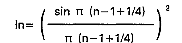

- The phase difference between these steps within each zone is now equivalent to A/4 where A is the wavelength of light.
- It can be seen that the action of increasing the number of steps in the staircase of phase delay over each zone width is to direct more and more of the light available into the positive 1st order diffraction image. The ultimate is reached when the staircase becomes a smooth curve. Because each zone was divided into equal areas (giving equal intensity and amplitude) to form the staircase, the width of each respective area decreases from the inner edge of each zone to the outer edge. However, the step rise is the same in each case. Accordingly, as more and more steps are introduced the overall shape or contour becomes a curve and not a straight line. Figure 7 shows the transition from six stepped areas to a continuous line. In this latter case it can be seen that the total change in phase at the edge of the zone is where X is the wavelength of light.
- The preceding explanation refers simply to the wavelength of light but the wavelength of visible light is not a single value. The human eye can see a range of wavelengths which it describes as colour, and the spectrum of colours changes from blue through green and yellow to red. The wavelength of blue light is about 400 nanometres (0.4 micrometres) and that of red light about 700 nanometres (0.7 micrometres). Although it is possible to design a diffractive lens to have the values tabled above, these will only apply for a single wavelength of light. This single wavelength (usually called the design wavelength) may be any value in or near the visible range indicated but it will be found that light of other wavelengths will form images at different foci and different intensities.
- If a design wavelength of 400 nanometres is assumed, then the proportions of light at wavelengths over the visible spectrum which go into the different images are indicated in Figure 8, in which (i) represents the equi-transparent/opaque areas case (Figure 4), (ii) the two stepped transparent areas case (Figure 5), (iii) the three stepped transparent areas case (Figure 6), and (iv) the continuous line (smooth curve) case (Figure 7). From these graphs it is seen that with the exception of the equi-transparent/opaque zone plate design all the systems show a reduction in the intensity of the first order diffraction B image as wavelengths different from the design wavelength are considered. Most of this loss appears as an increase in intensity for the zero order transmission A image which has infinite focal length. Thus light of a wavelength displaced from the design wavelength is predominantly transmitted at zero order in preference to positive first order diffraction. The physical reason for this change with wavelength is that the material added (in Figure 5 for example) provides the "correct" delay to the light only for a particular wavelength. Although its refractive index changes with wavelength, this is only a small change. The delay is given by the product of index difference and thickness as a proportion of the wavelength. Thus, while an index difference of 0.5 and a thickness of 0.8 micrometres gives a delay of 400 nanometres compared to the same thickness of air, which is about one wavelength for Blue light of
wavelength 400 nanometres, this same delay is 0.57 wavelengths for Red light ofwavelength 700 nanometres. - It is also important to note that the location of each image is different for light of different wavelengths. The formula for the focal length of each order of wavefront contains X, the wavelength of light, in its denominator. Thus, as the wavelength is increased (going towards Red light) the focal length is shortened. However, the eye also has a change in its focal length with wavelength. The value of the effect in the eye is in the opposite sense to that with a diffractive lens of positive power. Accordingly, for the first order diffraction B image with a required focal length of 500 mm (2 dioptres) at the design wavelength of 400 nanometres; the focal length for Red light of 700 nm is only 285 mm (3.5D). However, this change of 1.5D is virtually nullified by the eye having a change over the sume wavelength difference of -1.0D.
- It will thus be seen that a contact lens with a phase zone-plate having three or more stepped areas, or a corresponding smooth curve, across each zone width, can provide an add of +2 dioptres or thereabouts where the light in the add is predominantly Blue while the refractive power (if any) of the contact lens can correct any ametropia to give distance vision predominantly in the Red. Hence, blue light from a near object can be focussed by way of positive first order diffraction and red light from a far object can be focussed by way of zero order transmission.
- Returning now to the contours shown in profile in Figures 6 and 7, it should be recognised that these are shown as drawn on flat substrates, whereas the surfaces of a contact lens are curved. A typical
rear surface curve 8 mm radius has been indicated. The required surface contour can be superimposed on the base curve in a manner which effectively retains the basic curvature. Although there is no change in curvature when surface layers are added, it will be appreciated that the extra thickness can be considered either as changing the centre of curvature but keeping the same radius or as very slightly shortening the radius of curvature. Figure 9, in which 't' indicates the extra thickness for the stepped areas (or corresponding smooth curve) and R1 and R2 respective radii of curvature, shows the difference. - If the extra thickness is formed by thin-film deposition of extra layers where the molecules of the film material are shot at the curve from a long distance, then the representation of Figure 9(a) is the more exact. However, if the extra thickness is imparted during the making of the whole surface (e.g. using single-point diamond turning) thsn either representation may be valid or even a mixture of the two. Because the thickness changes (2 or 3µm) are very small compared to the basic radius of curvature (8 mm, which is 8000 µm) there is no appreciable difference in their effect. However, the alternatives may generate some confusion when defining the smooth curves in the ultimate case of Figure 7. When the exact curved profile is added to the base curve of 8 mm radius, it is found that a new curvature is generated. In the case of the rear surface of a contact lens the material forming the profile is likely to have a refractive index of 1.48 while the tear fluid filling the troughs of the profile is of refractive index 1.33. Thus Δn, the difference in refractive index, is 0.15. Hence the rear surface of the contact lens has an optical power given by -An/r dioptres (where r is the radius of curvature in metres) which calculates to be

- It can be calculated what radius of curvature would be needed to change this to -16.75 dioptres, as such a change would provide a reading add of 2 dioptres. This value is nearly 9 mm. On the other hand if the effect is calculated of adding the profile of Figure 7 to the 8 mm radius base curve, the new surface is found also to be a curve of radius nearly 9 mm. The difference in the phase zone plate concept is that this new curvature only extends as far as the boundary of the first full-wave zone. At that point a sharp change is allowed in the surface location equivalent to a phase delay of one wavelength at the design wavelength chosen. It is found by calculation that this is the same step size as brings the surface back to the 8 mm radius curve. The profile of the second zone starts at this point and this too gives a radius of curvature of nearly 9 mm. Again, this proceeds outwards until the boundary of the second zone. At this point it is one wavelength step size away from the 8 mm radius base curve. Thus the series of zones each having a radius of curvature of 9 mm is set on a curvature of
radius 8 mm traced out by the edges of the zones. This 8 mm radius curve is also traced out by the lower edges of each step. The two 8 mm radius curves are in fact one step size apart. - The arrangement is illustrated in Figure 10 which shows part of the rear surface of a bifocal contact lens comprising a plurality of concentric zones of the same size as in a phase zone plate, the zones being defined by steps 4 between smooth curved zone areas 5 of 9 mm radius of curvature, the step size being such that the step top edges lie on a curve of 8 mm radius of curvature and the step bottom edges lie on another curve of 8 mm radius of curvature. In Figure 10, which is not to scale, the step sizes are magnified more than the zone sizes in order to exaggerate the effect.
- In the case of zones with stepped areas as shown in Figure 6, the 8 mm radius of curvature value is not changed, but the location of this surface is shifted at each step and returned at the end of eacn zone. Figure 11 shows part of the rear surface of a bifocal contact lens comprising a plurality of concentric zones of the same size as in a phase zone plate, the zones being defined by
steps 6 and each zone having three steppedareas - Thus in both these arrangements a curvature of one radius is made discontinuous so that it approximates to another curvature of different radius, even though the other curvature does not exist at any one place. A convenient analogy is that of a tiled roof where each individual tile slopes at a given angle but the slope (or pitch) of the whole roof is at a different angle. By such discontinuous arrangement a lens incorporating a phase zone plate can effectively achieve two curvatures (and therefore two focal lengths and focal powers) for one general surface.
- The manufacture of such surfaces can utilise thin-film deposition methods, particularly when this can be applied to a mould from which many lenses may be cast or moulded. A further method of manufacture is the direct cutting of the surface using a high precision lathe. The cutting point is often a single point diamond and surfaces of good optical quality can be achieved. Such lathes have computer control systems which can position the cutting diamond to within one 11m and can return centre of rotation of the diamond-carrying arm to the same position within ±0.2 µm. From Figure 10 it can be seen that a lathe set up to turn a radius of 9 mm could be shifted at each zone edge by the one wavelength delay step size and continue cutting the 9 mm radius until the second zone edge, etc. Alternatively, a lathe set up to cut 8 mm radius could be used to cut such a curve across the whole lens and then return to cut the same radius but at slightly lower depths at the positions marked as 8 and 9 on Figure 11.
- From the foregoing it will be seen that the resultant lens surface is a smooth curve interrupted in a regular series of discrete steps of related size. The curvature of the smooth curve determines one focus of the bifocal action wihle the regular series of steps determines the other focus of the bifocal action. The proportion of the available light which goes into these foci is determined by the sizes of the steps.
- It will be appreciated that any of the zones or steps within each zone may be shifted by an amount equal to one wavelength (or multiples of one wavelength) delay at the design wavelength. The purpose of this is to affect the rate of change-over of intensity between the two images as the wavelength of the incident light is changed. Thus, for example, the second zone may be raised by one wavelength and also the third or fourth zones. The performance of the phase zone plate at the design wavelength is impervious to shifts of one (or multiples of one) wavelength.
- As specifically described above the diffractive power is given by a series of circular hills (or valleys) on the contact lens rear surface, i.e. a surface relief hologram. It will be appreciated that a surface relief hologram could instead be on the front surface of the contact lens. It will further be appreciated that the diffractive power could be provided by refractive index changes instead of surface relief or thickness changes, or by a combination of refractive index and thickness changes. In each case the changes should be such as to provide the required asymmetric retardation of light across each zone width. Yet further, although the contact lens is described above as having refractive power resulting from the material of the lens and the basic curvature of its surfaces, the contact lens curve have zero refractive power so that its optical power is wholly diffractive. Still further, although the order of diffraction into one sign (described above as positive) of which light of the design wavelength is predominantly directed is preferably, as described above, the first order, some other order coulf be employed with the lens appropriately designed predominantly to direct light of the design wavelength into one sign of that other order of diffraction. The design wavelength of 400 nanometres (blue light) mentioned above is a particularly suitable design wavelength being well displaced from the 700 nanometres wavelength (red light) which is predominantly transmitted at zero order, but is of course given by way of example and some other design wavelength could be used.
Claims (10)
Applications Claiming Priority (2)
| Application Number | Priority Date | Filing Date | Title |
|---|---|---|---|
| GB8230621 | 1982-10-27 | ||
| GB8230621 | 1982-10-27 |
Publications (3)
| Publication Number | Publication Date |
|---|---|
| EP0109753A2 EP0109753A2 (en) | 1984-05-30 |
| EP0109753A3 EP0109753A3 (en) | 1985-01-09 |
| EP0109753B1 true EP0109753B1 (en) | 1988-07-27 |
Family
ID=10533855
Family Applications (1)
| Application Number | Title | Priority Date | Filing Date |
|---|---|---|---|
| EP83306247A Expired EP0109753B1 (en) | 1982-10-27 | 1983-10-14 | Bifocal contact lens comprising a plurality of concentric zones |
Country Status (7)
| Country | Link |
|---|---|
| US (1) | US4637697A (en) |
| EP (1) | EP0109753B1 (en) |
| JP (1) | JPS59104622A (en) |
| AU (1) | AU558519B2 (en) |
| DE (1) | DE3377535D1 (en) |
| GB (1) | GB2129157B (en) |
| IE (1) | IE56087B1 (en) |
Cited By (1)
| Publication number | Priority date | Publication date | Assignee | Title |
|---|---|---|---|---|
| US7497572B2 (en) | 2006-07-17 | 2009-03-03 | Novartis Ag | Toric contact lenses with controlled optical power profile |
Families Citing this family (255)
| Publication number | Priority date | Publication date | Assignee | Title |
|---|---|---|---|---|
| US4580882A (en) * | 1983-04-21 | 1986-04-08 | Benjamin Nuchman | Continuously variable contact lens |
| EP0201231A3 (en) * | 1985-05-03 | 1989-07-12 | THE COOPER COMPANIES, INC. (formerly called CooperVision, Inc.) | Method of treating presbyopia with concentric bifocal contact lenses |
| US5017000A (en) * | 1986-05-14 | 1991-05-21 | Cohen Allen L | Multifocals using phase shifting |
| US5144483A (en) * | 1986-05-14 | 1992-09-01 | Cohen Allen L | Diffractive multifocal optical device |
| US5121979A (en) * | 1986-05-14 | 1992-06-16 | Cohen Allen L | Diffractive multifocal optical device |
| JPS6347982A (en) * | 1986-08-18 | 1988-02-29 | Sharp Corp | Semiconductor device |
| JPH0336977Y2 (en) * | 1986-12-17 | 1991-08-06 | ||
| US4898461A (en) * | 1987-06-01 | 1990-02-06 | Valdemar Portney | Multifocal ophthalmic lens |
| US5166712A (en) * | 1987-06-01 | 1992-11-24 | Valdemar Portney | Multifocal ophthalmic lens |
| US5225858A (en) * | 1987-06-01 | 1993-07-06 | Valdemar Portney | Multifocal ophthalmic lens |
| US5166711A (en) * | 1987-06-01 | 1992-11-24 | Valdemar Portney | Multifocal ophthalmic lens |
| US5270744A (en) * | 1987-06-01 | 1993-12-14 | Valdemar Portney | Multifocal ophthalmic lens |
| US4895790A (en) * | 1987-09-21 | 1990-01-23 | Massachusetts Institute Of Technology | High-efficiency, multilevel, diffractive optical elements |
| US5161059A (en) * | 1987-09-21 | 1992-11-03 | Massachusetts Institute Of Technology | High-efficiency, multilevel, diffractive optical elements |
| US4936665A (en) * | 1987-10-25 | 1990-06-26 | Whitney Theodore R | High resolution imagery systems and methods |
| US5156943A (en) * | 1987-10-25 | 1992-10-20 | Whitney Theodore R | High resolution imagery systems and methods |
| US4881805A (en) * | 1987-11-12 | 1989-11-21 | Cohen Allen L | Progressive intensity phase bifocal |
| US5056908A (en) * | 1987-11-12 | 1991-10-15 | Cohen Allen L | Optic zone phase channels |
| US4881804A (en) * | 1987-11-12 | 1989-11-21 | Cohen Allen L | Multifocal phase plate with a pure refractive portion |
| US5009497A (en) * | 1987-11-12 | 1991-04-23 | Cohen Allen L | Contact lenses utilizing keel orientation |
| CA1316728C (en) * | 1988-04-01 | 1993-04-27 | Michael J. Simpson | Multi-focal diffractive ophthalmic lenses |
| US5089024A (en) * | 1988-04-19 | 1992-02-18 | Storz Instrument Company | Multi-focal intraocular lens |
| FR2631713B1 (en) * | 1988-05-19 | 1990-08-31 | Essilor Int | DIFFRACTIVE LENS WITH MIXED PROFILE |
| US4848894A (en) * | 1988-06-01 | 1989-07-18 | The United States Of America As Represented By The Secretary Of The Army | Contact lens with laser protection |
| ATE133796T1 (en) | 1988-07-20 | 1996-02-15 | Allen L Dr Cohen | MULTIFOCAL DIFFRACTIVE OPTICAL DEVICE |
| US5192317A (en) * | 1988-07-26 | 1993-03-09 | Irvin Kalb | Multi focal intra-ocular lens |
| US4932966A (en) * | 1988-08-15 | 1990-06-12 | Storz Instrument Company | Accommodating intraocular lens |
| US4995714A (en) * | 1988-08-26 | 1991-02-26 | Cohen Allen L | Multifocal optical device with novel phase zone plate and method for making |
| IE73284B1 (en) * | 1988-08-26 | 1997-05-21 | Allen L Cohen | The invention relates to a method of manufacturing a multifocal diffractive optical element |
| US5161057A (en) * | 1988-09-12 | 1992-11-03 | Johnson Kenneth C | Dispersion-compensated fresnel lens |
| AU630890B2 (en) * | 1988-09-12 | 1992-11-12 | Kenneth C. Johnson | Dispersion-compensating diffraction grating |
| US5013133A (en) * | 1988-10-31 | 1991-05-07 | The University Of Rochester | Diffractive optical imaging lens systems |
| FR2638859B1 (en) * | 1988-11-09 | 1991-02-08 | Essilor Int | ENGRAVED DIFFRACTIVE OPHTHALMIC LENS |
| GB8829819D0 (en) * | 1988-12-21 | 1989-02-15 | Freeman Michael H | Lenses and mirrors |
| FR2642855B1 (en) * | 1989-02-06 | 1991-05-17 | Essilor Int | OPTICAL LENS FOR THE CORRECTION OF ASTIGMATISM |
| US5073021A (en) * | 1989-03-17 | 1991-12-17 | Environmental Research Institute Of Michigan | Bifocal ophthalmic lens constructed from birefringent material |
| US5175651A (en) * | 1989-03-17 | 1992-12-29 | Environmental Research Institute Of Michigan | Multi-focus system for a low light level vision apparatus |
| GB2237122B (en) * | 1989-10-16 | 1993-10-27 | Combined Optical Ind Ltd | Improved fresnel lens |
| US5002382A (en) * | 1989-12-07 | 1991-03-26 | Leonard Seidner | Multifocal corneal contact lenses |
| US5024517A (en) * | 1989-12-07 | 1991-06-18 | Leonard Seidner | Monovision corneal contact lenses |
| US5135592A (en) * | 1989-12-27 | 1992-08-04 | Minnesota Mining And Manufacturing Company | Ultrasonically welded hydrogel ophthalmic lens |
| US5152788A (en) * | 1989-12-27 | 1992-10-06 | Minnesota Mining And Manufacturing Company | Multifocal diffractive ophthalmic lens and method of manufacture |
| US5227915A (en) * | 1990-02-13 | 1993-07-13 | Holo-Or Ltd. | Diffractive optical element |
| WO1991012551A1 (en) * | 1990-02-14 | 1991-08-22 | Massachusetts Institute Of Technology | Lens/zone plate combination for chromatic dispersion correction |
| GB9008577D0 (en) * | 1990-04-17 | 1990-06-13 | Pilkington Diffractive Lenses | Rigid gas permeable lenses |
| GB9008580D0 (en) * | 1990-04-17 | 1990-06-13 | Pilkington Diffractive Lenses | Manufacture of contact lenses |
| GB9008582D0 (en) * | 1990-04-17 | 1990-06-13 | Pilkington Diffractive Lenses | Method and contact lenses for treating presbyobia |
| US5181053A (en) * | 1990-05-10 | 1993-01-19 | Contact Lens Corporation Of America | Multi-focal contact lens |
| US5178636A (en) * | 1990-05-14 | 1993-01-12 | Iolab Corporation | Tuned fresnel lens for multifocal intraocular applications including small incision surgeries |
| US5096285A (en) * | 1990-05-14 | 1992-03-17 | Iolab Corporation | Multifocal multizone diffractive ophthalmic lenses |
| US5073007A (en) * | 1990-06-11 | 1991-12-17 | Holo-Or Ltd. | Diffractive optical element |
| US5229797A (en) * | 1990-08-08 | 1993-07-20 | Minnesota Mining And Manufacturing Company | Multifocal diffractive ophthalmic lenses |
| US5071207A (en) * | 1990-09-25 | 1991-12-10 | The United States Of America As Represented By The United States Department Of Energy | Broadband diffractive lens or imaging element |
| US5144484A (en) * | 1990-10-15 | 1992-09-01 | Rockwell International Corporation | Binary optic lens design using flip-flop optimization |
| US5260727A (en) * | 1990-10-22 | 1993-11-09 | Oksman Henry C | Wide depth of focus intraocular and contact lenses |
| JPH04361201A (en) * | 1991-06-10 | 1992-12-14 | Olympus Optical Co Ltd | Optical system using fresnel zone plate |
| US5153778A (en) * | 1991-06-19 | 1992-10-06 | At&T Bell Laboratories | Powerless field-corrective lens |
| US5148317A (en) * | 1991-06-24 | 1992-09-15 | The United States Of America As Represented By The Secretary Of The Air Force | Diffractive optical element for collimating and redistributing Gaussian input beam |
| US5257133A (en) * | 1991-09-11 | 1993-10-26 | Hughes Aircraft Company | Re-imaging optical system employing refractive and diffractive optical elements |
| DE4134518A1 (en) * | 1991-10-18 | 1993-04-22 | Adatomed Pharma & Med | OPHTHALMIC LENS |
| US5260828A (en) * | 1992-03-27 | 1993-11-09 | Polaroid Corporation | Methods and means for reducing temperature-induced variations in lenses and lens devices |
| US5344447A (en) * | 1992-11-12 | 1994-09-06 | Massachusetts Institute Of Technology | Diffractive trifocal intra-ocular lens design |
| US5760871A (en) * | 1993-01-06 | 1998-06-02 | Holo-Or Ltd. | Diffractive multi-focal lens |
| US5748282A (en) * | 1993-01-27 | 1998-05-05 | Pilkington Barnes Hind, Inc. | Multifocal contact lens |
| GB9301614D0 (en) * | 1993-01-27 | 1993-03-17 | Pilkington Diffractive Lenses | Multifocal contact lens |
| US5815293A (en) * | 1993-02-01 | 1998-09-29 | Matsushita Electric Industrial Co., Ltd. | Compound objective lens having two focal points |
| JP2532818B2 (en) * | 1993-02-01 | 1996-09-11 | 松下電器産業株式会社 | Objective lens and optical head device |
| US5408281A (en) * | 1993-04-26 | 1995-04-18 | Ciba-Geigy | Multifocal contact lens |
| JPH0749471A (en) * | 1993-08-06 | 1995-02-21 | Kuraray Co Ltd | Eye mirror |
| US5543816A (en) * | 1993-10-07 | 1996-08-06 | Virtual Vision | Head mounted display system with aspheric optics |
| US5517260A (en) * | 1994-03-28 | 1996-05-14 | Vari-Site, Inc. | Ophthalmic lens having a progressive multifocal zone and method of manufacturing same |
| US5589982A (en) * | 1994-06-03 | 1996-12-31 | Rochester Photonics Corporation | Polychromatic diffractive lens |
| US5861114A (en) * | 1994-06-10 | 1999-01-19 | Johnson&Johnson Vision Products, Inc. | Method of manufacturing complex optical designs in soft contact lenses |
| US5699142A (en) * | 1994-09-01 | 1997-12-16 | Alcon Laboratories, Inc. | Diffractive multifocal ophthalmic lens |
| US20090069817A1 (en) * | 1995-10-20 | 2009-03-12 | Acufocus, Inc. | Intrastromal corneal modification |
| US5702440A (en) * | 1996-01-26 | 1997-12-30 | Allergan | Multifocal ophthalmic lens for dim-lighting conditions |
| US5864378A (en) * | 1996-05-21 | 1999-01-26 | Allergan | Enhanced monofocal IOL or contact lens |
| US5898473A (en) * | 1997-04-25 | 1999-04-27 | Permeable Technologies, Inc. | Multifocal corneal contact lens |
| GB9710781D0 (en) * | 1997-05-23 | 1997-07-23 | Ng Trustees & Nominees Ltd | Decentred bifocal contact lenses |
| US5980040A (en) * | 1997-06-30 | 1999-11-09 | Wesley Jessen Corporation | Pinhole lens and contact lens |
| US6158862A (en) * | 1997-12-04 | 2000-12-12 | Alcon Laboratories, Inc. | Method of reducing glare associated with multifocal ophthalmic lenses |
| US6139146A (en) * | 1997-12-29 | 2000-10-31 | Novartis Ag | Programmable corrective lenses |
| US6139147A (en) * | 1998-11-20 | 2000-10-31 | Novartis Ag | Actively controllable multifocal lens |
| US5997140A (en) * | 1997-12-29 | 1999-12-07 | Novartis Ag | Actively controllable multifocal lens |
| IL123574A0 (en) | 1998-03-05 | 1998-10-30 | Holo Or Ltd | Progressive multifocal lens construction for eyeglasses |
| US6012814A (en) * | 1998-05-28 | 2000-01-11 | University Of New Mexico | Extraocular muscle tester |
| IL124991A (en) * | 1998-06-18 | 2002-12-01 | Rotlex 1994 Ltd | Multifocal lens combining the advantages of progressive addition lenses and diffractive lenses |
| CA2339776C (en) | 1998-08-06 | 2005-10-25 | John B. W. Lett | Multifocal aspheric lens |
| US6120148A (en) * | 1998-10-05 | 2000-09-19 | Bifocon Optics Gmbh | Diffractive lens |
| US6231603B1 (en) | 1998-11-10 | 2001-05-15 | Allergan Sales, Inc. | Accommodating multifocal intraocular lens |
| CA2351435A1 (en) * | 1998-12-16 | 2000-06-22 | William Rovani | Multifocal contact lens with aspheric surface |
| US6210005B1 (en) | 1999-02-04 | 2001-04-03 | Valdemar Portney | Multifocal ophthalmic lens with reduced halo size |
| US6554424B1 (en) * | 1999-03-01 | 2003-04-29 | Boston Innovative Optices, Inc. | System and method for increasing the depth of focus of the human eye |
| US20060238702A1 (en) | 1999-04-30 | 2006-10-26 | Advanced Medical Optics, Inc. | Ophthalmic lens combinations |
| US20030060881A1 (en) * | 1999-04-30 | 2003-03-27 | Advanced Medical Optics, Inc. | Intraocular lens combinations |
| US6790232B1 (en) | 1999-04-30 | 2004-09-14 | Advanced Medical Optics, Inc. | Multifocal phakic intraocular lens |
| US6406494B1 (en) | 1999-04-30 | 2002-06-18 | Allergan Sales, Inc. | Moveable intraocular lens |
| US6616692B1 (en) | 1999-04-30 | 2003-09-09 | Advanced Medical Optics, Inc. | Intraocular lens combinations |
| US6645246B1 (en) | 1999-09-17 | 2003-11-11 | Advanced Medical Optics, Inc. | Intraocular lens with surrounded lens zone |
| US6599317B1 (en) | 1999-09-17 | 2003-07-29 | Advanced Medical Optics, Inc. | Intraocular lens with a translational zone |
| US6250757B1 (en) | 1999-12-15 | 2001-06-26 | Johnson & Johnson Vision Products, Inc. | Hybrid refractive birefringent multifocal ophthalmic lenses |
| US6551354B1 (en) * | 2000-03-09 | 2003-04-22 | Advanced Medical Optics, Inc. | Accommodating intraocular lens |
| US6537317B1 (en) | 2000-05-03 | 2003-03-25 | Advanced Medical Optics, Inc. | Binocular lens systems |
| US6554859B1 (en) | 2000-05-03 | 2003-04-29 | Advanced Medical Optics, Inc. | Accommodating, reduced ADD power multifocal intraocular lenses |
| US6547822B1 (en) | 2000-05-03 | 2003-04-15 | Advanced Medical Optics, Inc. | Opthalmic lens systems |
| US6660035B1 (en) | 2000-08-02 | 2003-12-09 | Advanced Medical Optics, Inc. | Accommodating intraocular lens with suspension structure |
| AU2001287997A1 (en) * | 2000-09-29 | 2002-04-08 | Werner J. Fiala | Ophthalmic lens with surface structures |
| US6586499B2 (en) * | 2000-12-19 | 2003-07-01 | Bausch & Lomb Incorporated | Water-soluble blocking wax formulation |
| US20020093701A1 (en) * | 2000-12-29 | 2002-07-18 | Xiaoxiao Zhang | Holographic multifocal lens |
| US7087080B2 (en) * | 2001-01-25 | 2006-08-08 | Visiogen, Inc. | Materials for use in intraocular lens system |
| US20030078657A1 (en) | 2001-01-25 | 2003-04-24 | Gholam-Reza Zadno-Azizi | Materials for use in accommodating intraocular lens system |
| US20030078658A1 (en) * | 2001-01-25 | 2003-04-24 | Gholam-Reza Zadno-Azizi | Single-piece accomodating intraocular lens system |
| US7780729B2 (en) * | 2004-04-16 | 2010-08-24 | Visiogen, Inc. | Intraocular lens |
| US8062361B2 (en) | 2001-01-25 | 2011-11-22 | Visiogen, Inc. | Accommodating intraocular lens system with aberration-enhanced performance |
| US20120016349A1 (en) | 2001-01-29 | 2012-01-19 | Amo Development, Llc. | Hybrid ophthalmic interface apparatus and method of interfacing a surgical laser with an eye |
| US6596025B2 (en) | 2001-03-15 | 2003-07-22 | Valdemar Portney | Narrow profile intraocular lens |
| US6576012B2 (en) | 2001-03-28 | 2003-06-10 | Advanced Medical Optics, Inc. | Binocular lens systems |
| SE0101293D0 (en) * | 2001-04-11 | 2001-04-11 | Pharmacia Groningen Bv | Technical field of the invention |
| US6638305B2 (en) | 2001-05-15 | 2003-10-28 | Advanced Medical Optics, Inc. | Monofocal intraocular lens convertible to multifocal intraocular lens |
| DE60230173D1 (en) * | 2001-10-19 | 2009-01-15 | Bausch & Lomb | presbyopia |
| EP1902672B1 (en) * | 2001-10-19 | 2010-04-28 | Bausch & Lomb Incorporated | Presbyopic vision improvement |
| US7025783B2 (en) * | 2002-01-14 | 2006-04-11 | Advanced Medical Optics, Inc. | Accommodating intraocular lens with integral capsular bag ring |
| US7326246B2 (en) * | 2002-01-14 | 2008-02-05 | Advanced Medical Optics, Inc. | Accommodating intraocular lens with elongated suspension structure |
| US7763069B2 (en) | 2002-01-14 | 2010-07-27 | Abbott Medical Optics Inc. | Accommodating intraocular lens with outer support structure |
| US7150759B2 (en) * | 2002-01-14 | 2006-12-19 | Advanced Medical Optics, Inc. | Multi-mechanistic accommodating intraocular lenses |
| US6972033B2 (en) * | 2002-08-26 | 2005-12-06 | Advanced Medical Optics, Inc. | Accommodating intraocular lens assembly with multi-functional capsular bag ring |
| US6851803B2 (en) | 2002-10-24 | 2005-02-08 | C. Benjamin Wooley | Ophthalmic lenses with reduced chromatic blur |
| US20040082993A1 (en) | 2002-10-25 | 2004-04-29 | Randall Woods | Capsular intraocular lens implant having a refractive liquid therein |
| US7896916B2 (en) | 2002-11-29 | 2011-03-01 | Amo Groningen B.V. | Multifocal ophthalmic lens |
| SE0203564D0 (en) * | 2002-11-29 | 2002-11-29 | Pharmacia Groningen Bv | Multifocal opthalmic lens |
| US7662180B2 (en) | 2002-12-05 | 2010-02-16 | Abbott Medical Optics Inc. | Accommodating intraocular lens and method of manufacture thereof |
| US7063422B2 (en) | 2003-04-16 | 2006-06-20 | Novartis Ag | Multifocal ophthalmic lens |
| US6896368B2 (en) * | 2003-05-07 | 2005-05-24 | Thomas K. Baugh | Multifocal soft contact lens with horizontally decentered lenslet and indicator marking |
| US7628810B2 (en) * | 2003-05-28 | 2009-12-08 | Acufocus, Inc. | Mask configured to maintain nutrient transport without producing visible diffraction patterns |
| US6951391B2 (en) * | 2003-06-16 | 2005-10-04 | Apollo Optical Systems Llc | Bifocal multiorder diffractive lenses for vision correction |
| US20050046794A1 (en) * | 2003-06-17 | 2005-03-03 | Silvestrini Thomas A. | Method and apparatus for aligning a mask with the visual axis of an eye |
| EP1639398B9 (en) * | 2003-06-30 | 2012-02-22 | Werner Fiala | Intra-ocular lens or contact lens exhibiting large depth of focus |
| US20050027354A1 (en) * | 2003-07-28 | 2005-02-03 | Advanced Medical Optics, Inc. | Primary and supplemental intraocular lens |
| US20050131535A1 (en) * | 2003-12-15 | 2005-06-16 | Randall Woods | Intraocular lens implant having posterior bendable optic |
| US7025456B2 (en) * | 2004-08-20 | 2006-04-11 | Apollo Optical Systems, Llc | Diffractive lenses for vision correction |
| US7156516B2 (en) * | 2004-08-20 | 2007-01-02 | Apollo Optical Systems Llc | Diffractive lenses for vision correction |
| US7506983B2 (en) | 2004-09-30 | 2009-03-24 | The Hong Kong Polytechnic University | Method of optical treatment |
| CA2614519A1 (en) * | 2004-10-22 | 2006-05-04 | Omer Yilmaz | System and method for aligning an optic with an axis of an eye |
| WO2006047698A1 (en) * | 2004-10-25 | 2006-05-04 | Advanced Medical Optics, Inc. | Ophthalmic lens with multiple phase plates |
| US7922326B2 (en) | 2005-10-25 | 2011-04-12 | Abbott Medical Optics Inc. | Ophthalmic lens with multiple phase plates |
| US8377123B2 (en) * | 2004-11-10 | 2013-02-19 | Visiogen, Inc. | Method of implanting an intraocular lens |
| US20060113054A1 (en) * | 2004-12-01 | 2006-06-01 | Silvestrini Thomas A | Method of making an ocular implant |
| US7491350B2 (en) * | 2004-12-01 | 2009-02-17 | Acufocus, Inc. | Method of making an ocular implant |
| US7976577B2 (en) * | 2005-04-14 | 2011-07-12 | Acufocus, Inc. | Corneal optic formed of degradation resistant polymer |
| US20060235428A1 (en) * | 2005-04-14 | 2006-10-19 | Silvestrini Thomas A | Ocular inlay with locator |
| US8579970B1 (en) | 2005-06-27 | 2013-11-12 | Visiogen, Inc. | Magnifying intraocular lens |
| US9636213B2 (en) | 2005-09-30 | 2017-05-02 | Abbott Medical Optics Inc. | Deformable intraocular lenses and lens systems |
| US7172285B1 (en) | 2005-12-09 | 2007-02-06 | Bausch & Lomb Incorporated | Contact lens with high-order compensation for non-axisymmetric structure |
| US20070168027A1 (en) * | 2006-01-13 | 2007-07-19 | Brady Daniel G | Accommodating diffractive intraocular lens |
| US20070258143A1 (en) * | 2006-05-08 | 2007-11-08 | Valdemar Portney | Aspheric multifocal diffractive ophthalmic lens |
| US20070273983A1 (en) * | 2006-05-26 | 2007-11-29 | Hebert Raymond T | Devices, methods, and systems for image viewing |
| WO2007141788A2 (en) * | 2006-06-06 | 2007-12-13 | Xceed Imaging Ltd. | Optical system and method for multi-range and dual-range imaging |
| US8619362B2 (en) * | 2006-08-01 | 2013-12-31 | Valdemar Portney | Multifocal diffractive ophthalmic lens with multifocal base surface |
| AU2007338100B2 (en) | 2006-12-22 | 2014-01-30 | Amo Groningen Bv | Accommodating intraocular lens, lens system and frame therefor |
| US20080161914A1 (en) * | 2006-12-29 | 2008-07-03 | Advanced Medical Optics, Inc. | Pre-stressed haptic for accommodating intraocular lens |
| CA2674018C (en) | 2006-12-29 | 2015-05-26 | Advanced Medical Optics, Inc. | Multifocal accommodating intraocular lens |
| US7713299B2 (en) | 2006-12-29 | 2010-05-11 | Abbott Medical Optics Inc. | Haptic for accommodating intraocular lens |
| US20090228101A1 (en) | 2007-07-05 | 2009-09-10 | Visiogen, Inc. | Intraocular lens with post-implantation adjustment capabilities |
| FR2918557B1 (en) * | 2007-07-09 | 2009-10-02 | Gilbert Cohen | INTRACORNEAN DIFFRACTIVE LENS. |
| US8974526B2 (en) * | 2007-08-27 | 2015-03-10 | Amo Groningen B.V. | Multizonal lens with extended depth of focus |
| US8740978B2 (en) | 2007-08-27 | 2014-06-03 | Amo Regional Holdings | Intraocular lens having extended depth of focus |
| US20090062911A1 (en) | 2007-08-27 | 2009-03-05 | Amo Groningen Bv | Multizonal lens with extended depth of focus |
| US8747466B2 (en) * | 2007-08-27 | 2014-06-10 | Amo Groningen, B.V. | Intraocular lens having extended depth of focus |
| US9216080B2 (en) | 2007-08-27 | 2015-12-22 | Amo Groningen B.V. | Toric lens with decreased sensitivity to cylinder power and rotation and method of using the same |
| WO2009066446A1 (en) * | 2007-11-20 | 2009-05-28 | Panasonic Corporation | Beam scanned type display device, display method, and automobile |
| CA2715537C (en) | 2008-02-15 | 2016-09-06 | Amo Regional Holdings | System, ophthalmic lens, and method for extending depth of focus |
| US8439498B2 (en) | 2008-02-21 | 2013-05-14 | Abbott Medical Optics Inc. | Toric intraocular lens with modified power characteristics |
| DE202008003859U1 (en) | 2008-03-19 | 2009-08-13 | Icon Lab Gmbh | Multifocal intraocular lens |
| US8034108B2 (en) * | 2008-03-28 | 2011-10-11 | Abbott Medical Optics Inc. | Intraocular lens having a haptic that includes a cap |
| US8231219B2 (en) * | 2008-04-24 | 2012-07-31 | Amo Groningen B.V. | Diffractive lens exhibiting enhanced optical performance |
| US7871162B2 (en) * | 2008-04-24 | 2011-01-18 | Amo Groningen B.V. | Diffractive multifocal lens having radially varying light distribution |
| US8862447B2 (en) | 2010-04-30 | 2014-10-14 | Amo Groningen B.V. | Apparatus, system and method for predictive modeling to design, evaluate and optimize ophthalmic lenses |
| US20090306773A1 (en) * | 2008-06-04 | 2009-12-10 | Acufocus, Inc. | Opaque corneal insert for refractive correction |
| US20100188636A1 (en) * | 2008-07-30 | 2010-07-29 | Pinto Candido D | Multifocal ophthalmic lens having reduced ghosting |
| US8922898B2 (en) | 2008-09-04 | 2014-12-30 | Innovega Inc. | Molded lens with nanofilaments and related methods |
| US8520309B2 (en) | 2008-09-04 | 2013-08-27 | Innovega Inc. | Method and apparatus to process display and non-display information |
| US8786520B2 (en) * | 2008-09-04 | 2014-07-22 | Innovega, Inc. | System and apparatus for display panels |
| US8142016B2 (en) | 2008-09-04 | 2012-03-27 | Innovega, Inc. | Method and apparatus for constructing a contact lens with optics |
| AT507254B1 (en) * | 2008-09-09 | 2010-06-15 | Fiala Werner | LENS WITH INDEPENDENT NON-INTERFERING PARTIAL ZONES |
| US9089419B2 (en) * | 2008-10-15 | 2015-07-28 | Novartis Ag | System to reduce surface contact between optic and haptic areas |
| US8292953B2 (en) | 2008-10-20 | 2012-10-23 | Amo Groningen B.V. | Multifocal intraocular lens |
| US8216307B2 (en) * | 2008-12-19 | 2012-07-10 | Novartis Ag | Radially segmented apodized diffractive multifocal design for ocular implant |
| SG10201402266XA (en) | 2009-02-12 | 2014-10-30 | Univ Arizona State | Diffractive trifocal lens |
| NL2002540C2 (en) * | 2009-02-17 | 2010-08-18 | Oculentis B V | Ophthalmic lens with optical sectors. |
| US8486142B2 (en) | 2009-06-26 | 2013-07-16 | Abbott Medical Optics Inc. | Accommodating intraocular lenses |
| US8128222B2 (en) * | 2009-07-27 | 2012-03-06 | Valdemar Portney | Multifocal diffractive contact lens with bi-sign surface shape |
| WO2011017322A1 (en) | 2009-08-03 | 2011-02-10 | Abbott Medical Optics Inc. | Intraocular lens for providing accomodative vision |
| RU2012108951A (en) | 2009-08-13 | 2013-09-20 | Акуфокус, Инк. | HIDDED INTRAOCULAR IMPLANTS AND LENSES |
| PL2290411T3 (en) | 2009-08-27 | 2012-10-31 | Polymer Tech International Eou | Refractive-diffractive lens |
| US9370416B2 (en) | 2009-08-27 | 2016-06-21 | Jagrat Natavar DAVE | Refractive-diffractive lens |
| MX2012004531A (en) * | 2009-10-26 | 2012-06-12 | Novartis Ag | Phase-shifted center-distance diffractive design for ocular implant. |
| USD656526S1 (en) | 2009-11-10 | 2012-03-27 | Acufocus, Inc. | Ocular mask |
| CA2784782C (en) | 2009-12-18 | 2018-02-27 | Hendrik A. Weeber | Limited echelette lens, systems and methods |
| WO2011107723A1 (en) | 2010-03-05 | 2011-09-09 | John Trevor De Carle | Multifocal lens |
| WO2012004746A2 (en) | 2010-07-05 | 2012-01-12 | Polymer Technologies International (Eou) | Refractive-diffractive ophthalmic device and compositions useful for producing same |
| US9817246B2 (en) | 2010-12-01 | 2017-11-14 | Amo Groningen B.V. | Multifocal lens having an optical add power progression, and a system and method of providing same |
| US9931200B2 (en) | 2010-12-17 | 2018-04-03 | Amo Groningen B.V. | Ophthalmic devices, systems, and methods for optimizing peripheral vision |
| US8894204B2 (en) | 2010-12-17 | 2014-11-25 | Abbott Medical Optics Inc. | Ophthalmic lens, systems and methods having at least one rotationally asymmetric diffractive structure |
| WO2013082545A1 (en) | 2011-12-02 | 2013-06-06 | Acufocus, Inc. | Ocular mask having selective spectral transmission |
| US8556417B2 (en) * | 2012-02-02 | 2013-10-15 | Novartis Ag | Apodized hybrid diffractive-refractive IOL for pseudo-accommodation |
| US9084674B2 (en) | 2012-05-02 | 2015-07-21 | Abbott Medical Optics Inc. | Intraocular lens with shape changing capability to provide enhanced accomodation and visual acuity |
| BR112015004617A2 (en) | 2012-08-31 | 2017-07-04 | Amo Groningen Bv | systems and methods for extended multi-lens lens extended focus depth |
| CN104755997B (en) * | 2012-10-23 | 2016-11-16 | 埃西勒国际通用光学公司 | Systems Including Multifocal Diffractive Mirror Assemblies |
| CA2877203A1 (en) | 2012-12-04 | 2014-06-12 | Amo Groningen B.V. | Lenses, systems and methods for providing binocular customized treatments to correct presbyopia |
| EP2945570A1 (en) | 2013-01-15 | 2015-11-25 | Dave, Jagrat Natavar | Toric-diffractive lens |
| AU2014228357B2 (en) | 2013-03-11 | 2018-08-23 | Johnson & Johnson Surgical Vision, Inc. | Intraocular lens that matches an image surface to a retinal shape, and method of designing same |
| US9204962B2 (en) | 2013-03-13 | 2015-12-08 | Acufocus, Inc. | In situ adjustable optical mask |
| US9427922B2 (en) | 2013-03-14 | 2016-08-30 | Acufocus, Inc. | Process for manufacturing an intraocular lens with an embedded mask |
| CN105392455B (en) * | 2013-05-30 | 2018-04-06 | 株式会社实瞳 | ring device |
| WO2016038470A2 (en) | 2014-03-10 | 2016-03-17 | Amo Groningen B.V. | Dual-optic intraocular lens that improves overall vision where there is a local loss of retinal function |
| WO2015177651A1 (en) | 2014-04-21 | 2015-11-26 | Amo Groningen B.V. | Ophthalmic devices, system and methods that improve peripheral vision |
| US9335564B2 (en) * | 2014-05-15 | 2016-05-10 | Novartis Ag | Multifocal diffractive ophthalmic lens using suppressed diffractive order |
| WO2016034925A1 (en) | 2014-09-02 | 2016-03-10 | Dave, Jagrat Natavar | Intraocular lens customized for astigmatism or combined astigmatism and presbyopia |
| CA3013857A1 (en) | 2016-02-09 | 2017-08-17 | Amo Groningen B.V. | Progressive power intraocular lens, and methods of use and manufacture |
| EP3426191B1 (en) | 2016-03-11 | 2024-09-11 | Amo Groningen B.V. | Intraocular lenses that improve peripheral vision |
| AU2017237090B2 (en) | 2016-03-23 | 2021-10-21 | Johnson & Johnson Surgical Vision, Inc. | Ophthalmic apparatus with corrective meridians having extended tolerance band by modifying refractive powers in uniform meridian distribution |
| WO2017165623A1 (en) | 2016-03-23 | 2017-09-28 | Abbott Medical Optics Inc. | Power calculator for an ophthalmic apparatus with corrective meridians having extended tolerance or operation band |
| US11096778B2 (en) | 2016-04-19 | 2021-08-24 | Amo Groningen B.V. | Ophthalmic devices, system and methods that improve peripheral vision |
| US11013594B2 (en) | 2016-10-25 | 2021-05-25 | Amo Groningen B.V. | Realistic eye models to design and evaluate intraocular lenses for a large field of view |
| US10426599B2 (en) * | 2016-11-29 | 2019-10-01 | Novartis Ag | Multifocal lens having reduced chromatic aberrations |
| WO2018150236A1 (en) | 2017-02-14 | 2018-08-23 | Dave, Jagrat Natavar | Diffractive multifocal implantable lens device |
| US11497599B2 (en) | 2017-03-17 | 2022-11-15 | Amo Groningen B.V. | Diffractive intraocular lenses for extended range of vision |
| US10739227B2 (en) | 2017-03-23 | 2020-08-11 | Johnson & Johnson Surgical Vision, Inc. | Methods and systems for measuring image quality |
| US11523897B2 (en) | 2017-06-23 | 2022-12-13 | Amo Groningen B.V. | Intraocular lenses for presbyopia treatment |
| AU2018292030B2 (en) | 2017-06-28 | 2024-02-08 | Amo Groningen B.V. | Extended range and related intraocular lenses for presbyopia treatment |
| US11262598B2 (en) | 2017-06-28 | 2022-03-01 | Amo Groningen, B.V. | Diffractive lenses and related intraocular lenses for presbyopia treatment |
| US11327210B2 (en) | 2017-06-30 | 2022-05-10 | Amo Groningen B.V. | Non-repeating echelettes and related intraocular lenses for presbyopia treatment |
| ES2803225T3 (en) * | 2017-07-26 | 2021-01-25 | Vsy Biyoteknoloji Ve Ilac Sanayi Anonim Sirketi | Ophthalmic multifocal diffractive lens |
| EP3681438A1 (en) | 2017-09-11 | 2020-07-22 | AMO Groningen B.V. | Methods and apparatuses to increase intraocular lenses positional stability |
| DE102017123323B3 (en) | 2017-10-09 | 2019-01-24 | Jabil Optics Germany GmbH | Contact lens for use with an HMD and associated HMD |
| CN109725441A (en) * | 2017-10-28 | 2019-05-07 | 郑克立 | A kind of holographic glasses piece |
| CA3082053A1 (en) | 2017-11-30 | 2019-06-06 | Amo Groningen B.V. | Intraocular lenses that improve post-surgical spectacle independent and methods of manufacturing thereof |
| EP3811146A1 (en) * | 2018-06-20 | 2021-04-28 | Essilor International | Lens element |
| CN112867467B (en) * | 2018-09-13 | 2025-05-16 | 哈尼塔镜片公司 | Multifocal intraocular lens |
| WO2020066473A1 (en) * | 2018-09-25 | 2020-04-02 | 株式会社アイメディ商事 | Lens for smart contact lens |
| US12204178B2 (en) | 2018-12-06 | 2025-01-21 | Amo Groningen B.V. | Diffractive lenses for presbyopia treatment |
| US11106056B2 (en) | 2019-03-28 | 2021-08-31 | Aizhong Zhang | Subzonal multifocal diffractive lens |
| CN110470245B (en) * | 2019-08-21 | 2021-02-26 | 浙江大学 | Phase recovery detection device and phase recovery method based on Fresnel zone plate diffraction information fusion |
| TW202125041A (en) * | 2019-12-18 | 2021-07-01 | 瑞士商愛爾康公司 | Hybrid diffractive and refractive contact lens |
| AU2020416055B2 (en) | 2019-12-30 | 2026-04-30 | Amo Groningen B.V. | Lenses having diffractive profiles with irregular width for vision treatment |
| US11886046B2 (en) | 2019-12-30 | 2024-01-30 | Amo Groningen B.V. | Multi-region refractive lenses for vision treatment |
| JP2021140125A (en) * | 2020-03-04 | 2021-09-16 | 株式会社アイメディ商事 | Lense for smart contact lens |
| BR112022018771A2 (en) * | 2020-03-20 | 2022-11-01 | Roop Prakhyat | LENS DEVICE |
| CN114442210B (en) * | 2020-11-04 | 2025-08-08 | 宁波舜宇车载光学技术有限公司 | Refractive diffractive lens and method for manufacturing the same |
| EP4333685B1 (en) | 2021-05-05 | 2026-01-14 | AMO Groningen B.V. | Ring halometer system and method for quantifying dysphotopsias |
| KR102927446B1 (en) | 2021-06-14 | 2026-02-13 | 알콘 인코포레이티드 | Multifocal diffractive silicone hydrogel contact lenses |
| WO2023099745A1 (en) | 2021-12-03 | 2023-06-08 | Amo Groningen B.V. | Lenses having multi-ring design for vision treatment |
| JP2026506194A (en) | 2023-02-28 | 2026-02-20 | アルコン インク. | Color mask for implantable contact lenses |
| TW202513284A (en) | 2023-06-01 | 2025-04-01 | 瑞士商愛爾康公司 | Embedded hydrogel contact lenses |
| CN121941943A (en) | 2023-11-20 | 2026-04-28 | 爱尔康公司 | Among them, the embedded contact lens has a high refractive index insert. |
Family Cites Families (13)
| Publication number | Priority date | Publication date | Assignee | Title |
|---|---|---|---|---|
| US3004470A (en) * | 1956-07-28 | 1961-10-17 | Zeiss Ikon A G Stuttgart | Multiple focal length lens |
| US3339997A (en) * | 1962-07-30 | 1967-09-05 | Plastic Contact Lens Company | Bifocal ophthalmic lens having different color distance and near vision zones |
| ES381509A2 (en) * | 1970-01-05 | 1973-05-01 | Plastic Contact Lens Company | Contact lenses |
| US3794414A (en) * | 1972-05-12 | 1974-02-26 | Jessen Inc Wesley | Multiple focal contact lens |
| US4073579A (en) * | 1976-06-09 | 1978-02-14 | American Optical Corporation | Ophthalmic lens with locally variable index of refraction and method of making same |
| US4206518A (en) * | 1977-01-31 | 1980-06-10 | Fritz Jardon | Intraocular lens device |
| US4162122A (en) * | 1977-09-14 | 1979-07-24 | Cohen Allen L | Zonal bifocal contact lens |
| US4210391A (en) * | 1977-09-14 | 1980-07-01 | Cohen Allen L | Multifocal zone plate |
| US4340283A (en) * | 1978-12-18 | 1982-07-20 | Cohen Allen L | Phase shift multifocal zone plate |
| US4338005A (en) * | 1978-12-18 | 1982-07-06 | Cohen Allen L | Multifocal phase place |
| US4377329A (en) * | 1980-02-26 | 1983-03-22 | Stanley Poler | Contact lens or the like |
| DE3265356D1 (en) * | 1981-04-29 | 1985-09-19 | Pilkington Perkin Elmer Ltd | Artificial eye lenses |
| US4402579A (en) * | 1981-07-29 | 1983-09-06 | Lynell Medical Technology Inc. | Contact-lens construction |
-
1983
- 1983-10-14 DE DE8383306247T patent/DE3377535D1/en not_active Expired
- 1983-10-14 GB GB08327520A patent/GB2129157B/en not_active Expired
- 1983-10-14 EP EP83306247A patent/EP0109753B1/en not_active Expired
- 1983-10-17 IE IE2438/83A patent/IE56087B1/en not_active IP Right Cessation
- 1983-10-19 US US06/543,257 patent/US4637697A/en not_active Expired - Lifetime
- 1983-10-21 AU AU20449/83A patent/AU558519B2/en not_active Ceased
- 1983-10-27 JP JP58201869A patent/JPS59104622A/en active Granted
Cited By (1)
| Publication number | Priority date | Publication date | Assignee | Title |
|---|---|---|---|---|
| US7497572B2 (en) | 2006-07-17 | 2009-03-03 | Novartis Ag | Toric contact lenses with controlled optical power profile |
Also Published As
| Publication number | Publication date |
|---|---|
| GB8327520D0 (en) | 1983-11-16 |
| JPS59104622A (en) | 1984-06-16 |
| AU2044983A (en) | 1984-05-03 |
| IE832438L (en) | 1984-04-27 |
| GB2129157B (en) | 1986-02-05 |
| GB2129157A (en) | 1984-05-10 |
| JPS641772B2 (en) | 1989-01-12 |
| US4637697A (en) | 1987-01-20 |
| EP0109753A3 (en) | 1985-01-09 |
| DE3377535D1 (en) | 1988-09-01 |
| EP0109753A2 (en) | 1984-05-30 |
| AU558519B2 (en) | 1987-01-29 |
| IE56087B1 (en) | 1991-04-10 |
Similar Documents
| Publication | Publication Date | Title |
|---|---|---|
| US4637697A (en) | Multifocal contact lenses utilizing diffraction and refraction | |
| US5748282A (en) | Multifocal contact lens | |
| US5100226A (en) | Diffractive ophthalmic lens for correcting astigmatism | |
| CA2378730C (en) | Multifocal lens exhibiting diffractive and refractive powers | |
| JP2849097B2 (en) | Multifocal diffractive optical element and eye contact lens | |
| US5054905A (en) | Progressive intensity phase bifocal | |
| US4210391A (en) | Multifocal zone plate | |
| EP0674191B1 (en) | Rigid gas permeable contact lenses | |
| US7025456B2 (en) | Diffractive lenses for vision correction | |
| US4338005A (en) | Multifocal phase place | |
| CA2048013C (en) | Multifocal diffractive ophthalmic lenses | |
| AU663744B2 (en) | Clear axis, segmented multifocal ophthalmic lens | |
| JP2991719B2 (en) | Design method and manufacturing method of diffractive multifocal eye lens | |
| US6325510B1 (en) | Progressive multifocal lens construction for eyeglasses | |
| EP0681711A1 (en) | Multifocal contact lens | |
| EP1889115A1 (en) | Aspherical diffractive ophthalmic lens | |
| WO2000020903A1 (en) | Multifocal diffractive lens | |
| EP0135047B1 (en) | A method of producing a hologram lens | |
| JPH02137815A (en) | Multi-focus phase plate | |
| JPH0749471A (en) | Eye mirror | |
| Charman | Hybrid diffractive–refractive achromatic spectacle lenses | |
| JPH0511221A (en) | Multifocal eye lens | |
| HK40113798A (en) | Contact lens containing a diffractive optical element and related methods | |
| HK1141331A (en) | Diffractive lenses for vision correction |
Legal Events
| Date | Code | Title | Description |
|---|---|---|---|
| PUAI | Public reference made under article 153(3) epc to a published international application that has entered the european phase |
Free format text: ORIGINAL CODE: 0009012 |
|
| AK | Designated contracting states |
Designated state(s): BE DE FR IT NL SE |
|
| PUAL | Search report despatched |
Free format text: ORIGINAL CODE: 0009013 |
|
| AK | Designated contracting states |
Designated state(s): BE DE FR IT NL SE |
|
| 17P | Request for examination filed |
Effective date: 19850612 |
|
| 17Q | First examination report despatched |
Effective date: 19870306 |
|
| RAP1 | Party data changed (applicant data changed or rights of an application transferred) |
Owner name: PILKINGTON BROTHERS P.L.C. |
|
| RAP1 | Party data changed (applicant data changed or rights of an application transferred) |
Owner name: PILKINGTON PLC |
|
| GRAA | (expected) grant |
Free format text: ORIGINAL CODE: 0009210 |
|
| AK | Designated contracting states |
Kind code of ref document: B1 Designated state(s): BE DE FR IT NL SE |
|
| REF | Corresponds to: |
Ref document number: 3377535 Country of ref document: DE Date of ref document: 19880901 |
|
| ITF | It: translation for a ep patent filed | ||
| ET | Fr: translation filed | ||
| PLBE | No opposition filed within time limit |
Free format text: ORIGINAL CODE: 0009261 |
|
| STAA | Information on the status of an ep patent application or granted ep patent |
Free format text: STATUS: NO OPPOSITION FILED WITHIN TIME LIMIT |
|
| 26N | No opposition filed | ||
| ITTA | It: last paid annual fee | ||
| EAL | Se: european patent in force in sweden |
Ref document number: 83306247.4 |
|
| NLS | Nl: assignments of ep-patents |
Owner name: PILKINGTON BARNES HIND, INC. |
|
| REG | Reference to a national code |
Ref country code: FR Ref legal event code: TP |
|
| REG | Reference to a national code |
Ref country code: FR Ref legal event code: TP |
|
| NLS | Nl: assignments of ep-patents |
Owner name: PILKINGTON BARNES HIND, INC. |
|
| NLT1 | Nl: modifications of names registered in virtue of documents presented to the patent office pursuant to art. 16 a, paragraph 1 |
Owner name: PBH, INC. |
|
| REG | Reference to a national code |
Ref country code: FR Ref legal event code: CD |
|
| PGFP | Annual fee paid to national office [announced via postgrant information from national office to epo] |
Ref country code: BE Payment date: 20010912 Year of fee payment: 19 |
|
| PGFP | Annual fee paid to national office [announced via postgrant information from national office to epo] |
Ref country code: SE Payment date: 20010917 Year of fee payment: 19 Ref country code: NL Payment date: 20010917 Year of fee payment: 19 |
|
| PGFP | Annual fee paid to national office [announced via postgrant information from national office to epo] |
Ref country code: FR Payment date: 20020719 Year of fee payment: 20 |
|
| PGFP | Annual fee paid to national office [announced via postgrant information from national office to epo] |
Ref country code: DE Payment date: 20020916 Year of fee payment: 20 |
|
| PG25 | Lapsed in a contracting state [announced via postgrant information from national office to epo] |
Ref country code: SE Free format text: LAPSE BECAUSE OF NON-PAYMENT OF DUE FEES Effective date: 20021015 |
|
| PG25 | Lapsed in a contracting state [announced via postgrant information from national office to epo] |
Ref country code: BE Free format text: LAPSE BECAUSE OF NON-PAYMENT OF DUE FEES Effective date: 20021031 |
|
| BERE | Be: lapsed |
Owner name: *PBH INC. Effective date: 20021031 |
|
| PG25 | Lapsed in a contracting state [announced via postgrant information from national office to epo] |
Ref country code: NL Free format text: LAPSE BECAUSE OF NON-PAYMENT OF DUE FEES Effective date: 20030501 |
|
| EUG | Se: european patent has lapsed | ||
| NLV4 | Nl: lapsed or anulled due to non-payment of the annual fee |
Effective date: 20030501 |
|
| REG | Reference to a national code |
Ref country code: FR Ref legal event code: TP Ref country code: FR Ref legal event code: CA |