EP0109730A1 - Circuit de commande des lampes indicatrices de direction pour véhicule - Google Patents
Circuit de commande des lampes indicatrices de direction pour véhicule Download PDFInfo
- Publication number
- EP0109730A1 EP0109730A1 EP83304994A EP83304994A EP0109730A1 EP 0109730 A1 EP0109730 A1 EP 0109730A1 EP 83304994 A EP83304994 A EP 83304994A EP 83304994 A EP83304994 A EP 83304994A EP 0109730 A1 EP0109730 A1 EP 0109730A1
- Authority
- EP
- European Patent Office
- Prior art keywords
- lamps
- circuit
- transistor
- diode
- flasher
- Prior art date
- Legal status (The legal status is an assumption and is not a legal conclusion. Google has not performed a legal analysis and makes no representation as to the accuracy of the status listed.)
- Withdrawn
Links
Images

Classifications
-
- B—PERFORMING OPERATIONS; TRANSPORTING
- B60—VEHICLES IN GENERAL
- B60Q—ARRANGEMENT OF SIGNALLING OR LIGHTING DEVICES, THE MOUNTING OR SUPPORTING THEREOF OR CIRCUITS THEREFOR, FOR VEHICLES IN GENERAL
- B60Q1/00—Arrangement of optical signalling or lighting devices, the mounting or supporting thereof or circuits therefor
- B60Q1/26—Arrangement of optical signalling or lighting devices, the mounting or supporting thereof or circuits therefor the devices being primarily intended to indicate the vehicle, or parts thereof, or to give signals, to other traffic
- B60Q1/30—Arrangement of optical signalling or lighting devices, the mounting or supporting thereof or circuits therefor the devices being primarily intended to indicate the vehicle, or parts thereof, or to give signals, to other traffic for indicating rear of vehicle, e.g. by means of reflecting surfaces
- B60Q1/305—Indicating devices for towed vehicles
-
- B—PERFORMING OPERATIONS; TRANSPORTING
- B60—VEHICLES IN GENERAL
- B60Q—ARRANGEMENT OF SIGNALLING OR LIGHTING DEVICES, THE MOUNTING OR SUPPORTING THEREOF OR CIRCUITS THEREFOR, FOR VEHICLES IN GENERAL
- B60Q1/00—Arrangement of optical signalling or lighting devices, the mounting or supporting thereof or circuits therefor
- B60Q1/26—Arrangement of optical signalling or lighting devices, the mounting or supporting thereof or circuits therefor the devices being primarily intended to indicate the vehicle, or parts thereof, or to give signals, to other traffic
- B60Q1/34—Arrangement of optical signalling or lighting devices, the mounting or supporting thereof or circuits therefor the devices being primarily intended to indicate the vehicle, or parts thereof, or to give signals, to other traffic for indicating change of drive direction
- B60Q1/38—Arrangement of optical signalling or lighting devices, the mounting or supporting thereof or circuits therefor the devices being primarily intended to indicate the vehicle, or parts thereof, or to give signals, to other traffic for indicating change of drive direction using immovably-mounted light sources, e.g. fixed flashing lamps
- B60Q1/385—Electronic temporisation with relay amplification
-
- B—PERFORMING OPERATIONS; TRANSPORTING
- B60—VEHICLES IN GENERAL
- B60Q—ARRANGEMENT OF SIGNALLING OR LIGHTING DEVICES, THE MOUNTING OR SUPPORTING THEREOF OR CIRCUITS THEREFOR, FOR VEHICLES IN GENERAL
- B60Q11/00—Arrangement of monitoring devices for devices provided for in groups B60Q1/00 - B60Q9/00
- B60Q11/005—Arrangement of monitoring devices for devices provided for in groups B60Q1/00 - B60Q9/00 for lighting devices, e.g. indicating if lamps are burning or not
- B60Q11/007—Arrangement of monitoring devices for devices provided for in groups B60Q1/00 - B60Q9/00 for lighting devices, e.g. indicating if lamps are burning or not the lighting devices indicating change of drive direction
-
- H—ELECTRICITY
- H05—ELECTRIC TECHNIQUES NOT OTHERWISE PROVIDED FOR
- H05B—ELECTRIC HEATING; ELECTRIC LIGHT SOURCES NOT OTHERWISE PROVIDED FOR; CIRCUIT ARRANGEMENTS FOR ELECTRIC LIGHT SOURCES, IN GENERAL
- H05B47/00—Circuit arrangements for operating light sources in general, i.e. where the type of light source is not relevant
- H05B47/20—Responsive to malfunctions or to light source life; for protection
- H05B47/25—Circuit arrangements for protecting against overcurrent
Definitions
- This invention relates to a flasher circuit for vehicle direction indicator lamps.
- a vehicle When a vehicle is used to tow a trailer, it is necessary for the direction indicator lamps of the trailer to flash simultaneously with those of the towing vehicle.
- a warning lamp must be provided in the towing vehicle to indicate that the indicator lamps on the trailer are operating properly. Conventionally, this has been performed in a number of different ways.
- the indicator lamps on the trailer are connected directly in parallel with those on the towing vehicle, and a current-sensitive relay is connected in series with an existing flasher unit on the vehicle, contacts of the relay being connected to the above-mentioned warning lamp.
- the current flowing through the indicator lamps also flows through a coil of the relay, thereby causing the contacts to close and operate the warning lamp in synchronism with energisation of the indicator lamps.
- the current taken by the indicator lamps of the vehicle is insufficient to close the relay contacts, so the warning lamp does not operate.
- relay coils are connected in series with the flasher unit and in parallel with the indicator lamps of the towing vehicle, while contacts of the relay are connected in series with the indicator lamps of the trailer and with the coil of a current relay.
- the indicator lamps are energised by the flasher unit
- the relay contacts close and operate the current relay to energise the aforementioned warning lamp.
- a flasher unit 10 is connected to the movable contact of a direction indicator switch 11, this switch having fixed contacts L and R which are connected respectively to left- and right-hand direction indicator lamps 12 of the towing vehicle.
- Each of contacts L and R is also connected to the base of a respective transistor 13 whose collector- emitter path is connected in series with left- or right-hand direction indicator lamps 14 (as the case may be) of the trailer.
- the collectors of the transistors 13 are connected to a positive power supply by way of a diode 15 and a resistor 16 connected in parallel with one another, and are also connected via a resistor 17 to the base of a transistor 18.
- the collector-emitter path of the transistor 18 is connected between the positive power supply and a warning lamp 19 which is positioned in the towing vehicle.
- a line fuse 20 is provided to protect the circuitry as a whole, while a zener diode 21 is connected across the collector- emitter path of the transistor 18 to protect the latter from voltage transients.
- the movable contact of the switch 11 is moved into engagement with the appropriate fixed contact L or R, thereby connecting the lamps 12 to the flasher unit 10.
- the appropriate one of the transistors 13 will be rendered conductive, so that a current will flow through the respective indicator lamps 14 by way of the diode 15 and the collector- emitter path of the transistor 13.
- the resultant voltage drop produced across the diode 15 causes a base current to flow from the transistor 18, thereby rendering the transistor conductive and energising the warning lamp 19.
- the flasher unit 10 de-energises the lamps 12, the appropriate transistor 13 becomes non-conductive so that the lamps 14 are also de-energised, and there is no longer a voltage drop across the diode 15 sufficient to render the transistor 18 conductive, so the warning lamp 19 is de-energised too.
- the value of the resistor 16 is chosen so that a minimum current of about 0.6A must flow through the diode 15 before the warning lamp 19 is energised.
- the transistors 13 can be damaged before the fuse 20 has had time to blow if there is a short-circuit at the indicator lamps 14, and similarly the transistor 18 will be damaged if there is a short-circuit at the warning lamp 19.
- a flasher circuit for vehicle direction indicator lamps in which a sensor circuit is provided for ascertaining the condition of the lamps prior to affording an operative electrical supply thereto.
- the sensor circuit may provide a sensing pulse to the lamps to determine their condition. Should the sensor circuit detect that the lamps are in short circuit condition, then upon completion of the sensing pulse the circuit will switch off. In the alternative, should the sensor circuit detect that the lamps are functional, then an operative electrical supply will be made available to the relevant lamp.
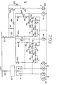
- a flasher unit 10 is connected to the movable contact of a direction indicator switch 11, fixed contacts L and R of the switch being connected respectively to left- and right-hand indicator lamps 12 of the towing vehicle.
- Each of the contacts L and R are now however also connected to the base of a transistor TR1 by way of a resistor R1, a zener diode ZD1 and a diode D4.
- Connected in parallel with the resistor R1 and the diodes ZD1 and D4 is a series circuit of two resistors R2,R3 and a diode D1, a capacitor C being connected in parallel with the resistor R2.
- a resistor R4 is connected across the base-emitter junction of the transistor TR1, while two series-connected resistors R5 and R6 are connected to the collector thereof.
- a transistor TR2 has its base coupled to the connection point between the resistors R5 and R6, while its collector-emitter path is connected in series with the left- or right-hand indicator lamps 14 of the trailer, as the case may be.
- the resistors R5 and the emitters of the transistors TR2 associated with both left- and right-hand signal operation are connected to a positive power source via a diode D3 and a fuse 21.
- a resistor R7 is connected across the diode D3, while the cathode of the diode is connected via a resistor R8 to the base of a transistor TR3 whose collector-emitter path is connected in series with a resistor R9 and a light-emitting diode 22, which takes the place of the warning lamp 19 in Figure 1.
- a zener diode ZD2 is connected across the collector- emitter path of the transistor TR3 to prevent the latter from being damaged by voltage transients, as before.
- Zener diodes ZD3, the purpose of which will be explained later, are connected between the cathode of the diode D3 and the fixed contacts L and R of the switch 11, respectively.
- Reference numeral 20 denotes a live fuse connected between the flasher unit 10 and the positive power supply, in the same manner as in the circuit of Figure 1.
- the movable contact of the direction indicator switch 11 is moved into engagement with the fixed contact L or R, according to whether a left- or a right-hand indication is to be made.
- the flasher unit 10 is then able to energise and de-energise the apppropriate indicator lamps 12 in the usual manner.
- a left-hand indication is being made, although the circuit operation for a right-hand indication will of course be exactly the same.
- the capacitor C is initially in a discharged state, but will commence charging through the resistor R3, the diode D1 and the base-emitter junction of the transistor TR1 as soon as the indicator lamps 12 are energised by the flasher unit 10.
- the indicator lamps 14 of the trailer will be cold and accordingly the resistance of their incandescent filaments will be low (about 0.2 ohms). Accordingly, the voltage drop across the lamps 14 will be small, and the diode D2 will clamp the voltage at the connection between the resistor R1 and the zener diode ZD1 at a level well below the zener voltage, so there will be no current flowing to the base of the transistor TR1 through the resistor R1.
- the charging current of the capacitor C will provide an initial pulse of base current to the transistor TR1 , thereby turning the latter on. This in turn will render the transistor TR2 conductive, so that a pulse of current is produced from the collector of the latter.
- the indicator lamps 14 will be energised by -his current pulse. As the current flows through the lamps 14, the filaments of the latter will heat up and their resistance will increase to about 7 ohms. Consequently, the voltage drop across the lamps 14 will also increase, thereby increasing the voltage at the anode of the diode D2.
- the transistor TR2 When the transistor TR2 is rendered conductive as aforesaid, current will flow through the diode D3, and the forward voltage across this diode will be sufficient to turn on the transistor TR3 by way of the resistor R8.
- the collector current of the transistor TR3 will flow via the resistor R9 to illuminate the warning LED 22, which is installed in the towing vehicle.
- the LED 22 will be energised synchronously with the indicator lamps 14.
- the diode D1 is provided to protect the base-emitter junction of the transistor TR1 from this negative voltage. The capacitor C will then commence discharging via the resistor R2.
- the capacitor C will continue to discharge as aforesaid. However, the voltage across the capacitor C will only have fallen by a relatively small amount (typically 0.8 volts) by the time the indicator lamps are energised once again.
- the magnitude and duration of the base current of transistor TR1 which is derived from the capacitor C on the second and subsequent flashes will therefore be very much less than on the first flash. This reduced current is nevertheless still sufficient to cause the voltage at the anode of the diode D2 to rise above the zener voltage of diode ZD1, because the resistance of the lamps 14 on the trailer will be higher due to the lamps still being warm from their previous energisation.
- the LED 22 will typically have a forward voltage of only about 2 volts, and the resistor R9 is provided to control the current therethrough. In the event of there being a short-circuit across the LED 22, no damage will result since the resistor R9 will limit the-current, typically to about 25 mA.
- the resistor R7 (in parallel with the diode D3) is provided to ensure that the LED22 does not come on if the current to the indicator lamps 14 is less than a certain value, say 0.6 amps, which could happen with an open-circuited lamp 14 in a corroded holder.
- the zener diodes ZD3 will cause current to flow into the base of the transistors TR1, thereby turning the transistors on. This will in turn cause the transistors TR2 to turn on and the transient will be dissipated in the indicator lamps 14. Since both of the transistors TR1 and TR2 will conduct for the duration of the transient, they will protect the entire flasher circuit from damage.
- the diodes D4 are provided to prevent the occurrence of oscillation in the circuit as the base current of the transistor TR1 falls to a level which is too low to maintain the transistor properly in conduction.
- the flasher unit 10 is of the electronic type then the voltage across the indicator lamps 12 of the towing vehicle will switch between zero and the level of the positive supply (usually 12 volts) during flashing. If however the unit 10 is of the type which incorporates a bimetallic strip, then this voltage may switch between, say, 10.5 and 3.0 volts.
- the transistor TR1 will receive base current via the resistor R1 and the zener diode ZD1, as under normal operating conditions. This is quite acceptable, since the fault resistance will then be high enough for the transistor TR2 to operate continuously without overheating. During the second and subsequent flashes, the very small charge delivered by the capacitor C into the base of the transistor TR1 will result in current pulses of only a few microseconds duration through the transistor TR2, and hence are insignificant as far as heating of the transistor TR2 is concerned.
Landscapes
- Engineering & Computer Science (AREA)
- Mechanical Engineering (AREA)
- Lighting Device Outwards From Vehicle And Optical Signal (AREA)
Applications Claiming Priority (2)
| Application Number | Priority Date | Filing Date | Title |
|---|---|---|---|
| GB8232655 | 1982-11-16 | ||
| GB8232655 | 1982-11-16 |
Publications (1)
| Publication Number | Publication Date |
|---|---|
| EP0109730A1 true EP0109730A1 (fr) | 1984-05-30 |
Family
ID=10534283
Family Applications (1)
| Application Number | Title | Priority Date | Filing Date |
|---|---|---|---|
| EP83304994A Withdrawn EP0109730A1 (fr) | 1982-11-16 | 1983-08-30 | Circuit de commande des lampes indicatrices de direction pour véhicule |
Country Status (1)
| Country | Link |
|---|---|
| EP (1) | EP0109730A1 (fr) |
Cited By (2)
| Publication number | Priority date | Publication date | Assignee | Title |
|---|---|---|---|---|
| EP1753640A2 (fr) * | 2004-05-06 | 2007-02-21 | Club Car Inc. | Systeme de commande de signal de virage pour vehicule et remorque |
| CN112004718A (zh) * | 2018-04-25 | 2020-11-27 | 株式会社小糸制作所 | 尾转向灯 |
Citations (3)
| Publication number | Priority date | Publication date | Assignee | Title |
|---|---|---|---|---|
| FR2173576A5 (fr) * | 1972-02-22 | 1973-10-05 | Westfaelische Metall Industrie | |
| FR2308523A1 (fr) * | 1975-04-22 | 1976-11-19 | Klaxon Sa | Perfectionnements aux centrales clignotantes a fil chaud a prechauffage impulsionnel |
| GB1464303A (en) * | 1975-07-22 | 1977-02-09 | G P Leisure Prod Ltd | Equipment for operating direction indicator lights on vehicle trailers |
-
1983
- 1983-08-30 EP EP83304994A patent/EP0109730A1/fr not_active Withdrawn
Patent Citations (3)
| Publication number | Priority date | Publication date | Assignee | Title |
|---|---|---|---|---|
| FR2173576A5 (fr) * | 1972-02-22 | 1973-10-05 | Westfaelische Metall Industrie | |
| FR2308523A1 (fr) * | 1975-04-22 | 1976-11-19 | Klaxon Sa | Perfectionnements aux centrales clignotantes a fil chaud a prechauffage impulsionnel |
| GB1464303A (en) * | 1975-07-22 | 1977-02-09 | G P Leisure Prod Ltd | Equipment for operating direction indicator lights on vehicle trailers |
Cited By (4)
| Publication number | Priority date | Publication date | Assignee | Title |
|---|---|---|---|---|
| EP1753640A2 (fr) * | 2004-05-06 | 2007-02-21 | Club Car Inc. | Systeme de commande de signal de virage pour vehicule et remorque |
| EP1753640A4 (fr) * | 2004-05-06 | 2009-02-25 | Club Car Inc | Systeme de commande de signal de virage pour vehicule et remorque |
| CN112004718A (zh) * | 2018-04-25 | 2020-11-27 | 株式会社小糸制作所 | 尾转向灯 |
| CN112004718B (zh) * | 2018-04-25 | 2023-08-11 | 株式会社小糸制作所 | 尾转向灯 |
Similar Documents
| Publication | Publication Date | Title |
|---|---|---|
| EP0014537B1 (fr) | Indicateur de direction pour véhicules | |
| US3522481A (en) | Storage battery protective device | |
| US4034336A (en) | Electronic monitor system for automobiles | |
| US3944969A (en) | Central warning apparatus for vehicles | |
| US5107094A (en) | Vehicle heating system with failure detection means | |
| US4447806A (en) | Test circuit for electrical continuity of a load circuit | |
| US3764879A (en) | Battery charging systems for road vehicles | |
| US3927390A (en) | Vehicle warning systems | |
| US4933665A (en) | Turn signal non-return indicator | |
| US3210727A (en) | Indicating circuits for vehicle electrical systems | |
| US3422421A (en) | Blinker type signal system with indication of defective blinker lamp | |
| EP0109730A1 (fr) | Circuit de commande des lampes indicatrices de direction pour véhicule | |
| US4320383A (en) | Fault detector for vehicle brake lights | |
| GB1570764A (en) | Circuit for monitoring electrical loads | |
| US3858088A (en) | D. c. flasher | |
| US3428943A (en) | Automobile turn signal with lamp failure indicator | |
| US4086565A (en) | Automotive electronic flasher unit | |
| EP0071366B1 (fr) | Circuit d'alimentation de lampes | |
| EP0017431A1 (fr) | Indicateur de direction pour véhicules | |
| US4107646A (en) | Centralized warning system for vehicle | |
| EP0112703B1 (fr) | Dispositif d'éclairage pour véhicule | |
| EP0009321B1 (fr) | Dispositif de commande des lampes de signalisation pour véhicule | |
| EP0005330B1 (fr) | Dispositif d'éclairage | |
| US3774188A (en) | Electrical indicating circuits | |
| US4985820A (en) | Driver circuit for switching on lamp with low cold resistance |
Legal Events
| Date | Code | Title | Description |
|---|---|---|---|
| PUAI | Public reference made under article 153(3) epc to a published international application that has entered the european phase |
Free format text: ORIGINAL CODE: 0009012 |
|
| AK | Designated contracting states |
Designated state(s): AT BE CH DE FR GB IT LI LU NL SE |
|
| STAA | Information on the status of an ep patent application or granted ep patent |
Free format text: STATUS: THE APPLICATION IS DEEMED TO BE WITHDRAWN |
|
| 18D | Application deemed to be withdrawn |
Effective date: 19850131 |
|
| RIN1 | Information on inventor provided before grant (corrected) |
Inventor name: PALMER, NORMAN HAROLD GEORGE |