EP0109466B1 - Verstellbare Konstruktion, zum Beispiel aus miteinander verbundenen Platten - Google Patents
Verstellbare Konstruktion, zum Beispiel aus miteinander verbundenen Platten Download PDFInfo
- Publication number
- EP0109466B1 EP0109466B1 EP82306224A EP82306224A EP0109466B1 EP 0109466 B1 EP0109466 B1 EP 0109466B1 EP 82306224 A EP82306224 A EP 82306224A EP 82306224 A EP82306224 A EP 82306224A EP 0109466 B1 EP0109466 B1 EP 0109466B1
- Authority
- EP
- European Patent Office
- Prior art keywords
- members
- spindle
- extrusion
- panel
- another
- Prior art date
- Legal status (The legal status is an assumption and is not a legal conclusion. Google has not performed a legal analysis and makes no representation as to the accuracy of the status listed.)
- Expired
Links
- 238000006073 displacement reaction Methods 0.000 claims abstract description 5
- 230000015572 biosynthetic process Effects 0.000 claims description 18
- 238000001125 extrusion Methods 0.000 claims description 18
- 238000005755 formation reaction Methods 0.000 claims description 18
- 230000000717 retained effect Effects 0.000 claims description 2
- 230000000295 complement effect Effects 0.000 claims 2
- 238000010276 construction Methods 0.000 abstract 1
- 238000005253 cladding Methods 0.000 description 11
- 239000004033 plastic Substances 0.000 description 7
- 229920003023 plastic Polymers 0.000 description 7
- 125000006850 spacer group Chemical group 0.000 description 7
- 229910000838 Al alloy Inorganic materials 0.000 description 2
- 239000004411 aluminium Substances 0.000 description 2
- 229910052782 aluminium Inorganic materials 0.000 description 2
- XAGFODPZIPBFFR-UHFFFAOYSA-N aluminium Chemical compound [Al] XAGFODPZIPBFFR-UHFFFAOYSA-N 0.000 description 2
- 230000004323 axial length Effects 0.000 description 2
- 238000004519 manufacturing process Methods 0.000 description 2
- 229910000831 Steel Inorganic materials 0.000 description 1
- 239000002131 composite material Substances 0.000 description 1
- 239000000945 filler Substances 0.000 description 1
- 229920002457 flexible plastic Polymers 0.000 description 1
- 239000000463 material Substances 0.000 description 1
- 229910052751 metal Inorganic materials 0.000 description 1
- 239000002184 metal Substances 0.000 description 1
- 239000002991 molded plastic Substances 0.000 description 1
- 238000000926 separation method Methods 0.000 description 1
- 239000010959 steel Substances 0.000 description 1
Images
Classifications
-
- E—FIXED CONSTRUCTIONS
- E05—LOCKS; KEYS; WINDOW OR DOOR FITTINGS; SAFES
- E05D—HINGES OR SUSPENSION DEVICES FOR DOORS, WINDOWS OR WINGS
- E05D3/00—Hinges with pins
- E05D3/06—Hinges with pins with two or more pins
- E05D3/12—Hinges with pins with two or more pins with two parallel pins and one arm
- E05D3/122—Gear hinges
-
- E—FIXED CONSTRUCTIONS
- E04—BUILDING
- E04B—GENERAL BUILDING CONSTRUCTIONS; WALLS, e.g. PARTITIONS; ROOFS; FLOORS; CEILINGS; INSULATION OR OTHER PROTECTION OF BUILDINGS
- E04B2/00—Walls, e.g. partitions, for buildings; Wall construction with regard to insulation; Connections specially adapted to walls
- E04B2/74—Removable non-load-bearing partitions; Partitions with a free upper edge
- E04B2/7407—Removable non-load-bearing partitions; Partitions with a free upper edge assembled using frames with infill panels or coverings only; made-up of panels and a support structure incorporating posts
- E04B2/7416—Removable non-load-bearing partitions; Partitions with a free upper edge assembled using frames with infill panels or coverings only; made-up of panels and a support structure incorporating posts with free upper edge, e.g. for use as office space dividers
- E04B2/7422—Removable non-load-bearing partitions; Partitions with a free upper edge assembled using frames with infill panels or coverings only; made-up of panels and a support structure incorporating posts with free upper edge, e.g. for use as office space dividers with separate framed panels without intermediary support posts
- E04B2/7427—Removable non-load-bearing partitions; Partitions with a free upper edge assembled using frames with infill panels or coverings only; made-up of panels and a support structure incorporating posts with free upper edge, e.g. for use as office space dividers with separate framed panels without intermediary support posts with adjustable angular connection of panels
- E04B2/7431—Removable non-load-bearing partitions; Partitions with a free upper edge assembled using frames with infill panels or coverings only; made-up of panels and a support structure incorporating posts with free upper edge, e.g. for use as office space dividers with separate framed panels without intermediary support posts with adjustable angular connection of panels using hinges having two parallel rotation axes
-
- E—FIXED CONSTRUCTIONS
- E05—LOCKS; KEYS; WINDOW OR DOOR FITTINGS; SAFES
- E05Y—INDEXING SCHEME ASSOCIATED WITH SUBCLASSES E05D AND E05F, RELATING TO CONSTRUCTION ELEMENTS, ELECTRIC CONTROL, POWER SUPPLY, POWER SIGNAL OR TRANSMISSION, USER INTERFACES, MOUNTING OR COUPLING, DETAILS, ACCESSORIES, AUXILIARY OPERATIONS NOT OTHERWISE PROVIDED FOR, APPLICATION THEREOF
- E05Y2999/00—Subject-matter not otherwise provided for in this subclass
Definitions
- This invention relates to an adjustable structure comprising two members each having ribs and grooves interengaging with one another after the fashion of gear teeth.
- a structure of this general type is known, for example from our British Patent Specification No. 1,542,244 which discloses a structure in the form of a series of hingedly interconnected panels intended as a temporary display structure for exhibition and the like purposes.
- an adjustable structure comprising two members each having ribs and grooves interengaging with one another after the fashion of gearteeth so that the members can roll relative to one another about respective axes, characterised by each said member carrying a resilient spindle element disposed substantially coaxially with the respective said member and resiliently displaceable, at least in part, transversely of said axis, said members being held together by at least one connecting element providing openings or recesses receiving respective said resilient spindle elements of the two members, the configuration of the connecting element and/or the spindle elements being such that resilient displacement of said spindle elements transversely of said axes, towards one another is necessary to apply the connecting element to or detach it from said spindle elements.
- the drawings relate to systems of hingedly interconnected panels, for use in temporary exhibition displays and the like, in which the connection between adjoining edges of adjoining panels is effected by means of gearlike members secured to the respective edges of the respective panels and meshing with one another, so that the panels are connected together in such a manner as to allow smooth controlled adjustment movements to be effected between panels, and so that the panels may be folded together accordian fashion, etc.
- the general arrangement of interconnected panels and adjustment of the panels relative to one another is substantially the same as that described in our British Patent Specification No. 1,542,244 to which reference should be had.
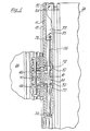
- the gear-like members secured to the adjoining edges of adjoining panels are of composite form each comprising a member 11 consisting of a length cut from an extrusion of the uniform cross section discernable from Figure 2, which extrusion may be an extrusion in aluminium alloy and fitted to member 11, cladding members 13, e.g. of plastics, of the cross-section shown.
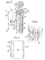
- the extrusion which affords each member 11 comprises a part 12 which has the approximate form of a capital "D" with one of the two "corners” removed to provide a longitudinally extending slot along the section, which facilitates the manufacture, by extrusion, of the member 11, said slot communicating with the central passage 33 along the part 12 and which passage, but for said slot, is cylindrical in section.
- the part or portion 12 corresponding to the straight part of the "D" adjoins, and is integral with, a web 16, of greater transverse width than portion 12 and which thus projects beyond portion 12 on either side.
- the web 16 is connected via a perpendicular central web 18 with an attachment part, indicated generally at 20, which provides a flat rear face, parallel with the web 16, which is secured to the planar edge face 22 of the respective panel 24.
- the part 20 is formed with a generally T-shaped longitudinal channel which opens in a longitudinal central slot 26 on the rear face of part 20 and the part 20 is secured to the panel 24 by screws 28 the heads of which are held captive in the wider part of the T-section channel and the shanks of which pass through the slot 26 into the edge face 22 of the panel.
- the heads of the screws 28 pass through circular enlargements 30 formed at predetermined positions along the slot 26, to enter the T-section channel, and the member 11 is then displaced longitudinally into its final position, so that the enlargements 30 are moved out of register with the heads of the screws 28 and the screw's heads are held captive in the T-shaped channel.
- the manner of attachment is thus analogous to a "key-hole slot" arrangement.
- Extended filler strips may cover the channels 17 when these are not required.
- each cladding member 13 affords longitudinally extending ribs 14, which form the gear teeth and between which are defined the grooves which receive the gear teeth of the co-operating cladding member.
- each .member 11 Located within the central passage 33 ( Figure 2) in each .member 11 are a plurality of spindle elements, of the form shown in side elevation at 35 in Figure 1, and each comprising a resilient steel rod 36, fitted at one end with a resilient plastics cap 38 and fitted at its other end with a metal disc 39 with a "milled" periphery affording longitudinally extending grooves between which teeth are defined, the rod 36 being provided midway between its ends with a tubular plastics spacer 41.
- Each cap 38 is dimensioned to fit closely within passage 33, when the element 34 is fitted within the passage 33 whilst the disc 39 is so formed and dimensioned, with a slight taper towards the cap 38, that it is slightly oversize in relation to the passage 33 and must be driven forcibly into position along the passage 33 while the teeth thereon bite into the wall of the passage to hold the disc 39, and thus the rod 36, in place.
- the slots 32 are formed in pairs, with the axial spacing between the slots of a pair being greater than the axial length of the spacer 41 and each element 35 is disposed with its spacer 41 located within a respective portion 44 of the member 11 lying between the two slots 32 of a respective said pair.
- the external diameter of the spacers 41 is somewhat less than that of the caps 38, so that the spacers 41 have a predetermined transverse clearance in the passage 33.
- each connecting link 46 is in the form of a plate or bar having parallel upper and lower faces and affording at either end thereof a respective hook formation 47 which engages around the rod 36 of the respective element 34.
- each hook formation 47 has a free end which extends further, in the direction towards the other hook formation 47 than the deepest part of the recess formed within the bend of the hook formation, and the arrangement is such that the inherent resilience of the rods 36 engaged by each link 46 urges the rods 36 apart to a spacing which is greater than the spacing between the closest part of the free ends of the two hook formations of the link.
- the surfaces of the hook formations 47 in the region of the parts of the free ends of the hook formations which are closest to one another are formed as cam surfaces, so that any link 46 may be removed simply by pushing it, in the direction indicated by the arrow C in Figure 3B, so that by the camming action between the hook formation 47 and the rods 36 the latter are urged resiliently towards one another to the extent necessary to allow the rods 36 to pass from the connecting link.
- the link can be refitted simply by pushing it into the aligned slots 32 in the direction indicated by the arrow D in Figure 3B so that the camming surfaces on the free ends of the hook formations 47 urge the rods 36 together resiliently sufficiently to allow the rods to enter the recesses within the hook formations 47.
- the amount of transverse flexing which the rods 36 may undergo is limited by engagement of the spacers 41 with the walls of the passages 33.
- the cladding of a member 11 above and below a respective pair of slots 32 is formed by respective lengths of an extrusion of the cross-section shown, which is in the form of a generally channel-shaped body which has, externally, the desired geared profile and has, internally, formations to co-operate with corresponding external formations on portion 12, including a median groove to receive a median locating rib on the portion 12 and respective saw-tooth section formations adjacent the edges of the channel, for engagement behind an abutment provided by one edge of the longitudinal slot in portion 12 and behind an abutment provided, on the opposite side of the portion 12, by a saw-tooth section formation on portion 12, so that the cladding 13 may be snap-fitted on portion 12 to be thereafter retained thereon.
- the cladding of member 11 between the two slots of one such pair of slots is formed as an injection-moulded plastics member 70 which has, intermediate its upper and lower ends the same cross-sectional shape as the extruded cladding, but has its upper and lower ends formed to provide formations extending across the ends of the respective section of portion 12 between the slots, to conceal said ends and yet afford a passage for the rod 36 (see Figure 1).
- the adjoining ends of the portion 12 above and below the respective pair of slots, i.e. the ends which face the member 70, are covered by end plugs 72, of arcuate form, fitted in the passage 33 and having flanges extending over the respective ends of the portion 12 and the extruded cladding.
- Each link is thus located at each end between a member 70 and an adjoining end plug 72.
- a respective further plastics insert 54 may be provided of the form shown in Figures 1 and 2 and comprising a cap for the respective end of the portion 12 and a cover for the respective end of the part 20, with, on its underside, projections for engagement in the passage 33 and the T-shaped channel.
- the insert 54 has a central aperture 55 aligned with the central passage 33, through which, for example, a supporting rod (not shown) of an ancillary fitting may be extended or through which an electrical flex may be extended.
- each panel may have, spaced apart along the axial length of each of the two members 11, 13, secured to respective opposite longitudinal edges of the panel, three pairs of slots 32, each pair of slots 32 having associated therewith a respective element 35 accommodated within the respective member 11, 13, with each panel being connected with the adjoining panel, (i.e. each member 11, 13, with the adjoining member 11,13), by three pairs of connecting links 46, each connecting link 46 being engaged in a respective slot 32 of one member 10 and the aligned slots 32 of the adjoining, meshing member 11, 13.
- the axes of the rods 36 inserted in the passage 33 of any one member 11 are preferably substantially coincident with the axis of the pitch circle of the "gear-segment" defined by the corresponding members 13, so that the panels may be readily and smoothly pivoted relative to one another as desired.
- the resilience of the rods 36 of course permits slight resilient relative transverse displacement between meshing members 13, which thus compensates for inaccuracies of the gear form of the ribs 14.
- An advantage which is afforded by disposing the slots 32 in pairs is that this also makes it possible, if desired, to connect first and second gear members 11, 13, at the edges of respective panels with a third gear member 11, 13, at the edge of a further panel, with the third gear member meshing with both the second and third gear members 11, 13, and one slot of each pair of slots 32 in the third gear member being occupied by a link 46 connecting the third gear member with the first gear member 11, 13, and with the other slot in the third gear member being occupied by a link 46 connecting the third gear member 11, 13, with the second gear member 11, 13.
- the first or second gear member might likewise be connected with a yet further, meshing gear member 11, 13, and so on, so that, for example structures in which a plurality of panels radiate from a common junction region may be readily constructed.
- the ribs or teeth 14 may be formed integrally with the remainder of the aluminium extrusion.
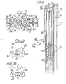
- the gear- like members, indicated at 10 in Figure 5, secured to the adjoining edges of adjoining panels may be formed by lengths cut from an extrusion, e.g. of aluminium alloy, of the uniform cross-section discernable from Figure 5.
- the extrusion affording member 10 corresponds, in cross-sectional shape to that affording member 11, except that in place of the portion 12 an arcuate portion 121 is provided, of larger radius than portion 12 and which extends from one edge of web 16 to the other, the web 16 thus forming the back of an enlarged "D".
- the portion 121 is provided externally with the longitudinally extending ribs 14, which form the gear teeth and between which are defined the grooves which receive the gear teeth of the co-operating member 10.
- the extrusion from which member 10 is cut may, if desired, be plastics coated.
- each slot 32 is fitted with a plastics insert 50 comprising two horseshoe-shaped pieces connected to one another, at the free ends of their limbs, by respective flexible plastics webs 51.
- Each horseshoe-shaped piece has, on its side remote from the other piece, a flat abutment face for engagement with the respective edge face of the respective slot 32 and has, upstanding from this flat abutment face, one or more projections for engagement with the interior of the arcuate wall of the part 12.
- the insert 50 by reason of the flexibility of the plastics material, may be temporarily deformed to allow the insert to be inserted in the respective slots 32 and the projections on the abutment faces engaged with the interior of the passage 33, so that the insert effectively affords a lining for the upper and lower edges of the slot.
- Such an insert 50 is shown already fitted in a slot 32 in Figure 6.
- the free width of the slot corresponds to the separation between the opposing pieces of the insert and is slightly greater than the thickness of the connecting link 46.
- the two pieces of each insert 50 are provided, on their convex outer edges with teeth which, when the inserts are fitted, form extensions of the ribs 14 of the respective member 10.
- the edges of each insert which oppose each other when the insert is fitted are rounded as viewed in axial section.
- the inserts 50 besides affording a finished appearance, also serve as bearing members for the connecting links 46 and, furthermore, serve to limit axial movement of the spacers 41.
Landscapes
- Engineering & Computer Science (AREA)
- Architecture (AREA)
- Structural Engineering (AREA)
- Physics & Mathematics (AREA)
- Electromagnetism (AREA)
- Civil Engineering (AREA)
- Mechanical Engineering (AREA)
- Mutual Connection Of Rods And Tubes (AREA)
- Joining Of Building Structures In Genera (AREA)
- Rod-Shaped Construction Members (AREA)
- Extrusion Moulding Of Plastics Or The Like (AREA)
- Connection Of Plates (AREA)
- Preliminary Treatment Of Fibers (AREA)
Claims (7)
Priority Applications (4)
| Application Number | Priority Date | Filing Date | Title |
|---|---|---|---|
| DE8282306224T DE3271205D1 (en) | 1982-11-23 | 1982-11-23 | Adjustable structure, for example, comprising interconnected panels |
| EP82306224A EP0109466B1 (de) | 1982-11-23 | 1982-11-23 | Verstellbare Konstruktion, zum Beispiel aus miteinander verbundenen Platten |
| DE198282306224T DE109466T1 (de) | 1982-11-23 | 1982-11-23 | Verstellbare konstruktion, zum beispiel aus miteinander verbundenen platten. |
| AT82306224T ATE19804T1 (de) | 1982-11-23 | 1982-11-23 | Verstellbare konstruktion, zum beispiel aus miteinander verbundenen platten. |
Applications Claiming Priority (1)
| Application Number | Priority Date | Filing Date | Title |
|---|---|---|---|
| EP82306224A EP0109466B1 (de) | 1982-11-23 | 1982-11-23 | Verstellbare Konstruktion, zum Beispiel aus miteinander verbundenen Platten |
Publications (2)
| Publication Number | Publication Date |
|---|---|
| EP0109466A1 EP0109466A1 (de) | 1984-05-30 |
| EP0109466B1 true EP0109466B1 (de) | 1986-05-14 |
Family
ID=8189839
Family Applications (1)
| Application Number | Title | Priority Date | Filing Date |
|---|---|---|---|
| EP82306224A Expired EP0109466B1 (de) | 1982-11-23 | 1982-11-23 | Verstellbare Konstruktion, zum Beispiel aus miteinander verbundenen Platten |
Country Status (3)
| Country | Link |
|---|---|
| EP (1) | EP0109466B1 (de) |
| AT (1) | ATE19804T1 (de) |
| DE (2) | DE109466T1 (de) |
Families Citing this family (9)
| Publication number | Priority date | Publication date | Assignee | Title |
|---|---|---|---|---|
| SE455827B (sv) * | 1986-12-01 | 1988-08-08 | Hallengren Ulf | Vikledselement |
| SE459512B (sv) * | 1986-09-18 | 1989-07-10 | Bjoern Lindberg | Gaangjaernsled och utstaellningssystem utnyttjande naemnda gaangjaernsled |
| FR2612981A1 (fr) * | 1987-03-27 | 1988-09-30 | Socamel Sa | Charniere a double effet et a grande amplitude de debattement |
| DE68910979T2 (de) * | 1988-08-08 | 1994-06-09 | Upham Hill Christopher William | Verbindungssystem. |
| SE467218B (sv) * | 1990-02-14 | 1992-06-15 | Erik Ahlberg | Led |
| DE9200642U1 (de) * | 1992-01-21 | 1993-05-19 | Pies, Gerrit, 5650 Solingen | Verbindung von Profilstäben |
| SE504505C2 (sv) * | 1994-10-18 | 1997-02-24 | Kinnarps Ab | Skärmvägg |
| GB9501792D0 (en) * | 1995-01-25 | 1995-03-22 | Marler Haley Exposystems Ltd | "Panel connector arrangement" |
| GB2418454B (en) * | 2004-09-22 | 2009-04-15 | Mark Edward Bushdyhan | Hinge assembly |
Citations (1)
| Publication number | Priority date | Publication date | Assignee | Title |
|---|---|---|---|---|
| GB1542244A (en) * | 1974-10-17 | 1979-03-14 | Marler Haley Exposystems Ltd | Panel systems |
Family Cites Families (2)
| Publication number | Priority date | Publication date | Assignee | Title |
|---|---|---|---|---|
| US3374499A (en) * | 1966-09-12 | 1968-03-26 | Mckinney Mfg Co | Hinge with a pair of parallel pivots |
| IT1127795B (it) * | 1979-09-19 | 1986-05-21 | Afra Bianchin Scarpa | Giuto d'articolazione per pannelli verticali sospesi |
-
1982
- 1982-11-23 EP EP82306224A patent/EP0109466B1/de not_active Expired
- 1982-11-23 AT AT82306224T patent/ATE19804T1/de not_active IP Right Cessation
- 1982-11-23 DE DE198282306224T patent/DE109466T1/de active Pending
- 1982-11-23 DE DE8282306224T patent/DE3271205D1/de not_active Expired
Patent Citations (1)
| Publication number | Priority date | Publication date | Assignee | Title |
|---|---|---|---|---|
| GB1542244A (en) * | 1974-10-17 | 1979-03-14 | Marler Haley Exposystems Ltd | Panel systems |
Also Published As
| Publication number | Publication date |
|---|---|
| DE3271205D1 (en) | 1986-06-19 |
| ATE19804T1 (de) | 1986-05-15 |
| EP0109466A1 (de) | 1984-05-30 |
| DE109466T1 (de) | 1985-01-31 |
Similar Documents
| Publication | Publication Date | Title |
|---|---|---|
| US4443911A (en) | Device for interconnecting panels | |
| EP0109466B1 (de) | Verstellbare Konstruktion, zum Beispiel aus miteinander verbundenen Platten | |
| CA1091887A (en) | Panel assemblies and components | |
| CA1107028A (en) | Demountable interior partition system, components therefor, and method of making such components | |
| GB2106176A (en) | Adjustable structure, for example, comprising interconnected panels | |
| DE69313401T2 (de) | Kabel Halterungs und Aufnahmevorrichtung in einen Kabelkanal | |
| US4999879A (en) | Pinless hinge structure with gear portions | |
| US4235049A (en) | Edge fitting assembly for a panel | |
| GB2141462A (en) | Screw slot runner system | |
| GB2117158A (en) | Frame for use in a portable display system | |
| GB2191518A (en) | Cornice system with covered joints | |
| US6027192A (en) | Molded panels for cabinets | |
| GB2189290A (en) | Connecting means for panels | |
| EP0342151A1 (de) | Kasten, insbesondere Badezimmerschrank | |
| US4893446A (en) | Relocatable vertical or horizontal wall system | |
| US6820306B2 (en) | Side wheel assembly of curtain track | |
| CA1207528A (en) | Adjustable structure, for example, comprising interconnected panels | |
| US3331095A (en) | Curtain rail, preferably of synthetic plastic material, having curved end sections | |
| EP1002166B1 (de) | Trennwandung, insbesondere für messe- und ausstellungsstände | |
| EP0169697B1 (de) | Verbindungsanordnung | |
| GB2157336A (en) | Partitions | |
| DE68907242T2 (de) | Kantenstreifen für Platten. | |
| EP0521076A1 (de) | Kassettenarchiv | |
| DE19646541C1 (de) | Bausatz miteinander verbindbarer Profilelemente | |
| EP1049227B1 (de) | Verteilungsschienen mit Berührungsschutz |
Legal Events
| Date | Code | Title | Description |
|---|---|---|---|
| PUAI | Public reference made under article 153(3) epc to a published international application that has entered the european phase |
Free format text: ORIGINAL CODE: 0009012 |
|
| AK | Designated contracting states |
Designated state(s): AT BE CH DE FR GB IT LI LU NL SE |
|
| 17P | Request for examination filed |
Effective date: 19841008 |
|
| DET | De: translation of patent claims | ||
| TCAT | At: translation of patent claims filed | ||
| EL | Fr: translation of claims filed | ||
| TCNL | Nl: translation of patent claims filed | ||
| ITF | It: translation for a ep patent filed | ||
| RBV | Designated contracting states (corrected) |
Designated state(s): AT BE CH DE FR IT LI LU NL SE |
|
| GRAA | (expected) grant |
Free format text: ORIGINAL CODE: 0009210 |
|
| AK | Designated contracting states |
Kind code of ref document: B1 Designated state(s): AT BE CH DE FR IT LI LU NL SE |
|
| REF | Corresponds to: |
Ref document number: 19804 Country of ref document: AT Date of ref document: 19860515 Kind code of ref document: T |
|
| REF | Corresponds to: |
Ref document number: 3271205 Country of ref document: DE Date of ref document: 19860619 |
|
| ET | Fr: translation filed | ||
| PLBE | No opposition filed within time limit |
Free format text: ORIGINAL CODE: 0009261 |
|
| STAA | Information on the status of an ep patent application or granted ep patent |
Free format text: STATUS: NO OPPOSITION FILED WITHIN TIME LIMIT |
|
| 26N | No opposition filed | ||
| ITTA | It: last paid annual fee | ||
| PGFP | Annual fee paid to national office [announced via postgrant information from national office to epo] |
Ref country code: AT Payment date: 19921019 Year of fee payment: 11 |
|
| PGFP | Annual fee paid to national office [announced via postgrant information from national office to epo] |
Ref country code: FR Payment date: 19921109 Year of fee payment: 11 |
|
| PGFP | Annual fee paid to national office [announced via postgrant information from national office to epo] |
Ref country code: SE Payment date: 19921116 Year of fee payment: 11 |
|
| PGFP | Annual fee paid to national office [announced via postgrant information from national office to epo] |
Ref country code: CH Payment date: 19921125 Year of fee payment: 11 |
|
| PGFP | Annual fee paid to national office [announced via postgrant information from national office to epo] |
Ref country code: NL Payment date: 19921130 Year of fee payment: 11 |
|
| PGFP | Annual fee paid to national office [announced via postgrant information from national office to epo] |
Ref country code: LU Payment date: 19921210 Year of fee payment: 11 |
|
| PGFP | Annual fee paid to national office [announced via postgrant information from national office to epo] |
Ref country code: DE Payment date: 19921212 Year of fee payment: 11 |
|
| PGFP | Annual fee paid to national office [announced via postgrant information from national office to epo] |
Ref country code: BE Payment date: 19921223 Year of fee payment: 11 |
|
| EPTA | Lu: last paid annual fee | ||
| PG25 | Lapsed in a contracting state [announced via postgrant information from national office to epo] |
Ref country code: LU Free format text: LAPSE BECAUSE OF NON-PAYMENT OF DUE FEES Effective date: 19931123 Ref country code: AT Effective date: 19931123 |
|
| PG25 | Lapsed in a contracting state [announced via postgrant information from national office to epo] |
Ref country code: SE Effective date: 19931124 |
|
| PG25 | Lapsed in a contracting state [announced via postgrant information from national office to epo] |
Ref country code: LI Effective date: 19931130 Ref country code: CH Effective date: 19931130 Ref country code: BE Effective date: 19931130 |
|
| BERE | Be: lapsed |
Owner name: MARLER HALEY EXPOSYSTEMS LTD Effective date: 19931130 |
|
| PG25 | Lapsed in a contracting state [announced via postgrant information from national office to epo] |
Ref country code: NL Effective date: 19940601 |
|
| NLV4 | Nl: lapsed or anulled due to non-payment of the annual fee | ||
| PG25 | Lapsed in a contracting state [announced via postgrant information from national office to epo] |
Ref country code: FR Effective date: 19940729 |
|
| REG | Reference to a national code |
Ref country code: CH Ref legal event code: PL |
|
| PG25 | Lapsed in a contracting state [announced via postgrant information from national office to epo] |
Ref country code: DE Effective date: 19940802 |
|
| REG | Reference to a national code |
Ref country code: FR Ref legal event code: ST |
|
| EUG | Se: european patent has lapsed |
Ref document number: 82306224.5 Effective date: 19940610 |