EP0108690B1 - Echangeur de chaleur pour fluides à température élevée dont l'un des fluides entre et sort par la partie supérieure de l'échangeur - Google Patents
Echangeur de chaleur pour fluides à température élevée dont l'un des fluides entre et sort par la partie supérieure de l'échangeur Download PDFInfo
- Publication number
- EP0108690B1 EP0108690B1 EP83402128A EP83402128A EP0108690B1 EP 0108690 B1 EP0108690 B1 EP 0108690B1 EP 83402128 A EP83402128 A EP 83402128A EP 83402128 A EP83402128 A EP 83402128A EP 0108690 B1 EP0108690 B1 EP 0108690B1
- Authority
- EP
- European Patent Office
- Prior art keywords
- exchanger
- bundle
- tube plate
- shell
- fluid
- Prior art date
- Legal status (The legal status is an assumption and is not a legal conclusion. Google has not performed a legal analysis and makes no representation as to the accuracy of the status listed.)
- Expired
Links
- 239000012530 fluid Substances 0.000 title claims description 29
- 239000007789 gas Substances 0.000 claims description 14
- 239000011261 inert gas Substances 0.000 claims 3
- DGAQECJNVWCQMB-PUAWFVPOSA-M Ilexoside XXIX Chemical compound C[C@@H]1CC[C@@]2(CC[C@@]3(C(=CC[C@H]4[C@]3(CC[C@@H]5[C@@]4(CC[C@@H](C5(C)C)OS(=O)(=O)[O-])C)C)[C@@H]2[C@]1(C)O)C)C(=O)O[C@H]6[C@@H]([C@H]([C@@H]([C@H](O6)CO)O)O)O.[Na+] DGAQECJNVWCQMB-PUAWFVPOSA-M 0.000 description 44
- 229910052708 sodium Inorganic materials 0.000 description 44
- 239000011734 sodium Substances 0.000 description 44
- 230000007935 neutral effect Effects 0.000 description 10
- XKRFYHLGVUSROY-UHFFFAOYSA-N Argon Chemical compound [Ar] XKRFYHLGVUSROY-UHFFFAOYSA-N 0.000 description 4
- 239000007788 liquid Substances 0.000 description 4
- 238000009413 insulation Methods 0.000 description 3
- 229910052786 argon Inorganic materials 0.000 description 2
- 230000001105 regulatory effect Effects 0.000 description 2
- 238000000926 separation method Methods 0.000 description 1
- 238000003466 welding Methods 0.000 description 1
Images
Classifications
-
- F—MECHANICAL ENGINEERING; LIGHTING; HEATING; WEAPONS; BLASTING
- F28—HEAT EXCHANGE IN GENERAL
- F28D—HEAT-EXCHANGE APPARATUS, NOT PROVIDED FOR IN ANOTHER SUBCLASS, IN WHICH THE HEAT-EXCHANGE MEDIA DO NOT COME INTO DIRECT CONTACT
- F28D1/00—Heat-exchange apparatus having stationary conduit assemblies for one heat-exchange medium only, the media being in contact with different sides of the conduit wall, in which the other heat-exchange medium is a large body of fluid, e.g. domestic or motor car radiators
- F28D1/02—Heat-exchange apparatus having stationary conduit assemblies for one heat-exchange medium only, the media being in contact with different sides of the conduit wall, in which the other heat-exchange medium is a large body of fluid, e.g. domestic or motor car radiators with heat-exchange conduits immersed in the body of fluid
- F28D1/0206—Heat exchangers immersed in a large body of liquid
- F28D1/0213—Heat exchangers immersed in a large body of liquid for heating or cooling a liquid in a tank
-
- F—MECHANICAL ENGINEERING; LIGHTING; HEATING; WEAPONS; BLASTING
- F28—HEAT EXCHANGE IN GENERAL
- F28D—HEAT-EXCHANGE APPARATUS, NOT PROVIDED FOR IN ANOTHER SUBCLASS, IN WHICH THE HEAT-EXCHANGE MEDIA DO NOT COME INTO DIRECT CONTACT
- F28D21/00—Heat-exchange apparatus not covered by any of the groups F28D1/00 - F28D20/00
- F28D2021/0019—Other heat exchangers for particular applications; Heat exchange systems not otherwise provided for
- F28D2021/0054—Other heat exchangers for particular applications; Heat exchange systems not otherwise provided for for nuclear applications
Definitions
- the invention relates to a heat exchanger with two fluids, one of the fluids of which enters the exchanger and exits from this exchanger through its upper part, as known from EP-A-0012691.
- Such exchangers are used, for example, in integrated-type fast neutron nuclear reactors where the heat released by the reactor core is removed using primary sodium contained in the reactor vessel and into which the core of the reactor is immersed. reactor.
- the heat is transmitted to the steam generator via secondary sodium which is heated by the primary sodium in heat exchangers immersed in the primary sodium filling the tank called intermediate heat exchangers.
- Secondary sodium enters these intermediate exchangers through their upper part, above the slab closing the reactor vessel, and must likewise exit from the intermediate heat exchanger through its upper part, above the slab.
- Such heat exchangers comprise a tubular bundle of annular shape and with vertical straight tubes in which the secondary sodium is caused to flow from bottom to top.
- the tube bundle has two annular tube plates at its lower part and at its upper part respectively.
- the secondary sodium is brought under the lower tubular plate to be circulated in the tubes of the bundle, by a central vertical duct crossing the exchanger over its entire height and connected at its upper part to a secondary sodium inlet duct.
- the secondary sodium enters an annular duct arranged coaxially with respect to the inlet duct of the secondary sodium and also opening at the upper part of the exchanger.
- the tube bundle is immersed in the primary sodium which is circulated in contact with the outside surface of the tubes of the bundle by means of circulation pumps immersed in the primary sodium contained in the reactor vessel.
- the secondary sodium supply conduit under the lower plate of the tube bundle is constituted by a cylindrical double wall with a vertical axis also constituting the internal wall of the tube bundle.
- This cylindrical double wall is constituted by a first ferrule welded to the two tubular plates of the bundle, along their internal edges and extended upwards to the upper level of the exchanger and by a second cylindrical ferrule coaxial with the first fixed to the lower plate of the tube bundle along its internal edge and connected at its upper part to the secondary sodium inlet duct.
- This second ferrule is disposed inside the first, the two ferrules being connected at their upper part by a tight expansion joint making it possible to establish a gaseous atmosphere of thermal insulation (for example argon) in the annular space between the two ferrules constituting the internal wall of the tube bundle and the secondary sodium inlet duct.
- This gaseous layer also makes it possible to thermally isolate the secondary sodium entering the heat exchanger from the heated secondary sodium leaving the tube bundle.
- the outer shell of the secondary sodium supply duct which is welded to both the lower tube plate and the upper tube plate of the bundle is very highly stressed.
- the assembly formed by this ferrule, the bundle tubes and the tubular plates is in fact one-piece and hyperstatic.
- the different elements for example the ferrule and the tubes of the bundle, have very different rigidities.
- the heat exchanger therefore undergoes significant differential expansion and deformation in its central part comprising the internal wall of the tube bundle.
- the object of the invention is therefore to propose a heat exchanger for fluids at elevated temperature one of which, or first fluid, enters the exchanger at its upper part, circulates from bottom to top inside the exchanger in the straight vertical tubes of a ring-shaped bundle with a vertical axis comprising a lower tubular plate and an annular upper tubular plate as well as a central cylindrical internal wall coaxial with the bundle, serving as a conduit for the first fluid under the lower tubular plate and finally, leaves the exchanger at its upper part, via an annular outlet duct coaxial with the fluid supply duct and thermally insulated from it, the second fluid circulating in contact with the external surface of the tubes of the bundle, this heat exchanger not undergoing excessive thermal or mechanical stresses, in its central part comprising the internal wall of the tubular bundle.
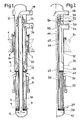
- Figure 1 shows, in a sectional view through a vertical plane, an intermediate heat exchanger according to the prior art.
- FIG. 2 represents, in a half-view in section through a vertical plane of symmetry, a heat exchanger according to the invention.
- the lower part of the exchanger comprising a tubular bundle 5 plunges under the upper level 4 of the liquid sodium filling the tank and constituting the primary fluid of the reactor.
- This primary fluid is circulated by pumps plunging into the tank so that it enters through the inlet window 6 of the heat exchanger, at its outlet from the core.
- the primary sodium circulates in contact with the tubes of the bundle 5 to exit through the outlet window 7 of the heat exchanger. Between the windows 6 and 7, the tubular bundle is surrounded by a cylindrical envelope 8.
- the tube bundle comprises two tube plates, a lower tube plate 9 and an upper tube plate 10.
- a secondary sodium inlet chamber 12 into which the sodium 14 feed duct opens.
- the duct 14 consists of a double wall formed by two vertical coaxial ferrules 15 and 16.
- the outer shell 15 of this wall is fixed by welding to the lower plate 9 and to the upper plate 10 of the tube bundle.
- the secondary sodium heated by the primary sodium enters an annular outlet conduit 20 coaxial with the ferrules 15 and 16.
- the outer ferrule of the conduit 20 is connected at its upper part to the ferrules 15 and 16 by l 'through expansion joints 21 and 22.
- annular chamber is delimited by the ferrules 15 and 16 and this annular chamber is filled with a neutral gas ensuring thermal insulation between the cold secondary sodium arriving via the conduit 14 and the hot secondary sodium leaving via the annular conduit 20.
- the conduit 20 is connected to a pipe 24 bringing the hot sodium to the steam generator.
- the assembly formed by the plates 9 and 10, the tubular exchanger 5 and the internal ferrule 15 thereof is extremely rigid, the straight tubes of the bundle being welded to the tubular plates 9 and 10 and the ferrule 15 being welded to these two tubular plates 9 and 10.
- This high rigidity is due in particular to the fact that the bundle tubes are straight and numerous.
- the lower part of the heat exchanger immersed in the primary liquid sodium comprises a tube bundle 35, the primary liquid sodium circulating between the inlet window 36 and the outlet window 37 of the heat exchanger in contact with the surface beam tubes. 35.
- the tubes of this bundle arranged vertically are straight and fixed at their lower end in a tubular plate 39 and at their upper part in a tubular plate 40.
- a chamber 42 into which the cold secondary sodium arrives and serving for its distribution in the tubes of the bundle 35.
- the cold secondary sodium is brought into the chamber 42 by a vertical central duct 44 which limits the internal part of the tubular bundle 35 and by its extension.
- This wall consists of three vertical and coaxial cylindrical ferrules.
- the first innermost ferrule 45 is welded by its lower edge along the internal edge of the annular lower tubular plate 39.
- the upper part of the ferrule 45 is connected to a conduit 48 for the secondary sodium, constituting the first fluid, in the heat exchanger.
- the second ferrule 46 disposed outside of the ferrule 45 is welded by its lower edge to the lower tubular plate 39 and its upper part is at the level of the upper part of the heat exchanger.
- the ferrules 45 and 46 are sold only on the lower tube plate 39.
- the third ferrule 47 is welded to the upper tube plate 40, along the inner edge of this tube plate. This ferrule 47 is extended downward to a level located between the two tubular plates 39 and 40, in the vicinity of the middle part of the tubular bundle 35. The upper part of the third ferrule 47 is at the level of the upper part of the heat exchanger.
- the ferrule 47 is connected by a gas tight expansion joint 50 to the upper part of the ferrule 45. This ferrule 47 is also connected by a gas tight expansion joint 52 to the upper part of the second ferrule 46.
- the secondary sodium constituting the first fluid in circulation in the heat exchanger, enters an annular conduit 60 coaxial with the ferrules 45, 46 and 47 connected at its upper part to a conduit 64 towards the steam generator.
- the secondary sodium heated by the primary sodium constituting the second fluid of the exchanger is isolated in the conduit 60 from the cold secondary sodium arriving via the central part of the exchanger in the chamber 42, by a double gaseous layer.
- annular gas-tight chamber 54 between the ferrules 45 and 46 the annular chamber 55 between the ferrules 46 and 47 are filled with neutral gas, over the entire length of the conduit 60.
- the neutral gas filling the chamber 54 is introduced into this chamber where it remains trapped after closing the flexible seal 50.
- the chamber 55 is connected at its upper part to a circuit 56 for supplying neutral gas at a regulated pressure.
- the lower part of the annular chamber 54 opens into the primary sodium constituting the second fluid of the circulating heat exchanger in contact with the external surface of the tubes 35 of the bundle.
- the pressure of the neutral gas (for example argon) sent into the chamber 54 by the regulated circuit 56 makes it possible to maintain the level 59 of separation between the neutral gas and the primary sodium under the tube plate 40.
- the device according to the invention has the main advantage of comprising an internal wall of the tubular bundle also constituting the secondary sodium inlet conduit in the exchanger, formed of three ferrules, none of which is welded to both two tubular plates of the bundle which provide between them thermal insulation chambers filled with neutral gas.
- ferrules are only subjected to low stresses during the use of the intermediate exchanger, which increases the operational reliability of the heat exchanger and can make it possible to simplify its design.
- the three ferrules constituting the internal wall of the bundle can expand independently of each other, since their upper parts are connected by expansion joints, such as bellows.
- the invention is not limited to the embodiment.
- ferrules can be connected to their upper part so as to allow differential expansions, in a different way and by using expansion devices of a different type of bellows.
- the diameter of the different ferrules may also not be constant over their entire height.
- the third ferrule can be extended downwards to any height between the two tube plates of the bundle.
- the chamber between the second and third ferrules can be connected to a neutral gas circuit allowing regulation of the pressure of this neutral gas as a function of the pressure of the primary sodium in the tube bundle.
- the invention applies to any type of intermediate heat exchangers of a fast neutron nuclear reactor cooled by any fluid.
- the invention applies to integrated reactor intermediate exchangers or to fast loop type neutron reactor exchangers then placed in tanks external to the tank.
- the invention applies to any large-sized heat exchanger whose first fluid enters and leaves the exchanger through its upper part.
Landscapes
- Engineering & Computer Science (AREA)
- Physics & Mathematics (AREA)
- Thermal Sciences (AREA)
- Mechanical Engineering (AREA)
- General Engineering & Computer Science (AREA)
- Heat-Exchange Devices With Radiators And Conduit Assemblies (AREA)
- Details Of Heat-Exchange And Heat-Transfer (AREA)
Applications Claiming Priority (2)
| Application Number | Priority Date | Filing Date | Title |
|---|---|---|---|
| FR8218571 | 1982-11-05 | ||
| FR8218571A FR2535836A1 (fr) | 1982-11-05 | 1982-11-05 | Echangeur de chaleur pour fluides a temperature elevee dont l'un des fluides entre et sort par la partie superieure de l'echangeur |
Publications (2)
| Publication Number | Publication Date |
|---|---|
| EP0108690A1 EP0108690A1 (fr) | 1984-05-16 |
| EP0108690B1 true EP0108690B1 (fr) | 1985-07-31 |
Family
ID=9278931
Family Applications (1)
| Application Number | Title | Priority Date | Filing Date |
|---|---|---|---|
| EP83402128A Expired EP0108690B1 (fr) | 1982-11-05 | 1983-11-02 | Echangeur de chaleur pour fluides à température élevée dont l'un des fluides entre et sort par la partie supérieure de l'échangeur |
Country Status (5)
| Country | Link |
|---|---|
| US (1) | US4585058A (enExample) |
| EP (1) | EP0108690B1 (enExample) |
| JP (1) | JPS59107187A (enExample) |
| DE (1) | DE3360473D1 (enExample) |
| FR (1) | FR2535836A1 (enExample) |
Families Citing this family (5)
| Publication number | Priority date | Publication date | Assignee | Title |
|---|---|---|---|---|
| US4855947A (en) * | 1987-05-27 | 1989-08-08 | Amdahl Corporation | Microprogrammable pipeline interlocks based on the validity of pipeline states |
| US5004047A (en) * | 1989-06-14 | 1991-04-02 | Carrier Corporation | Header for a tube-in-tube heat exchanger |
| US5272739A (en) * | 1991-06-06 | 1993-12-21 | Westinghouse Electric Corp. | Method of eliminating heat exchanger tube vibration and self-preloading heat exchanger tube support for implementing same |
| FR2693309B1 (fr) * | 1992-07-01 | 1994-09-23 | Framatome Sa | Procédé et dispositif d'évacuation de la puissance résiduelle d'un réacteur nucléaire à neurton rapides à l'arrêt. |
| US8047388B2 (en) * | 2008-12-08 | 2011-11-01 | Graham Packaging Company, L.P. | Plastic container having a deep-inset base |
Family Cites Families (18)
| Publication number | Priority date | Publication date | Assignee | Title |
|---|---|---|---|---|
| US3126949A (en) * | 1964-03-31 | Heat exchanger construction | ||
| BE568855A (enExample) * | 1957-06-24 | 1900-01-01 | ||
| US3187807A (en) * | 1961-05-03 | 1965-06-08 | Babcock & Wilcox Co | Heat exchanger |
| US3520356A (en) * | 1966-09-22 | 1970-07-14 | Atomic Energy Commission | Vapor generator for use in a nuclear reactor |
| US3490521A (en) * | 1968-03-12 | 1970-01-20 | Westinghouse Electric Corp | Tube and shell heat exchanger |
| US3776302A (en) * | 1972-02-14 | 1973-12-04 | Westinghouse Electric Corp | Tube and shell heat exchanger |
| US3805890A (en) * | 1972-12-12 | 1974-04-23 | Atomic Energy Commission | Helical coil heat exchanger |
| US3868994A (en) * | 1973-02-26 | 1975-03-04 | Atomic Energy Commission | Liquid metal operated heat exchanger |
| GB1447051A (en) * | 1973-04-16 | 1976-08-25 | Atomic Energy Authority Uk | Tube-in-shell heat exchangers |
| US3907026A (en) * | 1973-08-21 | 1975-09-23 | Westinghouse Electric Corp | Double tube heat exchanger |
| US4088182A (en) * | 1974-05-29 | 1978-05-09 | The United States Of America As Represented By The United States Department Of Energy | Temperature control system for a J-module heat exchanger |
| FR2385067A1 (fr) * | 1977-03-21 | 1978-10-20 | Commissariat Energie Atomique | Echangeur thermique annulaire |
| JPS54357A (en) * | 1977-06-02 | 1979-01-05 | Yoshimitsu Nakanishi | Automatic transportation device of plateelike article |
| DE2846581A1 (de) * | 1978-10-26 | 1980-05-08 | Ght Hochtemperaturreak Tech | Waermetauscher fuer gase von hoher temperatur |
| FR2444246A1 (fr) * | 1978-12-12 | 1980-07-11 | Novatome Ind | Perfectionnements a un echangeur de chaleur |
| FR2452687A1 (fr) * | 1979-03-28 | 1980-10-24 | Stein Industrie | Echangeur de chaleur a zone centrale avec conduits coaxiaux et zone d'echange peripherique |
| FR2458131A1 (fr) * | 1979-05-31 | 1980-12-26 | Commissariat Energie Atomique | Echangeur intermediaire de chaleur pour reacteur nucleaire |
| FR2483592A1 (fr) * | 1980-06-02 | 1981-12-04 | Stein Industrie | Dispositif de reduction des contraintes thermiques sur un echangeur de chaleur |
-
1982
- 1982-11-05 FR FR8218571A patent/FR2535836A1/fr active Granted
-
1983
- 1983-10-13 US US06/541,746 patent/US4585058A/en not_active Expired - Fee Related
- 1983-11-02 EP EP83402128A patent/EP0108690B1/fr not_active Expired
- 1983-11-02 DE DE8383402128T patent/DE3360473D1/de not_active Expired
- 1983-11-02 JP JP58206850A patent/JPS59107187A/ja active Pending
Also Published As
| Publication number | Publication date |
|---|---|
| US4585058A (en) | 1986-04-29 |
| FR2535836A1 (fr) | 1984-05-11 |
| JPS59107187A (ja) | 1984-06-21 |
| DE3360473D1 (en) | 1985-09-05 |
| FR2535836B1 (enExample) | 1985-01-18 |
| EP0108690A1 (fr) | 1984-05-16 |
Similar Documents
| Publication | Publication Date | Title |
|---|---|---|
| EP0035450A1 (fr) | Générateur de vapeur à préchauffage | |
| EP0108690B1 (fr) | Echangeur de chaleur pour fluides à température élevée dont l'un des fluides entre et sort par la partie supérieure de l'échangeur | |
| EP0163564B1 (fr) | Reacteur nucléaire à neutrons rapides à générateur de vapeur intégré dans la cuve | |
| EP0057643B1 (fr) | Dispositif de protection de la plaque tubulaire à l'extrémité chaude d'un échangeur de chaleur vertical | |
| EP0012691A1 (fr) | Perfectionnements à un échangeur de chaleur | |
| EP0020265B1 (fr) | Echangeur de chaleur pour réacteur nucléaire | |
| EP0117191B1 (fr) | Générateur de vapeur pour un réacteur nucléaire refroidi par du métal liquide | |
| EP0109877B1 (fr) | Dispositif de purification du métal liquide de refroidissement d'un réacteur nucléaire à neutrons rapides | |
| EP0006800B1 (fr) | Chaudière nucléaire à neutrons rapides à métal caloporteur | |
| EP0018262A1 (fr) | Réacteur nucléaire à neutrons rapides et à cuve interne cylindrique | |
| EP0173602A1 (fr) | Echangeur de chaleur de secours pour le refroidissement du fluide primaire d'un réacteur nucléaire et procédé de montage de cet échangeur de chaleur | |
| EP0064920B1 (fr) | Dispositif de production de vapeur et de prélèvement de chaleur dans un réacteur nucléaire à neutrons rapides | |
| EP0206921B1 (fr) | Echangeur de chaleur à tubes en U coaxiaux à écoulement intermédiaire de gaz neutre et réacteur nucléaire à neutrons rapides comportant des échangeurs de ce type | |
| EP0258131B1 (fr) | Dispositif de refroidissement de secours d'un réacteur nulcléaire à neutrons rapides | |
| EP0089869A1 (fr) | Dispositif de production de vapeur par échange de chaleur entre un métal liquide caloporteur et de l'eau alimentaire comportant plusieurs interfaces métal liquide-gaz neutre | |
| FR2505078A1 (fr) | Dispositif de refroidissement de la cuve principale d'un reacteur nucleaire a neutrons rapides | |
| EP0020264A1 (fr) | Echangeur de chaleur du type semi-modulaire pour réacteur nucléaire | |
| EP0184488B1 (fr) | Dispositif de purification intégré du métal liquide de refroidissement d'un réacteur nucléaire à neutrons rapides | |
| FR2693309A1 (fr) | Procédé et dispositif d'évacuation de la puissance résiduelle d'un réacteur nucléaire à neurton rapides à l'arrêt. | |
| EP0039290B1 (fr) | Dispositif de réduction des contraintes thermiques dans le fond d'un échangeur de chaleur vertical | |
| FR2555794A1 (fr) | Reacteur nucleaire a neutrons rapides equipe de moyens de refroidissement de secours | |
| EP0144256B1 (fr) | Dispositif de protection thermique d'un composant d'un réacteur nucléaire à neutrons rapides | |
| EP0216667B1 (fr) | Dispositif de retenue de liquide dans une canalisation sensiblement horizontale présentant une extrémité ouverte lorsque, le débit du liquide descend en-dessous d'un seuil donné | |
| EP0090743B1 (fr) | Dispositif de protection contre la chaleur et les radiations pour un échangeur de chaleur intermédiaire plongeant dans une cuve de réacteur nucléaire | |
| EP0082780A1 (fr) | Dispositif de production de vapeur par échange de chaleur entre un métal liquide caloporteur et de l'eau alimentaire |
Legal Events
| Date | Code | Title | Description |
|---|---|---|---|
| PUAI | Public reference made under article 153(3) epc to a published international application that has entered the european phase |
Free format text: ORIGINAL CODE: 0009012 |
|
| AK | Designated contracting states |
Designated state(s): BE DE GB IT LU NL |
|
| 17P | Request for examination filed |
Effective date: 19840612 |
|
| ITF | It: translation for a ep patent filed | ||
| GRAA | (expected) grant |
Free format text: ORIGINAL CODE: 0009210 |
|
| AK | Designated contracting states |
Designated state(s): BE DE GB IT LU NL |
|
| REF | Corresponds to: |
Ref document number: 3360473 Country of ref document: DE Date of ref document: 19850905 |
|
| PG25 | Lapsed in a contracting state [announced via postgrant information from national office to epo] |
Ref country code: LU Free format text: LAPSE BECAUSE OF NON-PAYMENT OF DUE FEES Effective date: 19851130 |
|
| PLBE | No opposition filed within time limit |
Free format text: ORIGINAL CODE: 0009261 |
|
| STAA | Information on the status of an ep patent application or granted ep patent |
Free format text: STATUS: NO OPPOSITION FILED WITHIN TIME LIMIT |
|
| 26N | No opposition filed | ||
| PGFP | Annual fee paid to national office [announced via postgrant information from national office to epo] |
Ref country code: GB Payment date: 19891031 Year of fee payment: 7 |
|
| PGFP | Annual fee paid to national office [announced via postgrant information from national office to epo] |
Ref country code: DE Payment date: 19891113 Year of fee payment: 7 |
|
| ITTA | It: last paid annual fee | ||
| PGFP | Annual fee paid to national office [announced via postgrant information from national office to epo] |
Ref country code: NL Payment date: 19891130 Year of fee payment: 7 |
|
| PGFP | Annual fee paid to national office [announced via postgrant information from national office to epo] |
Ref country code: BE Payment date: 19891212 Year of fee payment: 7 |
|
| PG25 | Lapsed in a contracting state [announced via postgrant information from national office to epo] |
Ref country code: GB Effective date: 19901102 |
|
| PG25 | Lapsed in a contracting state [announced via postgrant information from national office to epo] |
Ref country code: BE Effective date: 19901130 |
|
| BERE | Be: lapsed |
Owner name: NOVATOME Effective date: 19901130 |
|
| PG25 | Lapsed in a contracting state [announced via postgrant information from national office to epo] |
Ref country code: NL Effective date: 19910601 |
|
| GBPC | Gb: european patent ceased through non-payment of renewal fee | ||
| NLV4 | Nl: lapsed or anulled due to non-payment of the annual fee | ||
| PG25 | Lapsed in a contracting state [announced via postgrant information from national office to epo] |
Ref country code: DE Effective date: 19910801 |