EP0108657A2 - A multi-articulated robot - Google Patents
A multi-articulated robot Download PDFInfo
- Publication number
- EP0108657A2 EP0108657A2 EP83401845A EP83401845A EP0108657A2 EP 0108657 A2 EP0108657 A2 EP 0108657A2 EP 83401845 A EP83401845 A EP 83401845A EP 83401845 A EP83401845 A EP 83401845A EP 0108657 A2 EP0108657 A2 EP 0108657A2
- Authority
- EP
- European Patent Office
- Prior art keywords
- articulation
- screw bar
- motor
- articulated robot
- robot
- Prior art date
- Legal status (The legal status is an assumption and is not a legal conclusion. Google has not performed a legal analysis and makes no representation as to the accuracy of the status listed.)
- Granted
Links
Images


Classifications
-
- B—PERFORMING OPERATIONS; TRANSPORTING
- B25—HAND TOOLS; PORTABLE POWER-DRIVEN TOOLS; MANIPULATORS
- B25J—MANIPULATORS; CHAMBERS PROVIDED WITH MANIPULATION DEVICES
- B25J9/00—Programme-controlled manipulators
- B25J9/08—Programme-controlled manipulators characterised by modular constructions
-
- B—PERFORMING OPERATIONS; TRANSPORTING
- B25—HAND TOOLS; PORTABLE POWER-DRIVEN TOOLS; MANIPULATORS
- B25J—MANIPULATORS; CHAMBERS PROVIDED WITH MANIPULATION DEVICES
- B25J15/00—Gripping heads and other end effectors
- B25J15/0009—Gripping heads and other end effectors comprising multi-articulated fingers, e.g. resembling a human hand
-
- B—PERFORMING OPERATIONS; TRANSPORTING
- B25—HAND TOOLS; PORTABLE POWER-DRIVEN TOOLS; MANIPULATORS
- B25J—MANIPULATORS; CHAMBERS PROVIDED WITH MANIPULATION DEVICES
- B25J9/00—Programme-controlled manipulators
- B25J9/06—Programme-controlled manipulators characterised by multi-articulated arms
-
- Y—GENERAL TAGGING OF NEW TECHNOLOGICAL DEVELOPMENTS; GENERAL TAGGING OF CROSS-SECTIONAL TECHNOLOGIES SPANNING OVER SEVERAL SECTIONS OF THE IPC; TECHNICAL SUBJECTS COVERED BY FORMER USPC CROSS-REFERENCE ART COLLECTIONS [XRACs] AND DIGESTS
- Y10—TECHNICAL SUBJECTS COVERED BY FORMER USPC
- Y10T—TECHNICAL SUBJECTS COVERED BY FORMER US CLASSIFICATION
- Y10T403/00—Joints and connections
- Y10T403/16—Joints and connections with adjunctive protector, broken parts retainer, repair, assembly or disassembly feature
- Y10T403/1608—Holding means or protector functioning only during transportation, assembly or disassembly
-
- Y—GENERAL TAGGING OF NEW TECHNOLOGICAL DEVELOPMENTS; GENERAL TAGGING OF CROSS-SECTIONAL TECHNOLOGIES SPANNING OVER SEVERAL SECTIONS OF THE IPC; TECHNICAL SUBJECTS COVERED BY FORMER USPC CROSS-REFERENCE ART COLLECTIONS [XRACs] AND DIGESTS
- Y10—TECHNICAL SUBJECTS COVERED BY FORMER USPC
- Y10T—TECHNICAL SUBJECTS COVERED BY FORMER US CLASSIFICATION
- Y10T403/00—Joints and connections
- Y10T403/32—Articulated members
- Y10T403/32606—Pivoted
-
- Y—GENERAL TAGGING OF NEW TECHNOLOGICAL DEVELOPMENTS; GENERAL TAGGING OF CROSS-SECTIONAL TECHNOLOGIES SPANNING OVER SEVERAL SECTIONS OF THE IPC; TECHNICAL SUBJECTS COVERED BY FORMER USPC CROSS-REFERENCE ART COLLECTIONS [XRACs] AND DIGESTS
- Y10—TECHNICAL SUBJECTS COVERED BY FORMER USPC
- Y10T—TECHNICAL SUBJECTS COVERED BY FORMER US CLASSIFICATION
- Y10T74/00—Machine element or mechanism
- Y10T74/18—Mechanical movements
- Y10T74/18568—Reciprocating or oscillating to or from alternating rotary
- Y10T74/18576—Reciprocating or oscillating to or from alternating rotary including screw and nut
-
- Y—GENERAL TAGGING OF NEW TECHNOLOGICAL DEVELOPMENTS; GENERAL TAGGING OF CROSS-SECTIONAL TECHNOLOGIES SPANNING OVER SEVERAL SECTIONS OF THE IPC; TECHNICAL SUBJECTS COVERED BY FORMER USPC CROSS-REFERENCE ART COLLECTIONS [XRACs] AND DIGESTS
- Y10—TECHNICAL SUBJECTS COVERED BY FORMER USPC
- Y10T—TECHNICAL SUBJECTS COVERED BY FORMER US CLASSIFICATION
- Y10T74/00—Machine element or mechanism
- Y10T74/18—Mechanical movements
- Y10T74/18568—Reciprocating or oscillating to or from alternating rotary
- Y10T74/18832—Reciprocating or oscillating to or from alternating rotary including flexible drive connector [e.g., belt, chain, strand, etc.]
- Y10T74/18848—Reciprocating or oscillating to or from alternating rotary including flexible drive connector [e.g., belt, chain, strand, etc.] with pulley
-
- Y—GENERAL TAGGING OF NEW TECHNOLOGICAL DEVELOPMENTS; GENERAL TAGGING OF CROSS-SECTIONAL TECHNOLOGIES SPANNING OVER SEVERAL SECTIONS OF THE IPC; TECHNICAL SUBJECTS COVERED BY FORMER USPC CROSS-REFERENCE ART COLLECTIONS [XRACs] AND DIGESTS
- Y10—TECHNICAL SUBJECTS COVERED BY FORMER USPC
- Y10T—TECHNICAL SUBJECTS COVERED BY FORMER US CLASSIFICATION
- Y10T74/00—Machine element or mechanism
- Y10T74/20—Control lever and linkage systems
- Y10T74/20207—Multiple controlling elements for single controlled element
- Y10T74/20305—Robotic arm
- Y10T74/20311—Robotic arm including power cable or connector
Abstract
Description
- The prsent invention relates to an industrial robot, especially to a multi-articulated robot comprising an arm or a hand comprising plurality of articulations.
- Nowadays an industrial robot is used for automatic production and for the elimination of labor in various manufacturing fields. Such a robot comprises a multi--articulated arm or hand which can effect a complicated productional movement. Each articulation of the arm or hand rotates, articulates, expands, and contracts, thereby enabling the robot to accomplish a desired operation.
- The conventional industrial robot is usually designed and constituted as one integral body and the drive force is transmitted by transmission means to the end pare thereof which pare must be light in weight. The movement of the arm or hand is controlled by the drive in accordance with the operation of the robot. If changing of the operation of the robot is desired, the entire arm or hand, including the drive thereof, must be replaced. Also, it is necessary to change the shape, size, and function of each articulation, the drive, and the number of articulations. Therefore, it is not easy to change the operation of the robot.
- The present invention eliminates the above drawbacks of the prior art. A purpose of the present invention is to provide a mutli-articulated robot which can be easily assembled and in which the number of articulations or the operations thereof can be easily changed. =
- In order to achieve the above purpose, there is provided a multi-articulated robot comprising a plurality of articulations, characterized in that the robot comprises a plurality of articulation units, each of which comprises a drive means and has connecting portions disposed at both ends thereof for connection with the other articulation units.
-
- Figure 1 is a disassembled view of an articulation unit according to the present invention.
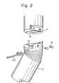
- Figure 2 is a disassembled view of another articulation unit according to the present invention.
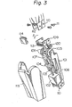
- Figure 3 is a disassembled view of still another articulation unit according to the present invention.
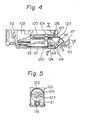
- Figure 4 is a side view of yet another articulation unit according to the present invention.
- Figure 5 is a sectional view of the articulation unit of Fig. 4 along line V-V of Fig. 4.
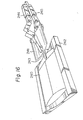
- Figure 6 is a perspective view of a robot comprising a plurality of articulation units, each unit being the type of Fig. 4.
- Figure 7 is a perspective view of still another articulation unit according to the present invention.
- Figure 8 is a perspective view of yet another articulation unit according to the present invention.
- Figure 9 is a disassembled view of the articulation unit of Fig. 8.
- Figure 10 is a perspective view of still another articulation unit according to the present invention.
- Figure 11 is a disassembled view of the articulation unit of Fig. 10.
- Figure 12 is a perspective view of a robot arm in accordance with the present invention.
- Figure 13-is a perspective view of another robot arm in accordance with the present invention.
- Figure 14 is a constructional view of the hand of the robot of Fig. 13, with hand being closed.
- Figure 15 is a constructional view of the hand of Fig. 14, with the hand being open.
- Figure 16 is a perspective view of still another robot arm in accordance with the present invention.
- Figure 17 is a perspective view of yet another
- robot arm in accordance with the present invention. Figure 18 is a perspective view of still another robot arm in accordance with the present invention.
- An example of the articulation unit in accordance with the present invention is illustrated in Fig. 1. The
articulation unit 1 comprises abody 2 and aconnection member 3 which is rotatable about an axis 4 disposed at the upper end of thebody 2. Theconnection member 3 comprisesprojections 6 at both sides thereof and a folded tongue 8 at the rear end thereof. Screwholes 7 are formed in the folded tongue 8. A connector 9 for electrically interconnecting articulation units is secured to theupper connection surface 5 of theconnection member 3. Aguide groove 10 for receiving theprojection 6 of theconnection member 3 is formed at the lower end of each side of thebody 2. Also, a connector 11 to be connected to the connector 9 is disposed at the lower end of thebody 2. The connectors 9 and 11 are interconnected by ashort plug 12. The insertion direction of theshort plug 12 is parallel with theconnection surface 5, as is shown by the arrow C. Theconnection member 3 is connected to amotor 15 via alinkage 13 and ascrew bar 14 which is screwed into thelinkage 13. Thescrew bar 14 rotates when themotor 15 is driven, with the result that thelinkage 13 moves along thescrew bar 14 and thereby theconnection member 3 is rotated about the axis 4, as is illustrated by the arrows A, so as to articulate the assembled articulation units. Theprojection 6 of theconnection member 3 is pushingly inserted into theguide groove 10 against the resiliency of aguide piece 10a which defines the lower part of theguide groove 10. Therefore, theprojection 6 is securely held. within theguide groove 10 after it is inserted thereinto. Then the two articulation units are firmly interconnected withscrews 16. The screwing direction of thescrews 16 is parallel with theconnection surface 5, as is shown by thearrow B. Cables 17, which are connected to the connectors 9 and 11, and themotor 15 are disposed within thebody 2. - Another example of the
articulation unit 1 in accordance with the present invention is illustrated in Fig. 2. Thisarticulation unit 1 comprises amagnet 18 at the upper end thereof and aferromagnetic material 19, such as iron, at the lower end thereof. Thearticulation units 1 are first connected by the magnetic force of themagnet 18. Then thearticulation units 1 are firmly interconnected withscrews 16.Reference numeral 20 designates a plug for actuating a coil (not shown) which weakens the force of themagnet 18 when thearticulation units 1 are disassembled. Other structures and functions of the articulation units are substantially the same as those of the example of Fig. 1. - Figure 3 is a disassembled view of another articulation unit in accordance with the present invention. A
motor 102 is installed in abody 101, and ascrew bar 103 is connected to the output of themotor 102. Anut member 104 is screwed onto thescrew bar 103 so that thenut member 104 moves along thescrew bar 103 in accordance with the rotation of thescrew bar 103. Twoendless belts 107, each of which engagespulleys nut member 104. Thepulley 105 is connected to aconnection member 109 viabevel gears 108.Cables 120 of power lines and signal lines are disposed in thebody 101. Thecables 120 are of a sufficient length to enable smooth movement of theconnection member 109. Aconnector 113, to which thecables 120 are connected, is secured to the upper surface of theconnection member 109. Theconnector 113 is connected, via ashort plug 114, to aconnector 112 disposed at the lower end of a second articulation unit to be assembled with a first (the above-mentioned) articulation unit. The articulation units are interconnected in such a manner that an attachingpiece 110 formed at the lower end of thebody 101 can be secured with screws 111 to theconnection member 109 formed at the upper end of the first articulation unit to be interconnected with the second articulation unit. Thebody 101 is covered by acover 115. When themotor 102 is driven, thepulleys nut member 104 and theendless belts 107. Thereby, theconnection member 109 articulates via the bevel gears 108. - The rotation of the
pulleys connection member 109 so that theconnection member 109 swings, as is shown by the arrows A, thereby obviating the necessity of the bevel gears 108. - Another example of the articulation unit in accordance with the present invention is illustrated in Figs. 4 and 5. A
motor 102 is installed in abody 101, and ascrew bar 103 is connected to the output of themotor 102. Anut member 104 is screwed onto the screw bar-103, and abelt 107 is secured to thenut member 104. Thebelt 107 engages asector member 116 which is rotatable about anaxis 118. Similar to the example of Fig. 3, themotor 102 actuates thesector member 116 via thescrew bar 103, thenut member 104, and thebelt 107 so that aconnection member 117 secured to thesector member 116 articulates as is shown by the arrows B. Aspring 119 is disposed within thebody 101 so as to restore thesector member 116 to its original position. The backlash of thescrew bar 103 and thesector member 116 is absorbed by thespring 119. Thespring 119 is covered by asleeve 121, which prevents thecables 120 from becoming entangled with thespring 119. Thesleeve 121 also guides thenut member 104 and prevents the rotation thereof. - A plurality of the above-mentioned articulation units are assembled so as to constitute a multi--articulated robot arm having a
hand 122 at the end thereof, as is illustrated in Fig. 6. A strain gauge 124 (Fig. 4) may be attached to thebelt 107 so as to detect the force applied to the articulation. Also, magnetic tape 123 (Fig. 4) may be attached to thebelt 107 so as to form a position detection means in cooperation with a magnetic sensor 125 (Fig. 4) secured to thebody 101. - Another example of the articulation unit in accordance with the present invention is illustrated in Fig. 7. This articulation unit comprises a bevel gear-transmission means comprising
bevel gears bevel gear 203 with which thebevel gears bevel gear 203 is connected, is rotatable about the axis of thebevel gears bevel gear 203, as is shown by the arrow E, with respect to thebody 205 of the articulation unit. The bevel gears 201 and 202 are independently driven bymotors screw bar 208 is connected to themotor 206. Anut member 209 is screwed onto thescrew bar 208 so that thenut member 209 moves along thescrew bar 208 in accordance with the rotation of thescrew bar 208. One end of abelt 210 is secured to thenut member 209 and the other end is connected to aspring 211, which is secured to thebody 205. Thebevel gear 201 rotates, via thebelt 210, due to the movement of thenut member 209. Thebevel gear 202 is rotated by themotor 207 in a manner similar to the rotation of thebevel gear 201. - An extensible articulation unit is illustrated in Figs. 8 and 9. The articulation unit comprises a
body 212, amotor 213 installed within thebody 212, ascrew bar 214 connected to themotor 213, and anut member 215 screwed onto thescrew bar 214 so as to move along thescrew bar 214 in accordance with the rotation of thescrew bar 214. The articulation unit expands and contracts, in accordance with the movement of theconnection member 216 secured to thenut member 215, along the longitudinal axis of thebody 212, the movement of theconnection member 216 being due to the rotation of themotor 213. - A rotatable articulation unit is illustrated in Figs. 10 and 11. The articulation unit comprises a
body 217, amotor 218 installed within thebody 217, ascrew bar 219 connected to themotor 218, and anut member 220 movable along thescrew bar 219 in accordance with the rotation of thescrew bar 219.Screw threads 221 of a large lead are formed on thenut member 220. Acylinder 223 comprisinginner threads 222 which engage with theouter threads 221 of thenut member 220 is mounted on thenut member 220. When themotor 218 is rotated, thenut member 220 moves along thescrew bar 219 so that thecylinder 223 rotates about the longitudinal axis thereof along with theconnection member 224 attached thereto. A large torque can be obtained by transmitting the rotational'force from the motor to the cylinder via the nut member instead of directly transmitting the rotational force from the motor to the cylinder. - A robot arm for performing a desired movement can be constructed by appropriately assembling various types of the above-mentioned articulation units.
- As example of the articulated robot arm in accordance with the present invention is illustrated in Fig. 12. The robot arm of Fig. 12 comprises
articulation units grass 225. The rotatable and foldable articulation unit of Fig. 7 or the rotatable articulation unit of Fig. 11 may be used as thearticulation unit 227 of this robot. The foldable articulation unit of Fig. 1, 2, or 3 may be used as thearticulation unit 226. - Another example of the articulated robot arm in accordance with the present invention is illustrated in Fig. 13. The robot arm of Fig. 13 performs the operation of manipulating on
injector 228. Theinjector 228 is grasped by ahand 229. An example of the construction of such ahand 229 is illustrated in Figs. 14 and 15. Ascrew bar 231 is connected to the output of amotor 230, and anut member 232 is arranged on thescrew bar 231 so that it moves along thescrew bar 231 when thescrew bar 231 rotates. One end of each of two superposedbelts 233 is secured to thenut member 232 and the other end is secured torollers rollers Springs rollers fingers 236 and 23.7, respectively. When themotor 230 is driven so that thenut member 232 moves forward (rightward), thefingers springs motor 230 is reversely rotated so that thenut member 232 moves backward (leftward), thefingers - Another example of the articulated robot arm in accordance with the present invention is illustrated in Fig. 16. The robot arm of Fig. 16 performs the operation of inserting a piece of paper into an envelope. An
envelope 240 is placed on asupport 242, and ahandpiece 243 of the robot pushes down the flap of the envelope and opens the envelope. Then a piece ofpaper 241 is inserted into the envelope by theextensible articulation units - Another example of the articulated robot arm in accordance with the present invention is illustrated in Fig. 17. The robot arm of Fig. 17 performs the operation of picking fruit. A piece of
fruit 253 is detected by adetector 246, theleaves 254 are forced upward by thehandpieces 247, and thestem 248 is cut withscissors 248. - Another example of the articulated robot arm in accordance with the present invention is illustrated in Fig. 18. The robot arm of Fig. 18 performs the operation of turning the pages of a book. A
wedge 250 is inserted into abook 249. The uppermost page is separated from the other pages by arubber roller 251. Then ahandpiece 252 is inserted into the gap beneath the uppermost page and turns the uppermost page over. - As was mentioned above, the multi-articulated robot in accordance with the present invention comprises a plurality of articulation units, each of which comprises an independent drive means and performs a desired movement. Therefore, by appropriately selecting and assembling the articulation units, a robot for performing a desired operation can be easily obtained. Also, the number of articulations can be easily increased or decreased, and the operation of the robot can be easily changed.
- As was previously mentioned, with reference to Figs. 1 and 2, the insertion direction of screws which interconnect the articulation units is parallel with the connection surface between the articulation units, i.e., substantially perpendicular to the longitudinal axis of each articulation unit, and the insertion direction of the projection of the connection member into the guide groove is also parallel with the connection surface. Further, the insertion direction of the short plug for electrically interconnecting the articulation units is also parallel with the connection surface between the articulation units. Therefore, there is no force component in the longitudinal direction of each articulation unit, thereby making it possible to prevent damaging of the inside structure of the articulation unit due to the force for combining the articulation units.
- Also, as was previously mentioned, with reference to Figs. 3, 4, and 5, the screw movement in connection with the motor is converted to an articulation movement via the belt and the rotatable member which engages the belt. The rotational angle of the motor precisely corresponds to the rotational angle of the articulation unit. Therefore, accurate control of the articulation movement can be easily achieved. Also, detectors for detecting the force applied to the articulaton unit and the angular position of the articulation unit can be easily attached thereto so that the force, position, and acceleration of the articulation unit can be easily detected, thereby achieving accurate control of the robot arm.
Claims (5)
Applications Claiming Priority (4)
| Application Number | Priority Date | Filing Date | Title |
|---|---|---|---|
| JP16598282A JPS5959385A (en) | 1982-09-25 | 1982-09-25 | Joint unit |
| JP165982/82 | 1982-09-25 | ||
| JP16672282A JPS5959386A (en) | 1982-09-27 | 1982-09-27 | Joint unit |
| JP166722/82 | 1982-09-27 |
Publications (3)
| Publication Number | Publication Date |
|---|---|
| EP0108657A2 true EP0108657A2 (en) | 1984-05-16 |
| EP0108657A3 EP0108657A3 (en) | 1984-06-13 |
| EP0108657B1 EP0108657B1 (en) | 1987-08-12 |
Family
ID=26490525
Family Applications (1)
| Application Number | Title | Priority Date | Filing Date |
|---|---|---|---|
| EP83401845A Expired EP0108657B1 (en) | 1982-09-25 | 1983-09-22 | A multi-articulated robot |
Country Status (5)
| Country | Link |
|---|---|
| US (1) | US4697472A (en) |
| EP (1) | EP0108657B1 (en) |
| CA (1) | CA1237740A (en) |
| DE (1) | DE3372942D1 (en) |
| NO (1) | NO159253C (en) |
Cited By (13)
| Publication number | Priority date | Publication date | Assignee | Title |
|---|---|---|---|---|
| GB2161136A (en) * | 1984-05-09 | 1986-01-08 | Silver Seiko | A method of and apparatus for mounting an electronic part on a circuit board |
| EP0187871A1 (en) * | 1984-07-23 | 1986-07-23 | Fanuc Ltd. | Industrial robot having variable arm structure |
| WO1987004653A1 (en) * | 1986-01-31 | 1987-08-13 | Robert Bosch Gmbh | Robot arm with tool mounting flange |
| WO1991000167A1 (en) * | 1989-06-30 | 1991-01-10 | National Research Development Corporation | Gripping and manipulating device and handling method |
| EP0441397A1 (en) * | 1990-02-09 | 1991-08-14 | Hitachi, Ltd. | Assembling a modular robot arm by means of a second robot arm |
| EP0433096A3 (en) * | 1989-12-14 | 1992-01-29 | Honda Giken Kogyo Kabushiki Kaisha | Articulated structure for legged walking robot |
| US5115690A (en) * | 1989-01-30 | 1992-05-26 | Fanuc Ltd. | Multi-articulated industrial robot with an offset robot arm |
| WO1998043782A1 (en) * | 1997-04-01 | 1998-10-08 | Charles Khairallah | Modular articulated robot structure |
| US6686717B2 (en) | 1997-04-01 | 2004-02-03 | Charles Khairallah | Modular articulated structure |
| WO2010092344A1 (en) * | 2009-02-16 | 2010-08-19 | Corcost Limited | Linkage |
| WO2016100939A1 (en) * | 2014-12-19 | 2016-06-23 | Kurion, Inc. | Systems and methods for chain joint cable routing |
| EP3505308A1 (en) * | 2017-12-28 | 2019-07-03 | Aeolus Robotics Corporation Limited | Robotic arm |
| US11969888B2 (en) | 2018-08-01 | 2024-04-30 | Veolia Nuclear Solutions, Inc. | Systems and methods for chain joint cable routing |
Families Citing this family (78)
| Publication number | Priority date | Publication date | Assignee | Title |
|---|---|---|---|---|
| JPS6263078A (en) * | 1985-09-11 | 1987-03-19 | フアナツク株式会社 | Module system in industrial robot |
| DE4003201C2 (en) * | 1990-02-03 | 1995-04-27 | Dango & Dienenthal Maschbau | Quick coupling device for forging and transport manipulators |
| US5129279A (en) * | 1991-02-28 | 1992-07-14 | Rennex Brian G | Flexible robotic limb |
| US5142212A (en) * | 1991-09-19 | 1992-08-25 | General Dynamics Corporation | Break-way end-of-arm robotic tooling assembly |
| SE513348C2 (en) * | 1993-07-02 | 2000-08-28 | Abb Ab | Industrial robot |
| DE4431842C2 (en) * | 1994-09-07 | 1998-10-01 | Gmd Gmbh | Electronically controllable device |
| JP3869465B2 (en) * | 1995-02-23 | 2007-01-17 | テラダイン・インコーポレーテッド | Manipulator for test head of automatic test equipment |
| DE19517852A1 (en) * | 1995-05-16 | 1995-12-14 | Uwe Kochanneck | Multi-unit robotic system with addn. of standard parts |
| US5656904A (en) * | 1995-09-28 | 1997-08-12 | Lander; Ralph | Movement monitoring and control apparatus for body members |
| DE19922728C2 (en) * | 1999-05-18 | 2003-08-21 | Udo Gnasa | boom system |
| SE522933C2 (en) * | 2001-08-02 | 2004-03-16 | Abb Ab | Industrial robot equipped with a detachable cabling |
| US20040162637A1 (en) | 2002-07-25 | 2004-08-19 | Yulun Wang | Medical tele-robotic system with a master remote station with an arbitrator |
| US6925357B2 (en) | 2002-07-25 | 2005-08-02 | Intouch Health, Inc. | Medical tele-robotic system |
| FR2852373B1 (en) * | 2003-03-14 | 2005-04-15 | Commissariat Energie Atomique | SCREW TRANSMISSION, NUT AND CABLE |
| FR2852265B1 (en) * | 2003-03-14 | 2006-02-24 | Commissariat Energie Atomique | INTERMEDIATE SEGMENT OF ARTICULATED ARMS CONTAINING SCREW AND NUT TRANSMISSION |
| US7813836B2 (en) | 2003-12-09 | 2010-10-12 | Intouch Technologies, Inc. | Protocol for a remotely controlled videoconferencing robot |
| US20050204438A1 (en) * | 2004-02-26 | 2005-09-15 | Yulun Wang | Graphical interface for a remote presence system |
| US8077963B2 (en) | 2004-07-13 | 2011-12-13 | Yulun Wang | Mobile robot with a head-based movement mapping scheme |
| JP4457794B2 (en) * | 2004-07-22 | 2010-04-28 | トヨタ自動車株式会社 | robot |
| US7444205B2 (en) * | 2004-10-29 | 2008-10-28 | Neil Desmond | Modular self structuring and computing system |
| US9198728B2 (en) | 2005-09-30 | 2015-12-01 | Intouch Technologies, Inc. | Multi-camera mobile teleconferencing platform |
| US8849679B2 (en) | 2006-06-15 | 2014-09-30 | Intouch Technologies, Inc. | Remote controlled robot system that provides medical images |
| US20070291128A1 (en) * | 2006-06-15 | 2007-12-20 | Yulun Wang | Mobile teleconferencing system that projects an image provided by a mobile robot |
| US7628093B2 (en) * | 2007-03-07 | 2009-12-08 | Disney Enterprises, Inc. | Three-axis robotic joint with human-based form factors |
| JP2008229762A (en) * | 2007-03-19 | 2008-10-02 | Fanuc Ltd | Robot having wire body storing type arm |
| US8265793B2 (en) | 2007-03-20 | 2012-09-11 | Irobot Corporation | Mobile robot for telecommunication |
| US9160783B2 (en) | 2007-05-09 | 2015-10-13 | Intouch Technologies, Inc. | Robot system that operates through a network firewall |
| US10875182B2 (en) | 2008-03-20 | 2020-12-29 | Teladoc Health, Inc. | Remote presence system mounted to operating room hardware |
| US8179418B2 (en) | 2008-04-14 | 2012-05-15 | Intouch Technologies, Inc. | Robotic based health care system |
| US8170241B2 (en) | 2008-04-17 | 2012-05-01 | Intouch Technologies, Inc. | Mobile tele-presence system with a microphone system |
| KR20090128878A (en) * | 2008-06-11 | 2009-12-16 | 삼성전자주식회사 | Robot joint driving apparatus and robot having the same |
| US9193065B2 (en) | 2008-07-10 | 2015-11-24 | Intouch Technologies, Inc. | Docking system for a tele-presence robot |
| US9842192B2 (en) | 2008-07-11 | 2017-12-12 | Intouch Technologies, Inc. | Tele-presence robot system with multi-cast features |
| US8340819B2 (en) | 2008-09-18 | 2012-12-25 | Intouch Technologies, Inc. | Mobile videoconferencing robot system with network adaptive driving |
| US8996165B2 (en) | 2008-10-21 | 2015-03-31 | Intouch Technologies, Inc. | Telepresence robot with a camera boom |
| US8041456B1 (en) | 2008-10-22 | 2011-10-18 | Anybots, Inc. | Self-balancing robot including an ultracapacitor power source |
| US8160747B1 (en) | 2008-10-24 | 2012-04-17 | Anybots, Inc. | Remotely controlled self-balancing robot including kinematic image stabilization |
| US9138891B2 (en) | 2008-11-25 | 2015-09-22 | Intouch Technologies, Inc. | Server connectivity control for tele-presence robot |
| US8442661B1 (en) | 2008-11-25 | 2013-05-14 | Anybots 2.0, Inc. | Remotely controlled self-balancing robot including a stabilized laser pointer |
| US8463435B2 (en) | 2008-11-25 | 2013-06-11 | Intouch Technologies, Inc. | Server connectivity control for tele-presence robot |
| KR20100077504A (en) * | 2008-12-29 | 2010-07-08 | 삼성전자주식회사 | Robot joint driving apparatus and robot having the same |
| US20100180711A1 (en) | 2009-01-19 | 2010-07-22 | Comau, Inc. | Robotic end effector system and method |
| US8849680B2 (en) | 2009-01-29 | 2014-09-30 | Intouch Technologies, Inc. | Documentation through a remote presence robot |
| US8897920B2 (en) | 2009-04-17 | 2014-11-25 | Intouch Technologies, Inc. | Tele-presence robot system with software modularity, projector and laser pointer |
| US11399153B2 (en) | 2009-08-26 | 2022-07-26 | Teladoc Health, Inc. | Portable telepresence apparatus |
| US8384755B2 (en) | 2009-08-26 | 2013-02-26 | Intouch Technologies, Inc. | Portable remote presence robot |
| KR20110026935A (en) * | 2009-09-09 | 2011-03-16 | 삼성전자주식회사 | Structure of robot joint and robot having the same |
| CN102072293B (en) * | 2009-11-23 | 2013-11-20 | 鸿富锦精密工业(深圳)有限公司 | Speed reducing mechanism and transmission device adopted by same |
| US20110137423A1 (en) * | 2009-12-04 | 2011-06-09 | Hsiang Ouyang | Mechanical joint imitating creatures' joints |
| CN102107434B (en) * | 2009-12-29 | 2013-10-09 | 鸿富锦精密工业(深圳)有限公司 | Arm component for robot |
| KR101706094B1 (en) * | 2010-01-14 | 2017-02-14 | 삼성전자주식회사 | Robot joint driving apparatus and robot having the same, cable linking method of robot joint driving apparatus |
| US11154981B2 (en) | 2010-02-04 | 2021-10-26 | Teladoc Health, Inc. | Robot user interface for telepresence robot system |
| KR101691941B1 (en) * | 2010-02-10 | 2017-01-17 | 삼성전자주식회사 | Robot joint driving apparatus and joint torque measuring method of the same |
| US8670017B2 (en) | 2010-03-04 | 2014-03-11 | Intouch Technologies, Inc. | Remote presence system including a cart that supports a robot face and an overhead camera |
| CN102198658A (en) * | 2010-03-25 | 2011-09-28 | 鸿富锦精密工业(深圳)有限公司 | Robot arm assembly |
| US8788096B1 (en) | 2010-05-17 | 2014-07-22 | Anybots 2.0, Inc. | Self-balancing robot having a shaft-mounted head |
| US9014848B2 (en) | 2010-05-20 | 2015-04-21 | Irobot Corporation | Mobile robot system |
| US8918213B2 (en) | 2010-05-20 | 2014-12-23 | Irobot Corporation | Mobile human interface robot |
| US8935005B2 (en) | 2010-05-20 | 2015-01-13 | Irobot Corporation | Operating a mobile robot |
| US10343283B2 (en) | 2010-05-24 | 2019-07-09 | Intouch Technologies, Inc. | Telepresence robot system that can be accessed by a cellular phone |
| US10808882B2 (en) | 2010-05-26 | 2020-10-20 | Intouch Technologies, Inc. | Tele-robotic system with a robot face placed on a chair |
| CN102398270B (en) * | 2010-09-16 | 2014-03-26 | 鸿富锦精密工业(深圳)有限公司 | Robot arm part |
| US9264664B2 (en) | 2010-12-03 | 2016-02-16 | Intouch Technologies, Inc. | Systems and methods for dynamic bandwidth allocation |
| US8930019B2 (en) | 2010-12-30 | 2015-01-06 | Irobot Corporation | Mobile human interface robot |
| US9323250B2 (en) | 2011-01-28 | 2016-04-26 | Intouch Technologies, Inc. | Time-dependent navigation of telepresence robots |
| KR102018763B1 (en) | 2011-01-28 | 2019-09-05 | 인터치 테크놀로지스 인코퍼레이티드 | Interfacing with a mobile telepresence robot |
| US10769739B2 (en) | 2011-04-25 | 2020-09-08 | Intouch Technologies, Inc. | Systems and methods for management of information among medical providers and facilities |
| US9098611B2 (en) | 2012-11-26 | 2015-08-04 | Intouch Technologies, Inc. | Enhanced video interaction for a user interface of a telepresence network |
| US20140139616A1 (en) | 2012-01-27 | 2014-05-22 | Intouch Technologies, Inc. | Enhanced Diagnostics for a Telepresence Robot |
| US8836751B2 (en) | 2011-11-08 | 2014-09-16 | Intouch Technologies, Inc. | Tele-presence system with a user interface that displays different communication links |
| US8902278B2 (en) | 2012-04-11 | 2014-12-02 | Intouch Technologies, Inc. | Systems and methods for visualizing and managing telepresence devices in healthcare networks |
| US9251313B2 (en) | 2012-04-11 | 2016-02-02 | Intouch Technologies, Inc. | Systems and methods for visualizing and managing telepresence devices in healthcare networks |
| US9361021B2 (en) | 2012-05-22 | 2016-06-07 | Irobot Corporation | Graphical user interfaces including touchpad driving interfaces for telemedicine devices |
| WO2013176758A1 (en) | 2012-05-22 | 2013-11-28 | Intouch Technologies, Inc. | Clinical workflows utilizing autonomous and semi-autonomous telemedicine devices |
| US11862302B2 (en) | 2017-04-24 | 2024-01-02 | Teladoc Health, Inc. | Automated transcription and documentation of tele-health encounters |
| US10483007B2 (en) | 2017-07-25 | 2019-11-19 | Intouch Technologies, Inc. | Modular telehealth cart with thermal imaging and touch screen user interface |
| US11636944B2 (en) | 2017-08-25 | 2023-04-25 | Teladoc Health, Inc. | Connectivity infrastructure for a telehealth platform |
| US10617299B2 (en) | 2018-04-27 | 2020-04-14 | Intouch Technologies, Inc. | Telehealth cart that supports a removable tablet with seamless audio/video switching |
Citations (4)
| Publication number | Priority date | Publication date | Assignee | Title |
|---|---|---|---|---|
| GB1455782A (en) * | 1973-01-12 | 1976-11-17 | Fischer Brodbeck Gmbh | Manipulator |
| DE2345856B2 (en) * | 1973-09-12 | 1977-01-27 | Arnswald, Werner, Dipl.-Ing., 5204 Lohrnar; Wagner, Gerald D., Dr.-Ing., 8013 Haar | MANIPULATOR |
| EP0000877A1 (en) * | 1977-08-31 | 1979-03-07 | Grisebach, Hans-Theodor | Manipulator for positionning workpieces or other loads |
| GB2053148A (en) * | 1979-07-18 | 1981-02-04 | Bretagne Atel Chantiers | Remote manipulator arm |
Family Cites Families (14)
| Publication number | Priority date | Publication date | Assignee | Title |
|---|---|---|---|---|
| GB779411A (en) * | 1954-10-05 | 1957-07-17 | Thomas Harley Haddow | Improvements in joints or coupling devices for structural members |
| US3614898A (en) * | 1969-08-07 | 1971-10-26 | Nasa | Positioning mechanism |
| AT338410B (en) * | 1975-09-18 | 1977-08-25 | Viennatone Gmbh | TRANSMISSION FOR AN ORTHESIS, PROSTHESIS OR DGL. |
| FR2324407A1 (en) * | 1975-09-22 | 1977-04-15 | Sofermo | MODULAR ROBOT OF ADAPTABLE CONFIGURATION |
| DE2754609A1 (en) * | 1977-12-08 | 1979-06-13 | Karlsruhe Augsburg Iweka | Industrial robot manipulator pivot spindle drive unit - comprises three independent modules positively secured together |
| IT1109055B (en) * | 1978-02-17 | 1985-12-16 | Comau Ind S P A | MANIPULATOR APPARATUS |
| SU766855A1 (en) * | 1978-08-17 | 1980-09-30 | Особое Конструкторское Бюро Технической Кибернетики Ленинградского Политехнического Института Им.М.И.Калинина | Working member of industrial robot |
| DE7828226U1 (en) * | 1978-09-22 | 1987-01-02 | H.A. Schlatter Ag, Schlieren, Zuerich, Ch | |
| DE2851063A1 (en) * | 1978-11-25 | 1980-06-04 | Cloos Gmbh Carl | DEVICE FOR AUTOMATICALLY GUIDING A WELDING GUN LONG A PRE-PROGRAMMED WELDING SEAM |
| US4225191A (en) * | 1979-03-29 | 1980-09-30 | Knoski Jerry L | Quick change wheel assembly |
| SE422291B (en) * | 1980-07-03 | 1982-03-01 | Esab Ab | SENSOR |
| AT384093B (en) * | 1981-08-17 | 1987-09-25 | Igm Ind Geraete Maschf Gmbh | REDUCTION GEARBOX |
| US4488241A (en) * | 1981-12-08 | 1984-12-11 | Zymark Corporation | Robot system with interchangeable hands |
| US4441376A (en) * | 1982-04-30 | 1984-04-10 | Martin Marietta Corporation | Motor driven hinge assembly |
-
1983
- 1983-09-22 DE DE8383401845T patent/DE3372942D1/en not_active Expired
- 1983-09-22 EP EP83401845A patent/EP0108657B1/en not_active Expired
- 1983-09-23 NO NO833424A patent/NO159253C/en unknown
- 1983-09-23 CA CA000437466A patent/CA1237740A/en not_active Expired
- 1983-09-26 US US06/535,837 patent/US4697472A/en not_active Expired - Fee Related
Patent Citations (4)
| Publication number | Priority date | Publication date | Assignee | Title |
|---|---|---|---|---|
| GB1455782A (en) * | 1973-01-12 | 1976-11-17 | Fischer Brodbeck Gmbh | Manipulator |
| DE2345856B2 (en) * | 1973-09-12 | 1977-01-27 | Arnswald, Werner, Dipl.-Ing., 5204 Lohrnar; Wagner, Gerald D., Dr.-Ing., 8013 Haar | MANIPULATOR |
| EP0000877A1 (en) * | 1977-08-31 | 1979-03-07 | Grisebach, Hans-Theodor | Manipulator for positionning workpieces or other loads |
| GB2053148A (en) * | 1979-07-18 | 1981-02-04 | Bretagne Atel Chantiers | Remote manipulator arm |
Cited By (22)
| Publication number | Priority date | Publication date | Assignee | Title |
|---|---|---|---|---|
| GB2161136A (en) * | 1984-05-09 | 1986-01-08 | Silver Seiko | A method of and apparatus for mounting an electronic part on a circuit board |
| EP0187871A1 (en) * | 1984-07-23 | 1986-07-23 | Fanuc Ltd. | Industrial robot having variable arm structure |
| EP0187871B1 (en) * | 1984-07-23 | 1991-06-26 | Fanuc Ltd. | Industrial robot having variable arm structure |
| WO1987004653A1 (en) * | 1986-01-31 | 1987-08-13 | Robert Bosch Gmbh | Robot arm with tool mounting flange |
| US5115690A (en) * | 1989-01-30 | 1992-05-26 | Fanuc Ltd. | Multi-articulated industrial robot with an offset robot arm |
| WO1991000167A1 (en) * | 1989-06-30 | 1991-01-10 | National Research Development Corporation | Gripping and manipulating device and handling method |
| EP0791439A3 (en) * | 1989-12-14 | 1997-09-10 | Honda Giken Kogyo Kabushiki Kaisha | Articulated structure for legged walking robot |
| EP0433096A3 (en) * | 1989-12-14 | 1992-01-29 | Honda Giken Kogyo Kabushiki Kaisha | Articulated structure for legged walking robot |
| US5159988A (en) * | 1989-12-14 | 1992-11-03 | Honda Giken Kogyo Kabushiki Kaisha | Articulated structure for legged walking robot |
| EP0791439A2 (en) * | 1989-12-14 | 1997-08-27 | Honda Giken Kogyo Kabushiki Kaisha | Articulated structure for legged walking robot |
| EP0441397A1 (en) * | 1990-02-09 | 1991-08-14 | Hitachi, Ltd. | Assembling a modular robot arm by means of a second robot arm |
| WO1998043782A1 (en) * | 1997-04-01 | 1998-10-08 | Charles Khairallah | Modular articulated robot structure |
| US6323615B1 (en) | 1997-04-01 | 2001-11-27 | Charles Khairallah | Modular articulated robot structure |
| US6686717B2 (en) | 1997-04-01 | 2004-02-03 | Charles Khairallah | Modular articulated structure |
| WO2010092344A1 (en) * | 2009-02-16 | 2010-08-19 | Corcost Limited | Linkage |
| WO2016100939A1 (en) * | 2014-12-19 | 2016-06-23 | Kurion, Inc. | Systems and methods for chain joint cable routing |
| US10065308B2 (en) | 2014-12-19 | 2018-09-04 | Kurion, Inc. | Systems and methods for chain joint cable routing |
| EP4306809A2 (en) | 2014-12-19 | 2024-01-17 | Veolia Nuclear Solutions, Inc. | Systems and methods for chain joint cable routing |
| EP4306809A3 (en) * | 2014-12-19 | 2024-04-10 | Veolia Nuclear Solutions, Inc. | Systems and methods for chain joint cable routing |
| EP3505308A1 (en) * | 2017-12-28 | 2019-07-03 | Aeolus Robotics Corporation Limited | Robotic arm |
| US10673303B2 (en) | 2017-12-28 | 2020-06-02 | Aeolus Robotics Corporation Limited | Robotic arm |
| US11969888B2 (en) | 2018-08-01 | 2024-04-30 | Veolia Nuclear Solutions, Inc. | Systems and methods for chain joint cable routing |
Also Published As
| Publication number | Publication date |
|---|---|
| NO159253C (en) | 1988-12-14 |
| EP0108657A3 (en) | 1984-06-13 |
| NO833424L (en) | 1984-03-26 |
| NO159253B (en) | 1988-09-05 |
| DE3372942D1 (en) | 1987-09-17 |
| US4697472A (en) | 1987-10-06 |
| EP0108657B1 (en) | 1987-08-12 |
| CA1237740A (en) | 1988-06-07 |
Similar Documents
| Publication | Publication Date | Title |
|---|---|---|
| EP0108657B1 (en) | A multi-articulated robot | |
| EP1354670B1 (en) | Multi-finger hand device | |
| US4946380A (en) | Artificial dexterous hand | |
| US6244644B1 (en) | Compact dexterous robotic hand | |
| US6918622B2 (en) | Robot hand and robot hand finger | |
| KR850000907A (en) | Corn harvester | |
| US20050040663A1 (en) | Palm mechanism for robot hand | |
| CA2170793A1 (en) | Neutral Start Mechanism for a Hydrostatic Transmission | |
| CA2198923A1 (en) | Farm machinery with a linkage to a tractor and a pivoting gear housing | |
| DE10261218B4 (en) | Flap drive device for a portable device | |
| CA2189410A1 (en) | Current Collector for Transmitting Energy Between a Contact Wire and a Motor Coach | |
| AU615149B2 (en) | Header for a combine harvesting machine | |
| EP0608963A3 (en) | Device for taking out ensilage material | |
| US6299228B1 (en) | Gripper apparatus for robots | |
| CA2047311A1 (en) | Operating mechanism for a blind or shielding device | |
| EP1190880A1 (en) | Devise for detecting an angular position | |
| CA2041320A1 (en) | Coupling device for an electrical cable coupling and a mechanical middle buffer coupling | |
| US6247580B1 (en) | Actuator for a bi-directional conveyor belt | |
| CN115570580A (en) | Tendon rope under-actuated five-finger dexterous hand with variable finger rigidity | |
| JPH04189489A (en) | Manipulator hand for exchange | |
| CA1108668A (en) | Manipulator arm having co-ordinated extend/retract motion | |
| DE4236279A1 (en) | Brushless electric signal transmitter - has rotor in slightly larger housing and flexible electric connector, coupling rotor to housing inside | |
| JPS61125790A (en) | Preventive mechanism of cutting of cable for industrial robot | |
| JPH01274989A (en) | Grip hand | |
| JPH0911171A (en) | Combining device and manipulator |
Legal Events
| Date | Code | Title | Description |
|---|---|---|---|
| PUAI | Public reference made under article 153(3) epc to a published international application that has entered the european phase |
Free format text: ORIGINAL CODE: 0009012 |
|
| PUAL | Search report despatched |
Free format text: ORIGINAL CODE: 0009013 |
|
| AK | Designated contracting states |
Designated state(s): DE FR GB IT SE |
|
| AK | Designated contracting states |
Designated state(s): DE FR GB IT SE |
|
| 17P | Request for examination filed |
Effective date: 19841211 |
|
| 17Q | First examination report despatched |
Effective date: 19860221 |
|
| GRAA | (expected) grant |
Free format text: ORIGINAL CODE: 0009210 |
|
| AK | Designated contracting states |
Kind code of ref document: B1 Designated state(s): DE FR GB IT SE |
|
| REF | Corresponds to: |
Ref document number: 3372942 Country of ref document: DE Date of ref document: 19870917 |
|
| ITF | It: translation for a ep patent filed |
Owner name: STUDIO JAUMANN |
|
| ET | Fr: translation filed | ||
| PLBE | No opposition filed within time limit |
Free format text: ORIGINAL CODE: 0009261 |
|
| STAA | Information on the status of an ep patent application or granted ep patent |
Free format text: STATUS: NO OPPOSITION FILED WITHIN TIME LIMIT |
|
| 26N | No opposition filed | ||
| ITTA | It: last paid annual fee | ||
| PGFP | Annual fee paid to national office [announced via postgrant information from national office to epo] |
Ref country code: GB Payment date: 19920707 Year of fee payment: 10 |
|
| PGFP | Annual fee paid to national office [announced via postgrant information from national office to epo] |
Ref country code: SE Payment date: 19920813 Year of fee payment: 10 |
|
| PGFP | Annual fee paid to national office [announced via postgrant information from national office to epo] |
Ref country code: FR Payment date: 19920929 Year of fee payment: 10 |
|
| PGFP | Annual fee paid to national office [announced via postgrant information from national office to epo] |
Ref country code: DE Payment date: 19921125 Year of fee payment: 10 |
|
| PG25 | Lapsed in a contracting state [announced via postgrant information from national office to epo] |
Ref country code: GB Effective date: 19930922 |
|
| PG25 | Lapsed in a contracting state [announced via postgrant information from national office to epo] |
Ref country code: SE Effective date: 19930923 |
|
| GBPC | Gb: european patent ceased through non-payment of renewal fee |
Effective date: 19930922 |
|
| PG25 | Lapsed in a contracting state [announced via postgrant information from national office to epo] |
Ref country code: FR Free format text: LAPSE BECAUSE OF NON-PAYMENT OF DUE FEES Effective date: 19940531 |
|
| PG25 | Lapsed in a contracting state [announced via postgrant information from national office to epo] |
Ref country code: DE Effective date: 19940601 |
|
| REG | Reference to a national code |
Ref country code: FR Ref legal event code: ST |
|
| EUG | Se: european patent has lapsed |
Ref document number: 83401845.9 Effective date: 19940410 |