EP0108577A1 - Power transmission apparatus - Google Patents
Power transmission apparatus Download PDFInfo
- Publication number
- EP0108577A1 EP0108577A1 EP83306594A EP83306594A EP0108577A1 EP 0108577 A1 EP0108577 A1 EP 0108577A1 EP 83306594 A EP83306594 A EP 83306594A EP 83306594 A EP83306594 A EP 83306594A EP 0108577 A1 EP0108577 A1 EP 0108577A1
- Authority
- EP
- European Patent Office
- Prior art keywords
- rotation
- input
- output
- shaft
- input shaft
- Prior art date
- Legal status (The legal status is an assumption and is not a legal conclusion. Google has not performed a legal analysis and makes no representation as to the accuracy of the status listed.)
- Withdrawn
Links
Images


Classifications
-
- F—MECHANICAL ENGINEERING; LIGHTING; HEATING; WEAPONS; BLASTING
- F16—ENGINEERING ELEMENTS AND UNITS; GENERAL MEASURES FOR PRODUCING AND MAINTAINING EFFECTIVE FUNCTIONING OF MACHINES OR INSTALLATIONS; THERMAL INSULATION IN GENERAL
- F16H—GEARING
- F16H39/00—Rotary fluid gearing using pumps and motors of the volumetric type, i.e. passing a predetermined volume of fluid per revolution
- F16H39/04—Rotary fluid gearing using pumps and motors of the volumetric type, i.e. passing a predetermined volume of fluid per revolution with liquid motor and pump combined in one unit
- F16H39/06—Rotary fluid gearing using pumps and motors of the volumetric type, i.e. passing a predetermined volume of fluid per revolution with liquid motor and pump combined in one unit pump and motor being of the same type
- F16H39/08—Rotary fluid gearing using pumps and motors of the volumetric type, i.e. passing a predetermined volume of fluid per revolution with liquid motor and pump combined in one unit pump and motor being of the same type each with one main shaft and provided with pistons reciprocating in cylinders
- F16H39/10—Rotary fluid gearing using pumps and motors of the volumetric type, i.e. passing a predetermined volume of fluid per revolution with liquid motor and pump combined in one unit pump and motor being of the same type each with one main shaft and provided with pistons reciprocating in cylinders with cylinders arranged around, and parallel or approximately parallel to the main axis of the gearing
- F16H39/14—Rotary fluid gearing using pumps and motors of the volumetric type, i.e. passing a predetermined volume of fluid per revolution with liquid motor and pump combined in one unit pump and motor being of the same type each with one main shaft and provided with pistons reciprocating in cylinders with cylinders arranged around, and parallel or approximately parallel to the main axis of the gearing with cylinders carried in rotary cylinder blocks or cylinder-bearing members
-
- F—MECHANICAL ENGINEERING; LIGHTING; HEATING; WEAPONS; BLASTING
- F16—ENGINEERING ELEMENTS AND UNITS; GENERAL MEASURES FOR PRODUCING AND MAINTAINING EFFECTIVE FUNCTIONING OF MACHINES OR INSTALLATIONS; THERMAL INSULATION IN GENERAL
- F16D—COUPLINGS FOR TRANSMITTING ROTATION; CLUTCHES; BRAKES
- F16D31/00—Fluid couplings or clutches with pumping sets of the volumetric type, i.e. in the case of liquid passing a predetermined volume per revolution
- F16D31/02—Fluid couplings or clutches with pumping sets of the volumetric type, i.e. in the case of liquid passing a predetermined volume per revolution using pumps with pistons or plungers working in cylinders
-
- F—MECHANICAL ENGINEERING; LIGHTING; HEATING; WEAPONS; BLASTING
- F16—ENGINEERING ELEMENTS AND UNITS; GENERAL MEASURES FOR PRODUCING AND MAINTAINING EFFECTIVE FUNCTIONING OF MACHINES OR INSTALLATIONS; THERMAL INSULATION IN GENERAL
- F16D—COUPLINGS FOR TRANSMITTING ROTATION; CLUTCHES; BRAKES
- F16D31/00—Fluid couplings or clutches with pumping sets of the volumetric type, i.e. in the case of liquid passing a predetermined volume per revolution
- F16D31/08—Control of slip
Definitions
- the invention relates to a power transmission apparatus for driving an output shaft from an input shaft.
- the invention in one arrangement, relates to power transmission apparatus which will permit selective drive of the output shaft at a variable gear ratio with respect to the input shaft.
- the invention also relates to methods of operation of such power transmission apparatus.
- the method and apparatus may, in a preferred embodiment, allow the variation of drive of the output shaft from the input shaft in a ratio which is both positive and negative.
- a wide variety of clutch and transmission mechanisms are known in which hydraulic power is employed for the drive and/or control.
- clutch engagement is effected by means of high friction surfaces which lead to high wear forces requiring frequent replacement of the friction elements. Additionally, heat is generated during engagement and disengagement of the clutch which must be dissipated.
- hydraulic transmissions it is necessary to circulate a volume of hydraulic fluid at high speeds which leads to generation of heat and substantial energy losses.
- the hydraulic fluid has high inertia whgich opposes rapid variations in speed change.
- mechanical clutches it is necessary to apply high force to the engaging members to hold them in engaged relation when the clutch is operative.
- wobble plate or swash-type drive mechanisms for hydraulica and pneumatic pumps and motors.
- the present invention provides, according to a first aspect, apparatus for transmitting power from an input shaft having an axis of rotation to an output shaft, said apparatus comprising variable displacement pumping means secured to said output shaft and including a movable member for pumping a fluid, means connected to said input shaft for producing movement of said movable member in response to rotation of said input shaft, and means for controllably damping movement of said member to produce controlled rotation of said output shaft in correspondence therewith whereby the output shaft can be driven from the input shaft with a variable degree of rotation.
- the present invention provides, according to a further aspect, power transmitting apparatus comprising an input shaft having an axis of rotation, an input plate mounted on said input shaft for adjustable angular position relative to said axis of rotation, an output shaft, an output plate mounted for universal movement on said output shaft, means connecting said input and output plates together in coupled relation and permitting angular rotation relative to one another, means for adjusting the angular position of said input plate relative to said input shaft and thereby the angular position of the output plate therewith relative to said output shaft, and means secured to said output shaft and connected to said output plate for controllably holding the output plate in said angular position whereby the output plate becomes coupled in rotation with the input plate and said output shaft is driven in rotation.
- the present invention provides, according to a further aspect, a method of controllably transmitting torque between an input shaft and an output shaft, said method comprising producing movement of a member in a container containing an incompressible fluid in response to rotation of the input shaft, controllably damping external circulation of the fluid in said container to damp movement of said member in said container and rotating the output shaft in response to the degree of damping of the movement of said member in said container.
- the present invention provides, according to a further aspect, apparatus for transmitting power from an input shaft having an axis of rotation to an output shaft, said apparatus comprising variable displacement hydrostatic pumping means secured to said output shaft for producing fluid flow upon differential rotation of said input and output shafts, and power control means for controlling said fluid flow by selectively absorbing or dissipating the power of the fluid flow whereby the output shaft can be driven by the input shaft with a variable degree of rotation.
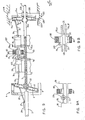
- FIG. 1 of the drawings therein is shown power transmitting apparatus in the form of a clutch mechanism 1 having a variable degree of engagement between an input shaft 2 and an output shaft 3.
- the variable degree of engagement is provided by a swash mechanism 4 and a variable damping mechanism 5 as will be explained in detail, subsequently.
- the input shaft 2 is driven in rotation from a source (not shown) around axis X-X.
- the input shaft 2 and the output shaft 3 are axially aligned.
- the swash plate mechanism 4 comprises an input plate 6 and a facing output plate 7 between which is a bearing mechansim illustrated as a ball-bearing 8 which permits relative angular rotation of input plates 6 and 7 with respect to the axis of rotation X-X of the input shaft 2.
- the input plate 6 is supported on a frame 9 which is fixed to the input shaft 2.
- the support of the input plate 6 is by pivot pins 10 which are fitted in slots 11 in the frame 9 to permit the input plate 6 to undergo pivotal movement about axis X-X.
- an actuator or control disk 20 is spline connected to the shaft 2 such that it is coupled in rotation therewith but is capable of relative axial movement therealong.
- a slide 21 which is supported on fixed structure for axial travel parallel to axis X-X straddles the disk 20 to displace the same axially in opposite directions along input shaft 2.
- the slide 21 is externally actuated for movement in the direction shown by the double arrows designated by numeral 22.
- the disk 20 is connected to the input plate 6 by a linkage mechanism 23 such that travel of disk 20 produces pivotal movment of input plate 6.
- the link mechanism 23 comprises a control rod 24 which is pivotably connected to disk 20.
- a pair of locking rods 25 and 26 are connected to the free end of rod 24.
- the rod 25 is pivotably connected to the input shaft 2 and the rod 26 carried a pin 27 at its lower end which is slidable in a guide slot 28 on the input shaft 2.
- a swash rod 29 is pivotally mounted at one end on pin 27 and at the other end, the rod 29 is pivotably connected to input plate 6 at a location offset from the centre of the plate. In the position illustrated in Figure 1, the input plate extends in a plane perpendicular to the axis of rotation X-X of input shaft 2.
- the output plate 7 of the swash mechanism is mounted on a spherical coupling 30 whose centre is concentric with the travel path of pivot pins 10.
- the output plate 7 is capable of undergoing universal movement on the spherical coupling 30.
- a plurality of connecting rods 31 are pivotably connected to the output plate 7 by ball joints 32.
- the connecting rods 31 are connected by ball joints 33 at their opposite ends to piston rods 34.
- the piston rods 34 carry pistons 35 which are supported for reciprocal slidable movement in cylinders 36 formed in housing 37 of the damping mechanism 5.
- the pistons 35 mounted in the cylinders 36 constitute a variable displacement pumping means for a hyudraulic fluid in the housing 37.
- the damping mechanism comprises a rotatable valve 38 in the housing 37. At each of its ends, the cylinder 36 is connected by ports 39 with a chamber 40 containing the valve 38.
- the valve has a constructin including a riased part 41 and a recessed part 42. In the position shown, the recessed part 42 permits free communication between the cylinder 36 and the chamber 40 via the ports 39.
- the ports 39 become progressively closed to block communication of cylinder 36 and chamber 40.
- the valve 38 can assume a position in which the ports 39 are completely blocked.
- the housing 37 is fixed to the output shaft 3 by a frame 43 which supports a mechanism 44 for control of the angular position of the valve 38.
- the mechanism 44 comprises a slider 45 which is supported on fixed structure for axial travel in the direction shown by the arrows 46 parallel to the axis of rotation X-X.
- a control disk 47 is moved with the slider 45 and carries helical bushing 48 at its inner periphery which is in mesh with a helical gear 49 rotatably carried on the output shaft 3.
- the helical gear 49 is secured to a valve gear 50 such that rotation of helical gear 49 by bushing 48 produces corresponding rotation of gear 50.
- Gear 50 is in mesh with gears 51, secured to respective valves 38, such that rotation of gear 50 produces rotation of gears 51 and valves 38 secured thereto.
- the axial travel of control disk 47 along output shaft 3 is ensured by the provision of guide tracks 52 in frame 43. In this way, the control disk 47 is prevented from rotating relative to the output shaft 3.
- the gear 50 is formed with angular slots 53 which allow relative angular movement of the gear 50 with respect to the frame 43 and output shaft 3 in order to control the angle of valves 38.
- the actuator 21 is displaced to the right in the drawing until the swash angle is locked at a maximum value.
- the pin 27 will be to the right in slot 28 and the rods 25 and 26 will be substantially in a straightened aligned relation.
- the pistons 35 will freely displace in their cylinders 36 since the ports 39 are open and the hydraulic fluid is capable of being freely displaced from the cylinder 36 into the chamber 40.
- the slider disk 45 is displaced in either direction 46 to produce rotation of valves 38, whereupon the ports 39 are progressively closed. When the ports 39 are partially closed, heat is dissipated and the clutch is partially engaged.
- pistons 35 operate in both directions of their stroke when the ports are open, there is no need to have the pistons in opposition to one another. Therefore, an odd number of pistons and cylinders can be employed and 3 or 5 piston cylinder arrangements will be operative. Of course, the greater the number of piston cylinder arrangements, the smoother will be the partial engagement of the clutch.
- the above described construction has the advantage that there is no wear due to the use of high friction surfaces during engagement.
- the entire clutch may be enclosed in an oil reservoir with provision to make the slide mechanisms 21 and 45 externally accessible.
- Partial engagement of the clutch can be precisely controlled.
- FIG 3 a modification is illustrated in Figure 3.
- This modification is intended to improve the stress distribution to the elements of the clutch.
- the input plate 6 is formed with an integral annular race 6a having opposed legs 6b and 6c.
- the output plate 7 is formed with an annular ring 7a having a leg 7b which is inserted between the opposed legs 6b and 6c of the race 6a.
- Ball-bearings 8a are interposed between the legs of the ring and the race. With this arrangement, axial stresses tending to push the plates apart are resisted by the plates themselves and not on the shafts.
- the swash mechanism 4 was employed to transmit rotational motion from the input shaft 2 into reciprocal movement of the pistons 35 in the cylinders.
- Figures 4-6 there are shown constructions which avoid the use of the swash mechanism and rely upon a radial arrangement utilising an eccentric cam construction.
- the input shaft 2 carries an eccentric pin 60 extending axially from the shaft, on which is rotatably supported a roller 61.
- the roller rides in a slot 62 of a housing 63.
- the rotatable valve 38 is mounted in chamber 40 and performs the function of selectively opening and closing ports 39.
- the damping mechanism 5 is mounted on the output shaft 3 in the same manner as in Figure 1 with the exception that the frame 43a is now of L-shape in order to take into account the vertical orientation of the damping mechanism in Figure 4 as compared to the horizontal orientation in Figure 1.
- An additional gear 65 is mounted on the frame 43a in order to transmit drive from gear 50 to gear 51 secured to the rotary valve 38.
- the pistons are arranged for reciprocal movement in the cylinders in a plane perpendicular to the axis X-X.
- the arrangement is shown for only one piston but any number can be. used in a radial arrangement.
- the shaft 2 carries eccentric pin 60 which drives an eccentric cam 66 in revolution around the axis of rotation X-X of shaft 2.
- the cam 66 supports a bearing ring 67 which is integral with a connecting rod 68 pivotably connected to piston 35.
- the input shaft 2 could be formed as a crank shaft with offset portions on which the connecting rods are mounted to transmit axial reciprocatory movement to the respective pistons 35.
- the degree of eccentricity between pivot 60 on input shaft 2 and cam 66 is adjustable to vary the displacement of the piston 35 for each rotation of shaft 2.
- the clutch construction can be provided with a torque-limiting characteristic by providing a connection between the ports 39 with a pressure relief valve therein.
- damping mechanisms 5 have been shown in conjunction with a gear arrangement including slider 45, other possibilities will be evident to those skilled in the art. Among these is the use of a centrifugal control for the rotary valve 38 creating an automatic clutch which will engage with increasing intensity as the output shaft reaches t-he desired speed to produce locking of the pistons in their cylinders at a critical speed.
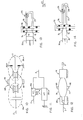
- a rotary valve 70 in replacement of the damper nnechanism 5 and its associated control.
- the valve 70 is driven in rotation by shaft 71 which extends for rotation within output shaft 3 and extends through universal joint 30 for rigid attachment to input shaft 2 to undergo rotation therewith.
- the mounting of the rotary valve 70 is illustrated in the embodiment shown in Figure 9.
- the piston 35 travels in a cylinder 36a and is sealingly mounted therein by means of seals 72.
- a pressure chamber 73 is formed whereas at the left side the cylinder 36a is open to atmospheric pressure. In other embodiments, both sides of the piston may be utilised.
- the rotary valve 70 rotates in a vertical plane at the end of chamber 73 at each of the cylinders.
- the rotary valve 70 is formed with two circumferential slots 74 and 75, each extending over an angle of slightly less than one half of the annular extent of the valve, the slot 74 being located radially outwards at a greater distance from the centre of rotation of the valve 70 as compared to the slot 75.
- the slots 74 and 75 each extend over less than one half of the annular extent of the valve 70 to provide a solid region between the slots of an extent equal to the diameter of cylinder 73 in order to prevent intercommunication between the slots during rotation of valve 70.
- the slot 74 faces an outer channel 76, while the slot 75 faces an inner channel 77.
- the rotary valve 70 confers the operation of the mechanism as an oil pump rather than as a damped clutch.
- the piston 35 undergoes one reciprocal stroke for each rotation of the valve 70.
- one of the slots 74 or 75 communicates with the chamber 73 whereas in the return stroke to the left the other slot communicates with chamber 73. In this way, a continuous path of oil flow is produced in the inner and outer channels 76 and 77.
- each chamber 73 can be provided with an output port 78 controlled by a check valve and an input port 79 controlled by a check valve 79a. The input and output ports of the chambers are connected to corresponding input and output manifolds via the respective check valves.
- FIG 9 there is seen the swash mechanism 4 connected to pistons 35 which are controlled by rotary valve 70 as described in Figures 7 and 8.
- the check valves 78a and 79a can be utilised as in Figure 7A.
- the channels 76 and 77 at the output of the valve 70 are connected to channels 76a and 77a of a rotary valve 70a similar to valve 70 and associated with a second swash mechanism 4a.
- two pump constructions 104, 104a are connected together by a hydraulic circuit 105 composed of channels 76, 76a and channels 77 and 77a.
- the circuit 105 includes, for each of the pairs of connected channels, a volumetric compensator 80 which includes a piston 81 slidably mounted in a chamber 82 containing a biassing spring 83 acting on the piston 81.
- the volumetric compensator absorbs pulsations in the pump rates.
- the swash mechanism 4a is identical in construction to that of swash mechansim 4 except that input plate 6a is secured to a frame 106 which is supported from fixed structure 107 for pivotal movement in a vertical plane passing through axis of rotation X-X.
- the pivotal movement of frame 106 takes place in grooves 108 provided in the fixed structure 107.
- Any suitable means for displacement of the frame 106 can be employed and by way of example may comprise a linkage mechanism of the type shown at 23 in Figure 1.
- the frame 106 is mounted for pivotal movement on a spherical joint 109 on output shaft 3.
- the output plate 7a of swash mechanism 4a is mounted for universal movement on spherical joint 30a.
- Ball-bearings 8a are provided between plates 6a and 7a.
- the swash mechanism 4a By pivotably moving the frame 106, the swash mechanism 4a is moved to an angular position with respect to axis X-X.
- the frame 106 is movable in opposite directions of pivotal movement as shown by the arrows 110 whereby the swash mechanism 4a may be inclined in one direction or the other for a reason to be explained later.
- the rotary valve 70a rotatably supports cylinders 36 and is fixed to the fixed structure 107.
- Swash pump 104 is effectively mounted on the output side of shaft 2 and its input is supplied by the input shaft 2.
- Swash pump 104a is connected to swash pump 104 via the hydraulic circuit 105.
- Figure 10 shows the arrangement where flow of the hydraulic fluid is from the swash pump 104 to the swash pump 104a in the cylinders located above the axis of rotation X-X while return flow takes place from swash pump 104a to swash pump 104 in the cylinders below the axis of rotation X-X.
- the swash pumps 104 and 104a are independently adjustable and hydraulic fluid will flow in the circuit 105 when there is relative rotation of the output shaft 3 with respect to the input shaft 2.
- the effective gear ratio between the input shaft 2 and the output shaft 3 may be continuously varied from one to infinity.
- the flow of hydraulic fluid is zero, both at gear ratios of one and infinity but not in between.
- the hydronamic loss H can be taken as proportional to the flow rate and is given by the following expression:
- the transmission of the invention can be utilised to obtain a reverse gearing ratio and an overdrive gear ratio, ie r is less than 1.
- a reverse gearing ratio and an overdrive gear ratio ie r is less than 1.
- One example has been shown by making the angle of swash mechanism 104a negative.
- pumps 104 and 104a have been shown as swash pumps, other types of constructions can be used such as the variable eccentric cam arrangements illustrated in Figure 4-6. Additionally, pump 104 can be of the check valve type as described with respect to Figure 7A instead of the rotary valve type for selected applications. This would give the transmission a one-directional ratchet like property. This follows from the fact that a check valve pump can act as a pump but not a motor.
- FIG. 11 shows a simplified schematic arrangement of the transmission of the invention.
- the output of each pump 104 and 104a is connected jointly to the output shaft 3.
- the pump 104 drives the motor M, which in turn drives the output shaft 3.
- the channel 76 is directly connected to the channel 77 via a one-way check valve 176.
- the valve 176 is constructed as a variable control valve, then this valve can serve as a variable damping means for the piston and thereby for variable engagement and disengagement of the clutch.
- variable control valve 138 is mounted in the circuit connecting channels 76 and 77 downstream of check valve 176.
- the control valve 138 can be of the same construction as that of rotary valve 38 for providing variable communication between cahnnels 76 and 77 and thereby variable damping of fluid flow outside cylinder 36a. This construction provides an overrun clutch with capability of variable degrees of engagement thereof.
- Figure 9A shows a modification of the construction in Figure 9 by addition of check valve 176 in channel 76.
- Check valve 176 opens when the pressure in channel 76 exceeds a predetermined value and closes when the pressure falls below this value. This provides an overrun operation in the transmission in Figure 9.
- Figure 9B shows another modification of the transmission in Figure 9 by providing pressure relief ports 130 in respective volumetric compensators 80 and channels 131 connecting each relief port of the associated compensator 80 to the other of the channels.
- the relief port 130 of the compensator 80 in channel 76 is connected by channel 131 to channel 77 whereas the relief port 130 of the compensator 80 in channel 77 is connected by channel 131 to channel 76.
- This arrangement serves as a means for limiting torque transfer in the transmission in Figure 9.
- torque transmission can also be limited in the clutch arrangement of Figure 1.
- a method and apparatus for controllably transmitting torque between the input shaft 2 and the output shaft 3 by producing reciprocal movement of pistons 35 in their respective cylinders in response to rotation of the input shaft 2 and controllably damping external circulation of the fluid from the cylinder 36 to damp the movement of the pistons 35 in their respective cylinders in response to rotation of the input shaft 2 and controllably damping external circulation of the fluid from the cylinder 36 to damp the movement of the pistons and effect rotation of the output shaft 3 in response to the degree of damping of the movement of the pistons in the cylinders.
- the pistons can travel coaxially with the shaft in the embodiment utilising the swash mechanism 4 or the pistons can travel radially in the embodiments using the eccentric cam mechanisms.
- the controlled damping of the movement of the pistons in the cylinders can be effected under the control of the swash pumps as illustrated in Figure 9 to provide a transmission whose gear ratio can go from negative to positive values including overdrive.
- variable displacement hydrostatic pumping means secured to the output shaft for producing fluid flow upon differential rotation of the input and output shafts and power control means for controlling the fluid flow by selectively absorbing or dissipating the power of the fluid flow whereby the output shaft can be driven by the input shaft with a variable degree of rotation.
- the power control means may comprise a variable displacement hydrostatic motor whose housing is mounted on fixed structure and whose output shaft is drivingly connected to the output shaft of the apparatus.
- the hydrostatic pumping means is of fixed displacement.
- hydrostatic pumping means any pumping means which converts substantially all the power of the input shaft rotation (except for frictional losses) into fluid power at all power levels including zero power at which point a constant static fluid pressure may be maintained as a function of the torque of the input shaft.
- Such hydrostatic pumping means includes piston pumps, diaphragm pumps, peristatic pumps, collapsing chamber pumps, gear pumps and the like. It excludes centrifugal pumps, turbine pumps etc.
- displacement of the pump is meant the volume of fluid pumped for the total shaft rotation angle which is equal to the ratio of the volumetric rate of flow to shaft velocity.
Abstract
Power transmission apparatus for driving an output shaft (3) from an input shaft (2) comprising a fluid cylinder (36) secured to the output shaft (3) and a piston (35) slidably mounted in the cylinder. The piston (35) is driven in reciprocal movement in the cylinder (36) in response to rotation of the input shaft (2). The movement of the piston (35) is controllably damped in the cylinder (36) to produce controlled rotation of the output shaft (3) in correspondence therewith whereby the output shaft (3) can be driven from the input shaft (2) with a variable speed of rotation. By utilising a first swash (1) mechanism to drive the piston (35) from the input shaft (2) and a second swash mechanism (4a) to control damping, a variable speed differential hydrostatic transmission is obtained.
Description
- The invention relates to a power transmission apparatus for driving an output shaft from an input shaft.
- The invention, in one arrangement, relates to power transmission apparatus which will permit selective drive of the output shaft at a variable gear ratio with respect to the input shaft.
- The invention also relates to methods of operation of such power transmission apparatus.
- The method and apparatus may, in a preferred embodiment, allow the variation of drive of the output shaft from the input shaft in a ratio which is both positive and negative.
- A wide variety of clutch and transmission mechanisms are known in which hydraulic power is employed for the drive and/or control.
- The following show examples of the wide variety of clutches and power transmissions:

- In the conventional systems, clutch engagement is effected by means of high friction surfaces which lead to high wear forces requiring frequent replacement of the friction elements. Additionally, heat is generated during engagement and disengagement of the clutch which must be dissipated. In the case of hydraulic transmissions, it is necessary to circulate a volume of hydraulic fluid at high speeds which leads to generation of heat and substantial energy losses. Moreover, the hydraulic fluid has high inertia whgich opposes rapid variations in speed change. In mechanical clutches, it is necessary to apply high force to the engaging members to hold them in engaged relation when the clutch is operative.
- Also known in the art are so-called wobble plate or swash-type drive mechanisms for hydraulica and pneumatic pumps and motors.
- Typical swash-type drive mechanisms can be found in the following patents:

- The present invention provides, according to a first aspect, apparatus for transmitting power from an input shaft having an axis of rotation to an output shaft, said apparatus comprising variable displacement pumping means secured to said output shaft and including a movable member for pumping a fluid, means connected to said input shaft for producing movement of said movable member in response to rotation of said input shaft, and means for controllably damping movement of said member to produce controlled rotation of said output shaft in correspondence therewith whereby the output shaft can be driven from the input shaft with a variable degree of rotation.
- The present invention provides, according to a further aspect, power transmitting apparatus comprising an input shaft having an axis of rotation, an input plate mounted on said input shaft for adjustable angular position relative to said axis of rotation, an output shaft, an output plate mounted for universal movement on said output shaft, means connecting said input and output plates together in coupled relation and permitting angular rotation relative to one another, means for adjusting the angular position of said input plate relative to said input shaft and thereby the angular position of the output plate therewith relative to said output shaft, and means secured to said output shaft and connected to said output plate for controllably holding the output plate in said angular position whereby the output plate becomes coupled in rotation with the input plate and said output shaft is driven in rotation.
- The present invention provides, according to a further aspect, a method of controllably transmitting torque between an input shaft and an output shaft, said method comprising producing movement of a member in a container containing an incompressible fluid in response to rotation of the input shaft, controllably damping external circulation of the fluid in said container to damp movement of said member in said container and rotating the output shaft in response to the degree of damping of the movement of said member in said container.
- The present invention provides, according to a further aspect, apparatus for transmitting power from an input shaft having an axis of rotation to an output shaft, said apparatus comprising variable displacement hydrostatic pumping means secured to said output shaft for producing fluid flow upon differential rotation of said input and output shafts, and power control means for controlling said fluid flow by selectively absorbing or dissipating the power of the fluid flow whereby the output shaft can be driven by the input shaft with a variable degree of rotation.
- The invention will be described hereafter in relation to preferred embodiments thereof given by way of example and with reference to the attached drawings in which:
- Figure 1 is a diagrammatic illustration, partly in cross-section of a first embodiment of a clutch mechanism according to the invention,
- Figure 2 is a sectional view taken on line 2-2 in Figure 1,
- Figure 3 is a diagrammatic illustration of a modification of a portion of the construction shown in Figure 1,
- Figure 4 is a diagrammatic illustration, partly in section of a modification of a portion of the clutch mechansim of Figure 1,
- Figure 5 is a sectional view taken on line 5-5 in Figure 4,
- Figure 6 is a view similar to Figure 5 of a modified embodiment.,
- Figure 7 is a diagrammatic illustration of a modification of the construction shown in Figure 1 to convert the same to a directional oil pump,
- Figure 7A diagrammatically illustrates another modification of the construction in Figure 1,
- Figure 8 is a view taken on line 8-8 in Figure 7,
- Figure 9 is a diagrammatic illustration, partly in section of a clutch mechanism serving as a variable transmission,
- Figure 9A illustrates a modification of the construction in Figure 9,
- Figure 9B illustrates another modification of the construction in Figure 9,
- Figure 10 is a schematic illustration of the transmission in Figure 9,
- Figure 11 is a simplified schematic illustration of the transmission in Figure 10,
- Figure 12 is a schematic illustration of a conventional hydrostatic transmission,
- Figure 13 diagrammatically illustrates a modification of the construction in Figure 7, and,
- Figure 14 diagrammatically illustrates another modification of the construction in Figure 7.
- Referring to Figure 1 of the drawings, therein is shown power transmitting apparatus in the form of a
clutch mechanism 1 having a variable degree of engagement between aninput shaft 2 and anoutput shaft 3. The variable degree of engagement is provided by a swash mechanism 4 and avariable damping mechanism 5 as will be explained in detail, subsequently. Theinput shaft 2 is driven in rotation from a source (not shown) around axis X-X. - The
input shaft 2 and theoutput shaft 3 are axially aligned. - The swash plate mechanism 4 comprises an
input plate 6 and a facingoutput plate 7 between which is a bearing mechansim illustrated as a ball-bearing 8 which permits relative angular rotation ofinput plates input shaft 2. Theinput plate 6 is supported on aframe 9 which is fixed to theinput shaft 2. The support of theinput plate 6 is bypivot pins 10 which are fitted inslots 11 in theframe 9 to permit theinput plate 6 to undergo pivotal movement about axis X-X. - In order to adjust the angular position of
input plate 6 with respect to theinput shaft 2, an actuator orcontrol disk 20 is spline connected to theshaft 2 such that it is coupled in rotation therewith but is capable of relative axial movement therealong. Aslide 21 which is supported on fixed structure for axial travel parallel to axis X-X straddles thedisk 20 to displace the same axially in opposite directions alonginput shaft 2. Theslide 21 is externally actuated for movement in the direction shown by the double arrows designated bynumeral 22. Thedisk 20 is connected to theinput plate 6 by alinkage mechanism 23 such that travel ofdisk 20 produces pivotal movment ofinput plate 6. - The
link mechanism 23 comprises a control rod 24 which is pivotably connected todisk 20. A pair oflocking rods rod 25 is pivotably connected to theinput shaft 2 and therod 26 carried apin 27 at its lower end which is slidable in aguide slot 28 on theinput shaft 2. Aswash rod 29 is pivotally mounted at one end onpin 27 and at the other end, therod 29 is pivotably connected toinput plate 6 at a location offset from the centre of the plate. In the position illustrated in Figure 1, the input plate extends in a plane perpendicular to the axis of rotation X-X ofinput shaft 2. In order to place the swash mechanism 4 into an angulated position, theslide 21 is displaced to the right in Figure 1 to cause thedisk 20 to slide axially on theshaft 2. This produces pivotal movement of the rod 24 and displacement ofpin 27 inslot 28 to the right end thereof. This causesswash rod 29 to pivot theinput plate 6 to an inclined position with respect to the axis X-X ofinput shaft 2. In this position, therods - The
output plate 7 of the swash mechanism is mounted on aspherical coupling 30 whose centre is concentric with the travel path ofpivot pins 10. Theoutput plate 7 is capable of undergoing universal movement on thespherical coupling 30. - A plurality of connecting
rods 31 are pivotably connected to theoutput plate 7 byball joints 32. - The connecting
rods 31 are connected byball joints 33 at their opposite ends topiston rods 34. Thepiston rods 34carry pistons 35 which are supported for reciprocal slidable movement incylinders 36 formed inhousing 37 of thedamping mechanism 5. Thepistons 35 mounted in thecylinders 36 constitute a variable displacement pumping means for a hyudraulic fluid in thehousing 37. The damping mechanism comprises arotatable valve 38 in thehousing 37. At each of its ends, thecylinder 36 is connected byports 39 with achamber 40 containing thevalve 38. As seen in Figure 2 the valve has a constructin including ariased part 41 and arecessed part 42. In the position shown, therecessed part 42 permits free communication between thecylinder 36 and thechamber 40 via theports 39. As thevalve 38 is rotated, theports 39 become progressively closed to block communication ofcylinder 36 andchamber 40. Eventually, thevalve 38 can assume a position in which theports 39 are completely blocked. - The
housing 37 is fixed to theoutput shaft 3 by aframe 43 which supports amechanism 44 for control of the angular position of thevalve 38. Themechanism 44 comprises a slider 45 which is supported on fixed structure for axial travel in the direction shown by thearrows 46 parallel to the axis of rotation X-X. Acontrol disk 47 is moved with the slider 45 and carrieshelical bushing 48 at its inner periphery which is in mesh with ahelical gear 49 rotatably carried on theoutput shaft 3. Thehelical gear 49 is secured to avalve gear 50 such that rotation ofhelical gear 49 by bushing 48 produces corresponding rotation ofgear 50.Gear 50 is in mesh withgears 51, secured torespective valves 38, such that rotation ofgear 50 produces rotation ofgears 51 andvalves 38 secured thereto. The axial travel ofcontrol disk 47 alongoutput shaft 3 is ensured by the provision of guide tracks 52 inframe 43. In this way, thecontrol disk 47 is prevented from rotating relative to theoutput shaft 3. Thegear 50 is formed withangular slots 53 which allow relative angular movement of thegear 50 with respect to theframe 43 andoutput shaft 3 in order to control the angle ofvalves 38. - In operation, in the position illustrated in Figure 1 the clutch is disengaged. In this position, the swash angle is zero and the
rotary valves 38 are each in position in itsrespective housing 37 such that theports 39 are open. Therefore, hydraulic fluid, such as oil, contained inhousing 37 is capable of freely flowing between thecylinder 36 and thechamber 40. In actuality, when the swash angle is zero there is substantially no flow of hydraulic fluid. - To engage the clutch with a minimum of stress, the
actuator 21 is displaced to the right in the drawing until the swash angle is locked at a maximum value. In this position, thepin 27 will be to the right inslot 28 and therods pistons 35 will freely displace in theircylinders 36 since theports 39 are open and the hydraulic fluid is capable of being freely displaced from thecylinder 36 into thechamber 40. To engage the clutch, the slider disk 45 is displaced in eitherdirection 46 to produce rotation ofvalves 38, whereupon theports 39 are progressively closed. When theports 39 are partially closed, heat is dissipated and the clutch is partially engaged. When theports 39 are completely closed, thepistons 35 are completely locked and the clutch is completely engaged. Thereupon, theoutput plate 7 undergoes rotation with theinput plate 6 and the entire assembly comprising theframe 43 and theoutput shaft 3 are driven in rotation with theinput shaft 2. In the condition of complete engagement of the clutch, there is no slipping or energy dissipation whatsoever. - In order to disengage the clutch, the procedure is reversed: namely, the slider disk 45 is displaced in the direction of 46 to rotate the
valves 38 and open theports 39. - Since the
pistons 35 operate in both directions of their stroke when the ports are open, there is no need to have the pistons in opposition to one another. Therefore, an odd number of pistons and cylinders can be employed and 3 or 5 piston cylinder arrangements will be operative. Of course, the greater the number of piston cylinder arrangements, the smoother will be the partial engagement of the clutch. - In the construction shown, when the clutch is disengaged there may still be some residual torque transmitted. If this is not acceptable, provision can be made to pull the
plates - The above described construction has the advantage that there is no wear due to the use of high friction surfaces during engagement. In fact, the entire clutch may be enclosed in an oil reservoir with provision to make the
slide mechanisms 21 and 45 externally accessible. - Partial engagement of the clutch can be precisely controlled.
- No energy dissipation occurs during total disengagement or total engagement.
- There is only one "restoring force" that the controls must work against and that is due to the dynamic imbalance of the swash mechanism. In this regard, the swash mechanism tends to straighten to a zero swash angle. However, balancing weights may be employed to control the imbalance, as for example, illustrated in US Patent 4 235 116. Additionally, each swash plate could be made as a hemispherical surface with provision for the necessary clearance. With this constructin, the controls will not be subjected to restoring forces and perfect balance will be obtained for all stages of relative shaft rotation. In contrast, in a friction clutch, constant pressure must be supplied to keep the friction surfaces in engagement.
- Instead of the ball-bearing 8 between the
plates input plate 6 is formed with an integral annular race 6a having opposed legs 6b and 6c. Theoutput plate 7 is formed with an annular ring 7a having a leg 7b which is inserted between the opposed legs 6b and 6c of the race 6a. Ball-bearings 8a are interposed between the legs of the ring and the race. With this arrangement, axial stresses tending to push the plates apart are resisted by the plates themselves and not on the shafts. - In the embodiment of Figure 1, the swash mechanism 4 was employed to transmit rotational motion from the
input shaft 2 into reciprocal movement of thepistons 35 in the cylinders. In the embodiments illustrated in Figures 4-6, there are shown constructions which avoid the use of the swash mechanism and rely upon a radial arrangement utilising an eccentric cam construction. - Referring particularly to Figures 4 and 5, therein it is seen that the
input shaft 2 carries aneccentric pin 60 extending axially from the shaft, on which is rotatably supported aroller 61. The roller rides in aslot 62 of ahousing 63. Fixed to thehousing 63 and extending in a radial plane, are a pair ofopposite damper arms 64 each carrying arespective piston 35 which travels incylinder 36 inrespective housing 37 of the same construction as previously described in relation to Figure 1. Therotatable valve 38 is mounted inchamber 40 and performs the function of selectively opening andclosing ports 39. The dampingmechanism 5 is mounted on theoutput shaft 3 in the same manner as in Figure 1 with the exception that theframe 43a is now of L-shape in order to take into account the vertical orientation of the damping mechanism in Figure 4 as compared to the horizontal orientation in Figure 1. Anadditional gear 65 is mounted on theframe 43a in order to transmit drive fromgear 50 to gear 51 secured to therotary valve 38. - The operation of the embodiment in Figures 4 and 5 is identical to that in the embodiment of Figure 1 with the exception that the pistons travel in a plane perpendicular to the axis of rotation X-X of
shaft 2. As theshaft 2 rotates, theroller 61 undergoes rolling movement in theslot 62 of thehousing 63, while the housing undergoes vertical reciprocation in a plane perpendicular to axis X-X. Thereby, thepistons 35 are driven reciprocally in thecylinders 36 when thevalve 38 is in a position in which theports 39 are open. When the valve is closed, the pistons are locked in the cylinders and the entire damping mechanism undergoes rotation withinput shaft 2 to cause rotation ofoutput shaft 3. The position ofpin 60 is adjustable in the input and output shafts to vary the eccentricity between zero and a maximum value to control the magnitude of displacement of thepiston 35 in thecylinder 36 for each rotation ofinput shaft 2. - In another modification, as shown in Figure 6, the pistons are arranged for reciprocal movement in the cylinders in a plane perpendicular to the axis X-X. In Figure 6, the arrangement is shown for only one piston but any number can be. used in a radial arrangement. In Figure 6, it is seen that the
shaft 2 carrieseccentric pin 60 which drives aneccentric cam 66 in revolution around the axis of rotation X-X ofshaft 2. Thecam 66 supports abearing ring 67 which is integral with a connectingrod 68 pivotably connected topiston 35. Theinput shaft 2 could be formed as a crank shaft with offset portions on which the connecting rods are mounted to transmit axial reciprocatory movement to therespective pistons 35. As in Figure 5, the degree of eccentricity betweenpivot 60 oninput shaft 2 andcam 66 is adjustable to vary the displacement of thepiston 35 for each rotation ofshaft 2. - It has been seen from the above that when the
rotary valve 38 is closed to close theports 39, thepistons 35 become locked in their respective cylinders which produces rotation ofoutput shaft 3 withinput shaft 2. The clutch construction can be provided with a torque-limiting characteristic by providing a connection between theports 39 with a pressure relief valve therein. - Although control of the damping
mechanisms 5 has been shown in conjunction with a gear arrangement including slider 45, other possibilities will be evident to those skilled in the art. Among these is the use of a centrifugal control for therotary valve 38 creating an automatic clutch which will engage with increasing intensity as the output shaft reaches t-he desired speed to produce locking of the pistons in their cylinders at a critical speed. - Referring next to Figures 7 and 8, therein is shown a
rotary valve 70 in replacement of thedamper nnechanism 5 and its associated control. Thevalve 70 is driven in rotation byshaft 71 which extends for rotation withinoutput shaft 3 and extends through universal joint 30 for rigid attachment to inputshaft 2 to undergo rotation therewith. The mounting of therotary valve 70 is illustrated in the embodiment shown in Figure 9. As seen in Figure 7, thepiston 35 travels in acylinder 36a and is sealingly mounted therein by means ofseals 72. At the right side of thepiston 35, apressure chamber 73 is formed whereas at the left side thecylinder 36a is open to atmospheric pressure. In other embodiments, both sides of the piston may be utilised. Therotary valve 70 rotates in a vertical plane at the end ofchamber 73 at each of the cylinders. Therotary valve 70 is formed with twocircumferential slots slot 74 being located radially outwards at a greater distance from the centre of rotation of thevalve 70 as compared to theslot 75. Theslots valve 70 to provide a solid region between the slots of an extent equal to the diameter ofcylinder 73 in order to prevent intercommunication between the slots during rotation ofvalve 70. - The
slot 74 faces anouter channel 76, while theslot 75 faces aninner channel 77. Therotary valve 70 confers the operation of the mechanism as an oil pump rather than as a damped clutch. In this respect, for each rotation of thevalve 70, first theouter slot 74 faceschamber 73 and theninner slot 75 faceschamber 73. Since therotary valve 70 is rotating in synchronism withshaft 2, thepiston 35 undergoes one reciprocal stroke for each rotation of thevalve 70. During a stroke to the right, one of theslots chamber 73 whereas in the return stroke to the left the other slot communicates withchamber 73. In this way, a continuous path of oil flow is produced in the inner andouter channels outer channel 76 is open to thechamber 73 during the power stroke ofpiston 35, hydraulic fluid will be pumped intochannel 76 during the power stroke and will be returned tochamber 73 viachannel 77 in the return stroke. If a one-way check valve 176 is provided in acircuit connecting channels rotary valve 70, eachchamber 73 can be provided with anoutput port 78 controlled by a check valve and aninput port 79 controlled by a check valve 79a. The input and output ports of the chambers are connected to corresponding input and output manifolds via the respective check valves. - Referring next to Figures 9 and 10, therein is seen an embodiment constituting a clutch of variable gear ratio which is tantamount to a variable hydrostatic transmission or differential hydrostatic transmission.
- In Figure 9 there is seen the swash mechanism 4 connected to
pistons 35 which are controlled byrotary valve 70 as described in Figures 7 and 8. Instead of therotary valve 70, the check valves 78a and 79a can be utilised as in Figure 7A. Thechannels valve 70 are connected tochannels 76a and 77a of a rotary valve 70a similar tovalve 70 and associated with asecond swash mechanism 4a. Effectively, twopump constructions 104, 104a are connected together by ahydraulic circuit 105 composed ofchannels channels 77 and 77a. Thecircuit 105 includes, for each of the pairs of connected channels, avolumetric compensator 80 which includes apiston 81 slidably mounted in achamber 82 containing abiassing spring 83 acting on thepiston 81. The volumetric compensator absorbs pulsations in the pump rates. - The
swash mechanism 4a is identical in construction to that of swash mechansim 4 except that input plate 6a is secured to aframe 106 which is supported fromfixed structure 107 for pivotal movement in a vertical plane passing through axis of rotation X-X. The pivotal movement offrame 106 takes place ingrooves 108 provided in the fixedstructure 107. Any suitable means for displacement of theframe 106 can be employed and by way of example may comprise a linkage mechanism of the type shown at 23 in Figure 1. Theframe 106 is mounted for pivotal movement on a spherical joint 109 onoutput shaft 3. The output plate 7a ofswash mechanism 4a is mounted for universal movement on spherical joint 30a. Ball-bearings 8a are provided between plates 6a and 7a. By pivotably moving theframe 106, theswash mechanism 4a is moved to an angular position with respect to axis X-X. Theframe 106 is movable in opposite directions of pivotal movement as shown by thearrows 110 whereby theswash mechanism 4a may be inclined in one direction or the other for a reason to be explained later. The rotary valve 70a rotatably supportscylinders 36 and is fixed to the fixedstructure 107. -
Swash pump 104 is effectively mounted on the output side ofshaft 2 and its input is supplied by theinput shaft 2. Swash pump 104a is connected toswash pump 104 via thehydraulic circuit 105. Figure 10 shows the arrangement where flow of the hydraulic fluid is from theswash pump 104 to the swash pump 104a in the cylinders located above the axis of rotation X-X while return flow takes place from swash pump 104a toswash pump 104 in the cylinders below the axis of rotation X-X. In the next half rotation of therotary valve 70 connected to inputshaft 2, the flow will be reversed and the operation is repeated successively. The swash pumps 104 and 104a are independently adjustable and hydraulic fluid will flow in thecircuit 105 when there is relative rotation of theoutput shaft 3 with respect to theinput shaft 2. - By varying the swash angles of one or both swash pumps 104 and 104a, the effective gear ratio between the
input shaft 2 and theoutput shaft 3 may be continuously varied from one to infinity. The flow of hydraulic fluid is zero, both at gear ratios of one and infinity but not in between. Thus, at gear ratios of one and infinity, there are no hydrodynamic losses as will be evident from the following analysis. Assuming: - V = speed of input shaft
- v = speed of output shaft
- δ = V-v (different speed)
- fl = oil flow rate of
swash pump 104 - f2 = flow rate of swash pump 104a (f1=f2=f) since the swash pumps are connected.
- al = a displacement parameter of swash pump 104 a2 = a displacement parameter of swash pump 104a (The displacement parameters can be considered as equivalent to the swash angles of the swash pumps)
- r = the effective gear ratio then:


- These equations define the displacement parameters which can be taken as related to the swash angles.
- Since


- Then

- The hydronamic loss H can be taken as proportional to the flow rate and is given by the following expression:

- For values of r greater than 1, the hydrodynamic loss is a maximum when the effective gear ratio r is equal to 2. This takes place when a1 = a2.
- If one considers the shcematic diagram of the conventional transmission as shown in Figure 12, therein it is seen that
input shaft 2 drivesswash pump 104 which feeds hydraulic fluid to and from a conventional hydraulic motor M viachannels output shaft 3. - Assuming the velocity of the input shaft to be V and the velocity of the output shaft to be v, then the flow rate f of
pump 104 is equal to Val and the flow rate of motor M is equal to VA2. - The gear ratio is given by the expression:

- If a2 f 0 and a1≠ 0
- Then f f 0
- A main advantage of the construction of the transmission of the invention over the conventional hydrostatic transmission is that when a2 = 0, the gear ratio is 1:1, which represents a condition of lockup of the pistons in the respective swash pumps 104 and 104a. Under these conditions, the hydrodynamic losses are zero. This makes the transmission of the invention very economical and efficient for conventional automotive use. It is a realtively simple matter to sense the speed of the shafts and the hydraulic pressures to automatically control the swash angles. This makes it particularly suitable as a system for automatic transmissions. It is further to be noted that at lockup, the only moving parts are the shaft and bearings.
- Since the transmission of the invention operates with the following parameters:


- Varying r from infinity to 1:a2 is started at a maximum value and a1 at zero (r = infinity). Then a1 is brought to a maximum whereupon, since a1 max. = a2 max., r = 2. Then a2 can be brought to zero whereupon r = 1 and f = O.
- Varying r from any gear ratio ri to 1:
- Starting with a1 = a1 max., then

- The transmission of the invention can be utilised to obtain a reverse gearing ratio and an overdrive gear ratio, ie r is less than 1. One example has been shown by making the angle of swash mechanism 104a negative.
- More generally, however, since
-

- Although
pumps 104 and 104a have been shown as swash pumps, other types of constructions can be used such as the variable eccentric cam arrangements illustrated in Figure 4-6. Additionally, pump 104 can be of the check valve type as described with respect to Figure 7A instead of the rotary valve type for selected applications. This would give the transmission a one-directional ratchet like property. This follows from the fact that a check valve pump can act as a pump but not a motor. - While the transmission has been described under the condition that the
shaft 2 serves as the input shaft to driveshaft 3 as the output shaft, the arrangement can be reversed in whichcase shaft 3 would now become the input shaft and would be associated with thenon-rotating swash mechanism 4a whereas theshaft 2 would be the output shaft and associated with the rotating swash mechanism 4. - In a generalised sense, the illustration in Fig. 11 shows a simplified schematic arrangement of the transmission of the invention. Therein, it is seen that the output of each
pump 104 and 104a is connected jointly to theoutput shaft 3. This is to be distinguished from the conventional transmission as illustrated in Figure 12 where thepump 104 drives the motor M, which in turn drives theoutput shaft 3. - In a simplified modification in Figure 13 the
channel 76 is directly connected to thechannel 77 via a one-way check valve 176. In this way the construction will operate as a simple ratchet or overrun clutch. If thevalve 176 is constructed as a variable control valve, then this valve can serve as a variable damping means for the piston and thereby for variable engagement and disengagement of the clutch. - In the modification in Figure 14, a
variable control valve 138 is mounted in thecircuit connecting channels check valve 176. Thecontrol valve 138 can be of the same construction as that ofrotary valve 38 for providing variable communication betweencahnnels cylinder 36a. This construction provides an overrun clutch with capability of variable degrees of engagement thereof. - Figure 9A shows a modification of the construction in Figure 9 by addition of
check valve 176 inchannel 76.Check valve 176 opens when the pressure inchannel 76 exceeds a predetermined value and closes when the pressure falls below this value. This provides an overrun operation in the transmission in Figure 9. - Figure 9B shows another modification of the transmission in Figure 9 by providing
pressure relief ports 130 in respectivevolumetric compensators 80 andchannels 131 connecting each relief port of the associatedcompensator 80 to the other of the channels. Thus, therelief port 130 of thecompensator 80 inchannel 76 is connected bychannel 131 to channel 77 whereas therelief port 130 of thecompensator 80 inchannel 77 is connected bychannel 131 tochannel 76. This arrangement serves as a means for limiting torque transfer in the transmission in Figure 9. In similar manner torque transmission can also be limited in the clutch arrangement of Figure 1. - In a broad sense, there is provided a method and apparatus for controllably transmitting torque between the
input shaft 2 and theoutput shaft 3 by producing reciprocal movement ofpistons 35 in their respective cylinders in response to rotation of theinput shaft 2 and controllably damping external circulation of the fluid from thecylinder 36 to damp the movement of thepistons 35 in their respective cylinders in response to rotation of theinput shaft 2 and controllably damping external circulation of the fluid from thecylinder 36 to damp the movement of the pistons and effect rotation of theoutput shaft 3 in response to the degree of damping of the movement of the pistons in the cylinders. The pistons can travel coaxially with the shaft in the embodiment utilising the swash mechanism 4 or the pistons can travel radially in the embodiments using the eccentric cam mechanisms. - The controlled damping of the movement of the pistons in the cylinders can be effected under the control of the swash pumps as illustrated in Figure 9 to provide a transmission whose gear ratio can go from negative to positive values including overdrive.
- Effectively, there is provided a variable displacement hydrostatic pumping means secured to the output shaft for producing fluid flow upon differential rotation of the input and output shafts and power control means for controlling the fluid flow by selectively absorbing or dissipating the power of the fluid flow whereby the output shaft can be driven by the input shaft with a variable degree of rotation.
- The power control means may comprise a variable displacement hydrostatic motor whose housing is mounted on fixed structure and whose output shaft is drivingly connected to the output shaft of the apparatus.
- The hydrostatic pumping means is of fixed displacement.
- By "hydrostatic pumping means" is meant any pumping means which converts substantially all the power of the input shaft rotation (except for frictional losses) into fluid power at all power levels including zero power at which point a constant static fluid pressure may be maintained as a function of the torque of the input shaft. Such hydrostatic pumping means includes piston pumps, diaphragm pumps, peristatic pumps, collapsing chamber pumps, gear pumps and the like. It excludes centrifugal pumps, turbine pumps etc.
- By "displacement" of the pump, is meant the volume of fluid pumped for the total shaft rotation angle which is equal to the ratio of the volumetric rate of flow to shaft velocity.
- Although the invention has been described in relation to specific embodiments thereof, numerous modificiations and variations will become evident to those skilled in the art without departing from the scope of the invention as defined in the attached claims.
Claims (17)
1. Apparatus for transmitting power from an input shaft having an axis of rotation to an output shaft, said apparatus comprising variable displacement pumping means secured to said output shaft and including a movable member for pumping a fluid, means connected to said input shaft for producing movement of said movable member in response to rotation of said input shaft, and means for controllably damping movement of said member to produce controlled rotation of said output shaft in correspondence therewith whereby the output shaft can be driven from the input shaft with a variable degree of rotation.
2. Apparatus as claimed in claim 1 wherein said variable displacement pumping means comprises a cylinder and said movable member comprises a piston mounted for reciprocal movement in said cylinder.
3. Apparatus as claimed in claim 2 wherein said means connected to said input shaft comprises an input plate angularly adjustable on said input shaft, an output plate universally mounted on said output shaft and coupled to said input plate, and connecting said output plate to said piston, said input plate and output plate forming a swash mechanism in which said plates can be inclined relative to the axis of rotation of said input shaft, said apparatus having a disengaged condition in which the piston is freely displaceable, without damping, in said cylinder and an engaged condition in which said input shaft and movement of said piston is damped whereupon said swash mechanism constrains said output plate to rotate and cause said cylinder to rotate around said axis of rotation of the input shaft and drive said output shaft in rotation therewith.
4. Apparatus as claimed in claim 3 wherein in a fully engaged condition of the clutch apparatus, said piston is fully damped and is stationary in said cylinder whereupon said output plate rotates together with said input plate, whereas in a partially engaged condition of the clutch apparatus the piston is partially damped and undergoes reciprocal movement in the cylinder and said output plate rotates relative to the input plate and concurrently undergoes a swash movement.
5. Apparatus as claimed in claim 4 further comprising a second output plate mounted for universal movement relative to said output shaft, a second input plate pivotably mounted on fixed structure for movement in a plane passing through said axis of rotation, said second output and input plates forming a second swash mechanism, means connecting said second input and output plates together in coupled relation for common pivotal movementn realtive to the fixed structure while permitting angular rotation relative to one another, means for adjusting the angular position of said second input plate and thereby that of said second output plate, a second cylinder secured to said output shaft for rotation therewith, a second piston slidably mounted in said second cylinder and connected to said second output plate, and means interconnecting said first and second cylinders for permitting flow of fluid therebetween.
6. Apparatus as claimed in claim 4 or 5 wherein said means which interconnects the first and second cylinders includes a volumetric compensator.
7. Apparatus as claimed in any of claims 1 to 6 comprising means for adjusting the angular position of said input plate on said input shaft.
8. Apparatus as claimed in claim 7 wherein said means for adjusting the angular positon of said input plate on said input shaft includes an actuator which is axially displaceable parallel to the axis of rotation of said input shaft, said means for controllably damping movement of said piston including a second actuator movable axially parallel to the axis of rotation of said output shaft.
9. Apparatus as claimed in claim 2, wherein said means for producing reciprocal movement of said piston comprises cam means eccentrically connected to said input shaft and connected to said piston to produce reciprocal movement of said piston upon rotation of said input shaft.
10. Apparatus as claimed in claim 9 wherein said piston is arranged to undergo reciprocal movement in a plane inclined at an angle relative to the axis of rotation of said input shaft.
11. Apparatus as claimed in claim 9 wherein said plane in which the piston undergoes movement is perpendicular to the axis of rotation of said input shaft.
12. Apparatus as claimed in claim 9, 10 or 11 wherein said cam means is adjustably connected to the input shaft to vary the eccentricity and thereby the stroke of the reciprocal movement of said piston.
13. Power transmitting apparatus as claimed in claim 1 wherein said damping means includes check valve means.
14. Apparatus. as claimed in claim 5 wherein the angular adjustment of said second input and output plates relative to the first and second input plates exceeds 90 degrees to enable the output shaft to be selectively driven in opposite directions from the input shaft.
15. Power transmitting apparatus comprising an input shaft having an axis of rotation, an input plate mounted on said input shaft for adjustable angular position relative to said axis of rotation, an output shaft, an output plate mounted for universal movement of said output shaft, means connecting said input and output plates together in coupled relation and permitting angular rotation relative to one another, means for adjusting the angular position of said input plate relative to said input shaft and thereby the angular position of the output plate therewith relative to said output shaft and means secured to said output shaft and connected to said output plate for controllably holding the output plate in said angular position whereby the output plate becomes coupled in rotation with the input plate and said output shaft is driven in rotation.
16. A method of controllably transmitting torque between an input shaft and an output shaft, said method comprising producing movement of a member in a container containing an incompresible fluid in response to rotation of the input shaft, controllably damping external circulation of the fluid in said container to damp movement of said member in said container and rotating the output shaft in response to the degree of damping of the movement of said member in said container.
17. Apparatus for transmitting power from an input shaft having an axis of rotation to an output shaft, said apparatus comprising variable displacement hydrostatic pumping means secured to said output shaft for producing fluid flow upon differential rotation of said input and output shafts, and power control means for controlling said fluid flow by selectively absorbing or dissipating the power of the fluid flow whereby the output shaft can be driven by the input shaft'with a variable degree of rotation.
Applications Claiming Priority (2)
| Application Number | Priority Date | Filing Date | Title |
|---|---|---|---|
| US43880082A | 1982-11-03 | 1982-11-03 | |
| US438800 | 1982-11-03 |
Publications (1)
| Publication Number | Publication Date |
|---|---|
| EP0108577A1 true EP0108577A1 (en) | 1984-05-16 |
Family
ID=23742070
Family Applications (1)
| Application Number | Title | Priority Date | Filing Date |
|---|---|---|---|
| EP83306594A Withdrawn EP0108577A1 (en) | 1982-11-03 | 1983-10-28 | Power transmission apparatus |
Country Status (2)
| Country | Link |
|---|---|
| EP (1) | EP0108577A1 (en) |
| JP (1) | JPS59117949A (en) |
Cited By (2)
| Publication number | Priority date | Publication date | Assignee | Title |
|---|---|---|---|---|
| WO1993013337A1 (en) * | 1991-12-23 | 1993-07-08 | DUNSTAN, Mary, E. +hf | Infinitely variable differential hydrostatic transmission |
| EP3559514A4 (en) * | 2016-12-20 | 2020-08-26 | Kinetics Drive Solutions Inc. | Hydrostatic drive system with variable vibration damper |
Families Citing this family (1)
| Publication number | Priority date | Publication date | Assignee | Title |
|---|---|---|---|---|
| JP4898491B2 (en) * | 2007-02-23 | 2012-03-14 | 三菱重工業株式会社 | Power turbine test equipment |
Citations (14)
| Publication number | Priority date | Publication date | Assignee | Title |
|---|---|---|---|---|
| US996920A (en) * | 1908-05-25 | 1911-07-04 | James H Gibson | Transmission-gear. |
| DE433450C (en) * | 1919-03-12 | 1926-08-31 | Fritz Egersdoerfer | Fluid change gearbox |
| US1613525A (en) * | 1922-03-03 | 1927-01-04 | Munro Alfred Horner | Power-transmission gear |
| US1775460A (en) * | 1928-04-05 | 1930-09-09 | Krupp Ag | Variable-speed gear |
| DE568720C (en) * | 1930-04-17 | 1933-06-22 | Boguslaw Weigle | A fluid change-speed gearbox serving as a clutch, which consists of several cylinders arranged in a star shape and whose speed control is only brought about by adjusting the eccentricity of the crank pin |
| DE622776C (en) * | 1932-02-29 | 1935-12-06 | Boguslaw Weigle | Fluid change gearbox |
| US2213616A (en) * | 1939-01-16 | 1940-09-03 | Russell D Semon | Rotary transmission or brake |
| US2231100A (en) * | 1938-05-09 | 1941-02-11 | Gunnar A Wahlmark | Fluid motor and pump |
| DE1051602B (en) * | 1955-10-05 | 1959-02-26 | Daimler Benz Ag | Lubrication for the control surfaces of hydrostatic gears |
| FR1338998A (en) * | 1962-08-24 | 1963-10-04 | Automatic speed variator | |
| DE1500480A1 (en) * | 1965-05-12 | 1969-07-10 | Rheinstahl Henschel Ag | Hydrostatic transmission |
| DE2050944A1 (en) * | 1969-10-17 | 1971-04-29 | Citroen Sa | Hydrostatic transmission |
| US3620130A (en) * | 1969-06-30 | 1971-11-16 | Borg Warner | Hydrostatic transmission mechanism |
| DE2203478A1 (en) * | 1972-01-26 | 1973-08-02 | Kopat Ges Fuer Konstruktion En | HYDROSTATIC TORQUE CONVERTER |
-
1983
- 1983-10-28 EP EP83306594A patent/EP0108577A1/en not_active Withdrawn
- 1983-11-02 JP JP58205012A patent/JPS59117949A/en active Pending
Patent Citations (14)
| Publication number | Priority date | Publication date | Assignee | Title |
|---|---|---|---|---|
| US996920A (en) * | 1908-05-25 | 1911-07-04 | James H Gibson | Transmission-gear. |
| DE433450C (en) * | 1919-03-12 | 1926-08-31 | Fritz Egersdoerfer | Fluid change gearbox |
| US1613525A (en) * | 1922-03-03 | 1927-01-04 | Munro Alfred Horner | Power-transmission gear |
| US1775460A (en) * | 1928-04-05 | 1930-09-09 | Krupp Ag | Variable-speed gear |
| DE568720C (en) * | 1930-04-17 | 1933-06-22 | Boguslaw Weigle | A fluid change-speed gearbox serving as a clutch, which consists of several cylinders arranged in a star shape and whose speed control is only brought about by adjusting the eccentricity of the crank pin |
| DE622776C (en) * | 1932-02-29 | 1935-12-06 | Boguslaw Weigle | Fluid change gearbox |
| US2231100A (en) * | 1938-05-09 | 1941-02-11 | Gunnar A Wahlmark | Fluid motor and pump |
| US2213616A (en) * | 1939-01-16 | 1940-09-03 | Russell D Semon | Rotary transmission or brake |
| DE1051602B (en) * | 1955-10-05 | 1959-02-26 | Daimler Benz Ag | Lubrication for the control surfaces of hydrostatic gears |
| FR1338998A (en) * | 1962-08-24 | 1963-10-04 | Automatic speed variator | |
| DE1500480A1 (en) * | 1965-05-12 | 1969-07-10 | Rheinstahl Henschel Ag | Hydrostatic transmission |
| US3620130A (en) * | 1969-06-30 | 1971-11-16 | Borg Warner | Hydrostatic transmission mechanism |
| DE2050944A1 (en) * | 1969-10-17 | 1971-04-29 | Citroen Sa | Hydrostatic transmission |
| DE2203478A1 (en) * | 1972-01-26 | 1973-08-02 | Kopat Ges Fuer Konstruktion En | HYDROSTATIC TORQUE CONVERTER |
Cited By (2)
| Publication number | Priority date | Publication date | Assignee | Title |
|---|---|---|---|---|
| WO1993013337A1 (en) * | 1991-12-23 | 1993-07-08 | DUNSTAN, Mary, E. +hf | Infinitely variable differential hydrostatic transmission |
| EP3559514A4 (en) * | 2016-12-20 | 2020-08-26 | Kinetics Drive Solutions Inc. | Hydrostatic drive system with variable vibration damper |
Also Published As
| Publication number | Publication date |
|---|---|
| JPS59117949A (en) | 1984-07-07 |
Similar Documents
| Publication | Publication Date | Title |
|---|---|---|
| CA1293671C (en) | Continuously variable transmission including clutch valve means | |
| US4493189A (en) | Differential flow hydraulic transmission | |
| US5493862A (en) | Continuously variable hydrostatic transmission | |
| US5678405A (en) | Continuously variable hydrostatic transmission | |
| US5205123A (en) | Infinitely variable differential hydrostatic transmission | |
| JP3566728B2 (en) | Continuously variable hydraulic transmission with transmission ratio controller actuating components integrated into output shaft | |
| US4372116A (en) | Stirling engine control mechanism and method | |
| KR100578430B1 (en) | Continuously variable hydrostatic transmission including 1:1 ratio lock-up clutch | |
| JPS63150475A (en) | Shoe structure of swash plate type hydraulic device | |
| US5022310A (en) | Fluid power transmission | |
| US4075843A (en) | Hydraulic transmission | |
| JP3566729B2 (en) | Improved transmission ratio controller for continuously variable hydraulic transmission | |
| JPH02113168A (en) | Control device for static oil pressure type continuous variable transmission | |
| EP0108577A1 (en) | Power transmission apparatus | |
| US6571554B2 (en) | Hydrostatic transmission having hydraulic dampening and neutral bleed mechanism | |
| JPS62224769A (en) | Static hydraulic type continuously variable transmission | |
| RU2012836C1 (en) | Differential transmission | |
| CA1066091A (en) | Variable speed transmission device | |
| JPS62224768A (en) | Static hydraulic type continuously variable transmission |
Legal Events
| Date | Code | Title | Description |
|---|---|---|---|
| PUAI | Public reference made under article 153(3) epc to a published international application that has entered the european phase |
Free format text: ORIGINAL CODE: 0009012 |
|
| AK | Designated contracting states |
Designated state(s): BE DE FR GB IT SE |
|
| STAA | Information on the status of an ep patent application or granted ep patent |
Free format text: STATUS: THE APPLICATION IS DEEMED TO BE WITHDRAWN |
|
| 18D | Application deemed to be withdrawn |
Effective date: 19850117 |