US6571554B2 - Hydrostatic transmission having hydraulic dampening and neutral bleed mechanism - Google Patents
Hydrostatic transmission having hydraulic dampening and neutral bleed mechanism Download PDFInfo
- Publication number
- US6571554B2 US6571554B2 US09/842,340 US84234001A US6571554B2 US 6571554 B2 US6571554 B2 US 6571554B2 US 84234001 A US84234001 A US 84234001A US 6571554 B2 US6571554 B2 US 6571554B2
- Authority
- US
- United States
- Prior art keywords
- fluid
- pump
- passage
- annular element
- displacement rate
- Prior art date
- Legal status (The legal status is an assumption and is not a legal conclusion. Google has not performed a legal analysis and makes no representation as to the accuracy of the status listed.)
- Expired - Fee Related
Links
- 230000002706 hydrostatic effect Effects 0.000 title claims abstract description 60
- 230000005540 biological transmission Effects 0.000 title claims abstract description 58
- 230000007935 neutral effect Effects 0.000 title claims description 48
- 230000007246 mechanism Effects 0.000 title description 27
- 239000012530 fluid Substances 0.000 claims abstract description 175
- 238000006073 displacement reaction Methods 0.000 claims abstract description 75
- 238000004891 communication Methods 0.000 claims abstract description 42
- 239000011800 void material Substances 0.000 claims abstract description 23
- 230000033001 locomotion Effects 0.000 claims description 21
- 230000002441 reversible effect Effects 0.000 claims description 16
- 230000004044 response Effects 0.000 claims description 10
- 238000000034 method Methods 0.000 claims description 5
- 230000003247 decreasing effect Effects 0.000 claims description 3
- 238000013459 approach Methods 0.000 description 4
- 230000008859 change Effects 0.000 description 3
- 230000009471 action Effects 0.000 description 2
- 230000008901 benefit Effects 0.000 description 2
- 230000000740 bleeding effect Effects 0.000 description 2
- 230000006835 compression Effects 0.000 description 2
- 238000007906 compression Methods 0.000 description 2
- 238000013016 damping Methods 0.000 description 2
- 238000013461 design Methods 0.000 description 2
- 230000000694 effects Effects 0.000 description 2
- 230000006978 adaptation Effects 0.000 description 1
- 230000004075 alteration Effects 0.000 description 1
- 238000002485 combustion reaction Methods 0.000 description 1
- 230000000670 limiting effect Effects 0.000 description 1
- 238000012986 modification Methods 0.000 description 1
- 230000004048 modification Effects 0.000 description 1
- 230000001737 promoting effect Effects 0.000 description 1
- 230000009467 reduction Effects 0.000 description 1
- 230000002829 reductive effect Effects 0.000 description 1
- 230000000717 retained effect Effects 0.000 description 1
- 238000012546 transfer Methods 0.000 description 1
- 230000007704 transition Effects 0.000 description 1
Images


Classifications
-
- F—MECHANICAL ENGINEERING; LIGHTING; HEATING; WEAPONS; BLASTING
- F16—ENGINEERING ELEMENTS AND UNITS; GENERAL MEASURES FOR PRODUCING AND MAINTAINING EFFECTIVE FUNCTIONING OF MACHINES OR INSTALLATIONS; THERMAL INSULATION IN GENERAL
- F16H—GEARING
- F16H61/00—Control functions within control units of change-speed- or reversing-gearings for conveying rotary motion ; Control of exclusively fluid gearing, friction gearing, gearings with endless flexible members or other particular types of gearing
- F16H61/38—Control of exclusively fluid gearing
- F16H61/40—Control of exclusively fluid gearing hydrostatic
- F16H61/42—Control of exclusively fluid gearing hydrostatic involving adjustment of a pump or motor with adjustable output or capacity
- F16H61/437—Pump capacity control by mechanical control means, e.g. by levers or pedals
-
- B—PERFORMING OPERATIONS; TRANSPORTING
- B60—VEHICLES IN GENERAL
- B60K—ARRANGEMENT OR MOUNTING OF PROPULSION UNITS OR OF TRANSMISSIONS IN VEHICLES; ARRANGEMENT OR MOUNTING OF PLURAL DIVERSE PRIME-MOVERS IN VEHICLES; AUXILIARY DRIVES FOR VEHICLES; INSTRUMENTATION OR DASHBOARDS FOR VEHICLES; ARRANGEMENTS IN CONNECTION WITH COOLING, AIR INTAKE, GAS EXHAUST OR FUEL SUPPLY OF PROPULSION UNITS IN VEHICLES
- B60K17/00—Arrangement or mounting of transmissions in vehicles
- B60K17/04—Arrangement or mounting of transmissions in vehicles characterised by arrangement, location or kind of gearing
- B60K17/10—Arrangement or mounting of transmissions in vehicles characterised by arrangement, location or kind of gearing of fluid gearing
- B60K17/105—Units comprising at least a part of the gearing and a torque-transmitting axle, e.g. transaxles
-
- F—MECHANICAL ENGINEERING; LIGHTING; HEATING; WEAPONS; BLASTING
- F16—ENGINEERING ELEMENTS AND UNITS; GENERAL MEASURES FOR PRODUCING AND MAINTAINING EFFECTIVE FUNCTIONING OF MACHINES OR INSTALLATIONS; THERMAL INSULATION IN GENERAL
- F16H—GEARING
- F16H39/00—Rotary fluid gearing using pumps and motors of the volumetric type, i.e. passing a predetermined volume of fluid per revolution
- F16H39/04—Rotary fluid gearing using pumps and motors of the volumetric type, i.e. passing a predetermined volume of fluid per revolution with liquid motor and pump combined in one unit
- F16H39/06—Rotary fluid gearing using pumps and motors of the volumetric type, i.e. passing a predetermined volume of fluid per revolution with liquid motor and pump combined in one unit pump and motor being of the same type
- F16H39/08—Rotary fluid gearing using pumps and motors of the volumetric type, i.e. passing a predetermined volume of fluid per revolution with liquid motor and pump combined in one unit pump and motor being of the same type each with one main shaft and provided with pistons reciprocating in cylinders
- F16H39/10—Rotary fluid gearing using pumps and motors of the volumetric type, i.e. passing a predetermined volume of fluid per revolution with liquid motor and pump combined in one unit pump and motor being of the same type each with one main shaft and provided with pistons reciprocating in cylinders with cylinders arranged around, and parallel or approximately parallel to the main axis of the gearing
- F16H39/14—Rotary fluid gearing using pumps and motors of the volumetric type, i.e. passing a predetermined volume of fluid per revolution with liquid motor and pump combined in one unit pump and motor being of the same type each with one main shaft and provided with pistons reciprocating in cylinders with cylinders arranged around, and parallel or approximately parallel to the main axis of the gearing with cylinders carried in rotary cylinder blocks or cylinder-bearing members
-
- F—MECHANICAL ENGINEERING; LIGHTING; HEATING; WEAPONS; BLASTING
- F16—ENGINEERING ELEMENTS AND UNITS; GENERAL MEASURES FOR PRODUCING AND MAINTAINING EFFECTIVE FUNCTIONING OF MACHINES OR INSTALLATIONS; THERMAL INSULATION IN GENERAL
- F16H—GEARING
- F16H61/00—Control functions within control units of change-speed- or reversing-gearings for conveying rotary motion ; Control of exclusively fluid gearing, friction gearing, gearings with endless flexible members or other particular types of gearing
- F16H61/38—Control of exclusively fluid gearing
- F16H61/40—Control of exclusively fluid gearing hydrostatic
- F16H61/4043—Control of a bypass valve
-
- B—PERFORMING OPERATIONS; TRANSPORTING
- B60—VEHICLES IN GENERAL
- B60Y—INDEXING SCHEME RELATING TO ASPECTS CROSS-CUTTING VEHICLE TECHNOLOGY
- B60Y2200/00—Type of vehicle
- B60Y2200/20—Off-Road Vehicles
- B60Y2200/22—Agricultural vehicles
- B60Y2200/223—Ridable lawn mowers
Definitions
- the present invention relates to hydrostatic transmissions intended primarily for use in the lawn and garden industry on tractors, riding lawnmowers, lawn and garden implements and the like.
- Hydrostatic transmissions transmit rotary mechanical motion, typically from an internal combustion engine, to fluid motion, typically via positive displacement pumps and motors using oil, and then back to rotary mechanical motion to rotate a drive axle in order to drive the vehicle.
- the hydrostatic transmission controls the output rotary mechanical motion such that varying output speeds in the forward and reverse directions are possible with a single speed input rotary mechanical motion.
- Such transmissions have utilized radial piston pumps and motors, axial piston pumps and motors and hybrid transmissions wherein the pump may be of one piston design, and the motor of another.
- the speed of the output of the transmission is typically controlled by varying the eccentricity of the pump track ring of a radial piston pump or the swash plate angle of an axial piston pump.
- Hydrostatic transmissions have an inherent problem of not achieving, when placed in neutral, a condition in which the pump displacement is completely eliminated. Although the operator may shift the implement into neutral, thereby causing the hydrostatic transmission to be placed in neutral, there may still be some motion, or “creep”, of the implement. During forward or reverse operation of the hydrostatic transmission, this fluid is constantly moving through the system. In neutral, ideally, the displacement of the rotating pump is zero, and no fluid flows to the motor therefrom. Thus, no motion, however slight, is imparted to the axle. Should the rotating pump still have some slight displacement in neutral, fluid in one side of the hydrostatic system will become or remain slightly pressurized and cause the motor to slowly rotate, thereby creating forward or reverse motion of the wheels. What would be desirable is a hydrostatic transmission which allows any fluid displaced by the pump to be vented out of the hydrostatic system when the hydrostatic transmission is placed in the neutral position, thereby eliminating creep.
- hydrostatic transmission which includes a mechanism for dampening the response of the motor to changes in pump displacement rates as the pump approaches and leaves neutral so that such jerking would be eliminated.
- An advantage provided by the present invention is that any fluid displaced by the pump in neutral is vented out of the hydrostatic system, thereby preventing the occurrence of creep in the forward or reverse direction.
- An additional advantage provided by the present invention is that it dampens the effect of changes in pump displacement to and from zero by allowing a portion of the hydrostatic fluid to bleed or be vented out of the hydrostatic system as the transmission is shifted from neutral to an operative condition in forward or reverse, and vice versa.
- the present invention provides a hydrostatic transmission including a fluid motor, a variable displacement fluid pump in fluid communication with the fluid motor, the pump having first fluid displacement rate and a second fluid displacement rate, the second fluid displacement rate being much greater than the first displacement rate, a block on which the pump is mounted and having a cylindrical surface, the block provided with at least one fluid passage, fluid which flows from the pump to the motor being flowed through the passage, the block provided with at least one fluid bleed hole extending from the fluid passage to the cylindrical surface of the block, a fluid sump external to the block, and an annular element disposed about and in sliding contact with the cylindrical block surface, the annular element provided with at least one void and having a first position in which the void is in fluid communication with the fluid passage through the fluid bleed hole, and a second position in which the void is substantially out of fluid communication with the fluid passage.
- the fluid passage and the sump are in fluid communication through the bleed hole and the void when the pump is operating at its first displacement rate and the annular element is in its first position, and the fluid bleed hole and the sump are substantially out of fluid communication when the pump is operating at its second displacement rate and the annular element is in its second position.
- the present invention further provides a hydrostatic transmission including a fluid motor, a variable displacement fluid pump in fluid communication with the fluid motor, the pump having first fluid displacement rate and a second fluid displacement rate, the second fluid displacement rate being much greater than the first displacement rate, a block on which the pump is mounted, the block having a flat surface against which the pump is slidably engaged when the pump is operating at its first and second fluid displacement rates, the block provided at least one fluid passage which opens to the flat block surface, fluid which flows from the pump to the motor being flowed through the passage, a fluid sump external to the block, and means for placing the passage and the sump in fluid communication when the pump is operating at its first fluid displacement rate and providing a gradual motor response to changes between the pump first and second fluid displacement rates.
- the present invention also provides a method for dampening the response of a fluid motor to changes in a fluid pump between neutral and drive positions in a hydrostatic transmission, and ensuring that no fluid is pumped by the pump to the motor in the pump neutral position, including: rotating the pump while maintaining its sliding engagement against a block having a passage therethrough; operating the rotating pump at a first displacement rate in its neutral position, in which the passage and a sump are in fluid communication, whereby fluid displaced by the pump in its neutral position is directed to the sump; gradually decreasing the fluid communication between the passage and the sump while changing from the pump neutral position to the pump drive position; operating the rotating pump at a second displacement rate greater than the first displacement rate in its drive position, in which the passage and the sump are substantially out of fluid communication, whereby fluid displaced by the pump in its drive position is directed to the motor through the passage for driving the motor; and gradually increasing the fluid communication between the passage and the sump while changing from the pump drive position to the pump neutral position.
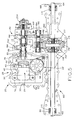
- FIG. 1 is a sectional top view of one embodiment of a reversible hydrostatic transmission module according to the present invention
- FIG. 2 is a sectional side view of the hydrostatic transmission module of FIG. 1 along line 2 — 2 thereof;
- FIG. 3 is a sectional side view of the hydrostatic transmission module of FIG. 1 along line 3 — 3 thereof;
- FIG. 4 is a side view of the hydrostatic transmission module of FIG. 1 along line 4 — 4 thereof;
- FIG. 5 is a sectional top view of the hydrostatic transmission module of FIG. 1 attached to one embodiment of a differential axle unit, the assembly forming one embodiment of hydrostatic transaxle;
- FIG. 6A is a top view of the center section or block for the hydrostatic transmission module of FIG. 1, showing a first embodiment of the inventive hydrostatic dampening and neutral bleed mechanism;
- FIG. 6B is an enlarged, fragmentary view of the center section or block of FIG. 6A, showing in section the inventive mechanism in a fully neutral position;
- FIG. 6C is an enlarged, fragmentary view of the center section or block of FIG. 6A, showing in section the inventive mechanism in a fully engaged, forward position;
- FIG. 6D is an enlarged, fragmentary view of the center section or block of FIG. 6A, showing in section the inventive mechanism in a dampened, reverse position;
- FIG. 7A is an upper perspective view of the center section or block, and the inventive mechanism of FIG. 6A, also showing the control device for the mechanism;
- FIG. 7B is an upper perspective view of a hydrostatic transmission center section or block and a second embodiment of the dampening and neutral bleed mechanism, also showing the control device for the mechanism;
- FIG. 8A is another upper perspective view of the center section or block, mechanism and control device of FIG. 7A;
- FIG. 8B is another upper perspective view of the center section or block, mechanism and control device of FIG. 7B;
- FIG. 9A is a side view of the center section or block, mechanism and control device of FIG. 7A.
- FIG. 9B is a side view of the center section or block, mechanism and control device of FIG. 7 B.
- transaxle 160 comprises hydrostatic transmission 20 and axle mechanism 180 .
- Axle mechanism 180 includes casing 166 having upper and lower halves, split along a horizontal plane coincident with the axes of axles 162 and 164 . Disposed within casing 166 are reduction gear train 188 and differential mechanism 172 . Axles 162 and 164 extend outwardly from differential mechanism 172 through a pair of openings in either end of casing 166 at which point axles 162 and 164 are sealed by seals 168 and supported by bearings 170 .
- Differential mechanism 172 is of a type known in the art and includes ring gear 174 , bevel gears 177 and 178 , and pin 176 . Differential 172 is connected to pinion 186 which is splined to countershaft 184 . The opposite end of countershaft 184 is similarly splined to gear 182 which is enmeshed with pinion gear 190 splined to gear train input shaft 194 .
- transaxle 160 is space 198 which contains mechanical disconnect mechanism 200 of the type disclosed in U.S. Pat. No. 5,701,738, issued Dec. 30, 1997, and assigned to the assignee of the present application. The disclosure of this patent is expressly incorporated herein by reference. Additionally, transaxle 160 includes brake mechanism 204 . The operation of the brake itself is the subject of U.S. Pat. No. 6,123,182, issued Sep. 26, 2000, and assigned to the assignee of the present application. The disclosure of this patent is expressly incorporated herein by reference. Transaxle 160 is further connected to hydrostatic transmission 20 , as described hereinbelow.
- hydrostatic transmission 20 comprises a separate, self-contained casing 28 having two casing halves 30 and 74 split along horizontal interface 82 which is coplanar with the axis of motor output shaft 26 .
- Casing halves 30 and 74 are connected together by a plurality of bolts 76 extending through lower casing half 74 and threadedly received in bores provided in upper casing half 30 .
- hydrostatic pump and motor mechanism 34 comprising center section, or block, 32 having pump mounting surface 128 and motor mounting surface 36 and internal passages 126 and 234 (FIG. 6A) hydraulically connecting each of arcuate slots 236 and 240 (FIG. 6A) in pump face 128 and motor mounting face 36 .
- Pump and motor mechanism 34 further includes axial piston motor 24 and variable displacement pump 22 .
- Axial piston motor 24 comprises rotatable cylinder 42 having a plurality of pistons 40 therein sliding against fixed swash plate assembly 54 and thrust bearing 52 . Face 44 of rotatable cylinder 42 interfaces with motor mounting face 36 of center section 32 .
- Motor output shaft 26 extends through cylinder 42 and is supported by bearings 48 in center section 32 . The axis of output shaft 26 is oriented 90° relative to the axis of pump input shaft 84 , as shown in FIG. 3 .
- Motor output shaft 26 is also supported by sleeve and bearing assembly 56 , particularly sleeve 58 , press fitted to casing 28 and extending through portion 62 into a recess in axle casing 166 .
- Transmission casing 28 is mounted to transaxle casing 166 at two locations 38 and 60 by corresponding overlapping extensions on casings 28 and 166 and bolts (not shown) which are driven from the bottom.
- pump 22 is in mechanical communication with pump swash plate assembly 98 , particularly swash plate 90 .
- Swash plate assembly 98 includes swash plate 90 , bearings 106 , and bearing housing plates 112 and 114 encasing bearings 106 .
- Swash plate 90 further includes arcuate bearing strips 92 with inner surfaces 94 attached to arcuate swash plate upper surface 88 and outer surface 96 interfacing with upper casing half 30 .
- Pump swash plate assembly 98 will be tilted through the action of control rod 138 and control arm 142 (FIG. 5) in order to vary the displacement of pump 22 .
- the operation of transmission 20 is more fully described hereinbelow.
- Pump 22 includes pump cylinder 116 rotatably driven by input shaft 84 and having a plurality of cylinders 68 within which are disposed pistons 80 . Pistons 80 are urged against the face of swash plate 90 by springs 110 . Shaft 84 is sealed by seal 86 and is rotatably supported by bearings 78 . Note that pump shaft 84 extends through swash plate assembly 98 and is splined to pump cylinder 116 via splined portion 108 on shaft 84 and splined portion 118 on pump cylinder 116 . Distal end 120 of shaft 84 is supported by bearing 122 in center section 32 . Screws 76 connect center section 32 to upper casing half 30 . Also located on upper casing half 30 is neutral switch 150 .
- shift lever 136 is attached to rotatable control arm 142 by screw 130 , external of casing 166 , received in control rod 138 .
- Shift lever 136 is returned to neutral by a conventional return-to-neutral spring mechanism 134 , while adjustable plate 132 permits fine adjustment of neutral position.
- Control arm 142 is attached to control rod 138 and includes first end 143 extending into arm 104 and second end 145 extending in the opposite direction; both ends 143 and 145 are perpendicular to control rod 138 .
- Second end 145 of control arm 142 swings through an arc about control rod 138 when shift lever 136 is rotated.
- Pin 144 attaches to second end 145 of control arm 142 and extends into slot 148 disposed on periphery 140 (FIG. 3) of swash plate 90 .
- Friction roller 146 fits over pin 144 and freely rotates about pin 144 to engage with slot 148 of swash plate 90 .
- Selectively positioning control arm 142 causes swash plate 90 to tilt, and in turn, pistons 80 , orbiting about input shaft 84 , reciprocate causing hydrostatic fluid in each cylinder 68 to pressurize as respective piston 80 retracts.
- Swash plate 90 tilts and rotates against a pair of low friction bearings attached to the casing as previously described.
- lower surface 124 of center section 32 is provided with a pair of openings 238 to provide makeup oil to pump 22 .
- a filter and check valves (not shown) are provided as is customary in the art for controlling the ingress and quality of the make-up oil.
- Pump input shaft 84 is received within bore 242 and integral bosses 50 of center section 32 accommodate and provide support for mounting screws 76 .
- Blind drilled passageways 126 and 234 are sealed by plugs 232 .
- annular element 100 having a ring structure.
- Annular element 100 includes protrusion 244 containing slot 102 for receipt of arm 104 .
- Arm 104 is allowed limited rotation due to its combination with control arm 142 .
- Element 100 in addition to protrusion 244 and slot 102 , further includes a pair of voids 220 extending from inner surface 101 of element 100 to outer surface 103 thereof.
- Inner surface 101 is in sliding contact with cylindrical outer surface 129 of pump mounting face 128 .
- Cylindrical surface 129 includes a pair of fluid bleed holes 222 extending from arcuate slots 236 and 240 .
- arcuate slots 236 and 240 are in fluid communication with a pair of openings in lower surface 124 of center section 32 and internal passages 234 and 126 .
- Center section 32 also includes bearing cradle 224 having raised shoulder 226 (FIG. 6 A).
- bearing cradle 224 is disclosed in U.S. patent application Ser. No. 09/498,692, filed Feb. 7, 2000, the complete disclosure of which is incorporated herein by reference.
- Arm 104 which may be an extension of control arm 142 , moves annular element 100 to a position in which voids 220 and fluid bleed holes 222 are radially aligned, thereby allowing the motive fluid to vent from the hydrostatic fluid circuit to the interior of casing 28 when transmission 20 is in neutral.
- control arm 142 has first end 143 , which is the end attached to control rod 138 and which extends to form arm 104 . If annular element 100 were not present, control arm 142 would terminate at first end 143 at the point of connection to control rod 138 , as opposed to extending beyond the connection point to form arm 104 .
- Arm 104 is operatively connected to annular element 100 at slot 102 . Arm 104 is in fitted engagement with slot 102 such that when arm 104 moves, annular element 100 rotates around cylindrical surface 129 of pump mounting surface 128 .
- a second embodiment shown in FIGS. 7B, 8 B, and 9 B, utilizes a protrusion 244 on annular element 100 ′, as does the first embodiment, but includes gear teeth 248 which are intermeshed with gear teeth 250 on arm 246 .
- Arm 246 like arm 104 , is connected to control arm 142 , and may even be an extension thereof, the operation of arm 246 is similar to that of arm 104 with shift lever 136 through control arm 142 moving arm 246 into the neutral, forward, or reverse positions. The difference is that enmeshed gear teeth 248 and 250 provide operative engagement between arm 246 and element 100 ′, versus an end of arm 104 being received in slot 102 of annular element 100 .
- pump cylinder barrel 116 is driven by a power source through input shaft 84 .
- input shaft 84 includes a first end keyed to common hub 252 of pulley 70 and fan 72 with pulley 70 being belt driven by a power source (not shown), thereby providing power to input shaft 84 .
- the other end of input shaft 84 includes splined portion 108 disposed on the surface of input shaft 84 and engages matching splined portion 118 formed within pump cylinder barrel 116 .
- Swash plate 90 selectively controlled by shift lever 136 , which is external to transmission casing 28 , initiates motive fluid displacement within pump cylinder barrel 116 to transfer power from input shaft 84 to drive axles 162 , 164 .
- control arm 142 moves in an opposite direction, thereby causing swash plate 90 to pivot in a direction corresponding to that of shift lever 136 .
- arm 104 is moved in the same direction as shift lever 136 , thereby moving annular element 100 through the operative connection at slot 102 .
- This motion allows voids 220 to either become radially aligned with fluid bleed holes 222 or to move out of radial alignment, depending upon whether the operator is selecting a neutral position, or a forward or reverse drive position.
- arm 104 causes annular element 100 to move in such a manner that voids 220 and fluid bleed holes 222 are in complete alignment, thereby allowing any motive fluid being displaced by pump 22 to bleed from center section 32 to the oil sump.
- annular element 100 is moved to a position in which voids 220 and fluid bleed holes 222 are not in alignment, thereby preventing motive fluid being displaced by the pump from being vented into the fluid sump, as shown in FIG. 6 C.
- voids 220 and holes 222 are not in alignment, as shown in FIG. 6 D.
Landscapes
- Engineering & Computer Science (AREA)
- General Engineering & Computer Science (AREA)
- Mechanical Engineering (AREA)
- Chemical & Material Sciences (AREA)
- Combustion & Propulsion (AREA)
- Transportation (AREA)
- Reciprocating Pumps (AREA)
- Control Of Fluid Gearings (AREA)
Abstract
Description
Claims (24)
Priority Applications (3)
| Application Number | Priority Date | Filing Date | Title |
|---|---|---|---|
| US09/842,340 US6571554B2 (en) | 2001-04-25 | 2001-04-25 | Hydrostatic transmission having hydraulic dampening and neutral bleed mechanism |
| CA002383680A CA2383680A1 (en) | 2001-04-25 | 2002-04-24 | Hydrostatic transmission having hydraulic dampening and neutral bleed mechanism |
| EP02009124A EP1253039A3 (en) | 2001-04-25 | 2002-04-24 | Hydrostatic transmission having hydraulic dampening and neutral bleed mechanism |
Applications Claiming Priority (1)
| Application Number | Priority Date | Filing Date | Title |
|---|---|---|---|
| US09/842,340 US6571554B2 (en) | 2001-04-25 | 2001-04-25 | Hydrostatic transmission having hydraulic dampening and neutral bleed mechanism |
Publications (2)
| Publication Number | Publication Date |
|---|---|
| US20020157392A1 US20020157392A1 (en) | 2002-10-31 |
| US6571554B2 true US6571554B2 (en) | 2003-06-03 |
Family
ID=25287099
Family Applications (1)
| Application Number | Title | Priority Date | Filing Date |
|---|---|---|---|
| US09/842,340 Expired - Fee Related US6571554B2 (en) | 2001-04-25 | 2001-04-25 | Hydrostatic transmission having hydraulic dampening and neutral bleed mechanism |
Country Status (3)
| Country | Link |
|---|---|
| US (1) | US6571554B2 (en) |
| EP (1) | EP1253039A3 (en) |
| CA (1) | CA2383680A1 (en) |
Cited By (3)
| Publication number | Priority date | Publication date | Assignee | Title |
|---|---|---|---|---|
| US20020174651A1 (en) * | 2001-05-24 | 2002-11-28 | Boyer Scott G. | Electronically controlled dampener for hydrostatic transmission |
| US20040123594A1 (en) * | 2002-12-30 | 2004-07-01 | Williams Douglas G. | Hydrostatic transmission having a hydraulic dampening and neutral bleed mechanism |
| US8109747B1 (en) | 2007-12-17 | 2012-02-07 | Hydro-Gear Limited Partnership | Drive system having a variable output gerotor pump |
Families Citing this family (2)
| Publication number | Priority date | Publication date | Assignee | Title |
|---|---|---|---|---|
| DE10329469B4 (en) * | 2003-07-01 | 2005-08-04 | Ampler, Klaus | Method and device for converting a linear movement into a rotary movement |
| US9677653B1 (en) * | 2014-10-23 | 2017-06-13 | Hydro-Gear Limited Partnership | Modular drive unit |
Citations (11)
| Publication number | Priority date | Publication date | Assignee | Title |
|---|---|---|---|---|
| US3020890A (en) | 1959-07-20 | 1962-02-13 | Oilgear Co | Pump control valve with bypass |
| US3132486A (en) * | 1959-09-15 | 1964-05-12 | Lely Nv C Van Der | Hydraulically operated power transmission systems and vehicles incorporating such systems |
| US3831497A (en) | 1972-03-22 | 1974-08-27 | Eaton Corp | Hydrostatic transmission |
| US4063608A (en) | 1974-11-25 | 1977-12-20 | Sullivan Patrick D | Hydrostatic drive vehicle |
| US4968227A (en) | 1989-12-11 | 1990-11-06 | Eaton Corporation | Variable displacement fluid pump with improved wideband neutral |
| US5235810A (en) * | 1992-09-28 | 1993-08-17 | Tecumseh Products Company | Conduit valve providing wide neutral in a hydrostatic transmission |
| US5333451A (en) | 1992-04-24 | 1994-08-02 | Kanzaki Kokyukoki Mfg. Co., Ltd. | Oil pressure control valve assembly for hydrostatic transmissions |
| US5538401A (en) | 1994-07-05 | 1996-07-23 | Denison Hydraulics Inc. | Axial piston pump |
| US5836159A (en) | 1996-06-26 | 1998-11-17 | Kanzaki Kokyukoki Mfg. Co., Ltd. | Mechanism of returning to neutral for axle driving apparatus |
| US5951425A (en) | 1997-06-02 | 1999-09-14 | Kanzaki Kokyukoki Mfg. Co., Ltd. | Axle driving apparatus |
| US6109032A (en) | 1996-06-26 | 2000-08-29 | Kanzaki Kokyukoki Mfg. Co., Ltd. | Mechanism of returning to neutral for axle driving apparatus |
Family Cites Families (2)
| Publication number | Priority date | Publication date | Assignee | Title |
|---|---|---|---|---|
| US5701738A (en) | 1996-07-24 | 1997-12-30 | Tecumseh Products Company | Mechanical disconnect for variable speed hydrostatic transmission |
| US6123182A (en) | 1998-10-02 | 2000-09-26 | Tecumseh Products Company | Self-adjustable brake |
-
2001
- 2001-04-25 US US09/842,340 patent/US6571554B2/en not_active Expired - Fee Related
-
2002
- 2002-04-24 EP EP02009124A patent/EP1253039A3/en not_active Withdrawn
- 2002-04-24 CA CA002383680A patent/CA2383680A1/en not_active Abandoned
Patent Citations (11)
| Publication number | Priority date | Publication date | Assignee | Title |
|---|---|---|---|---|
| US3020890A (en) | 1959-07-20 | 1962-02-13 | Oilgear Co | Pump control valve with bypass |
| US3132486A (en) * | 1959-09-15 | 1964-05-12 | Lely Nv C Van Der | Hydraulically operated power transmission systems and vehicles incorporating such systems |
| US3831497A (en) | 1972-03-22 | 1974-08-27 | Eaton Corp | Hydrostatic transmission |
| US4063608A (en) | 1974-11-25 | 1977-12-20 | Sullivan Patrick D | Hydrostatic drive vehicle |
| US4968227A (en) | 1989-12-11 | 1990-11-06 | Eaton Corporation | Variable displacement fluid pump with improved wideband neutral |
| US5333451A (en) | 1992-04-24 | 1994-08-02 | Kanzaki Kokyukoki Mfg. Co., Ltd. | Oil pressure control valve assembly for hydrostatic transmissions |
| US5235810A (en) * | 1992-09-28 | 1993-08-17 | Tecumseh Products Company | Conduit valve providing wide neutral in a hydrostatic transmission |
| US5538401A (en) | 1994-07-05 | 1996-07-23 | Denison Hydraulics Inc. | Axial piston pump |
| US5836159A (en) | 1996-06-26 | 1998-11-17 | Kanzaki Kokyukoki Mfg. Co., Ltd. | Mechanism of returning to neutral for axle driving apparatus |
| US6109032A (en) | 1996-06-26 | 2000-08-29 | Kanzaki Kokyukoki Mfg. Co., Ltd. | Mechanism of returning to neutral for axle driving apparatus |
| US5951425A (en) | 1997-06-02 | 1999-09-14 | Kanzaki Kokyukoki Mfg. Co., Ltd. | Axle driving apparatus |
Cited By (6)
| Publication number | Priority date | Publication date | Assignee | Title |
|---|---|---|---|---|
| US20020174651A1 (en) * | 2001-05-24 | 2002-11-28 | Boyer Scott G. | Electronically controlled dampener for hydrostatic transmission |
| US6739128B2 (en) * | 2001-05-24 | 2004-05-25 | Tecumseh Products Company | Electronically controlled dampener for hydrostatic transmission |
| US20040123594A1 (en) * | 2002-12-30 | 2004-07-01 | Williams Douglas G. | Hydrostatic transmission having a hydraulic dampening and neutral bleed mechanism |
| US8109747B1 (en) | 2007-12-17 | 2012-02-07 | Hydro-Gear Limited Partnership | Drive system having a variable output gerotor pump |
| US8708676B1 (en) | 2007-12-17 | 2014-04-29 | Hydro-Gear Limited Partnership | Drive system having a variable output gerotor pump |
| US9423025B1 (en) | 2007-12-17 | 2016-08-23 | Hydro-Gear Limited Partnership | Drive system having a variable output pump |
Also Published As
| Publication number | Publication date |
|---|---|
| US20020157392A1 (en) | 2002-10-31 |
| CA2383680A1 (en) | 2002-10-25 |
| EP1253039A2 (en) | 2002-10-30 |
| EP1253039A3 (en) | 2004-01-21 |
Similar Documents
| Publication | Publication Date | Title |
|---|---|---|
| US6301885B1 (en) | Hydrostatic transmission having two-piece pump and motor block assembly | |
| US5042252A (en) | Neutral shifting mechanism for hydrostatic transmission | |
| US4493189A (en) | Differential flow hydraulic transmission | |
| EP0763171B1 (en) | Continuously variable hydrostatic transmission | |
| US5493862A (en) | Continuously variable hydrostatic transmission | |
| US4967556A (en) | Hydrostatically operated continuously variable transmission | |
| CA2270844C (en) | Hydrostatic transaxle | |
| US6739128B2 (en) | Electronically controlled dampener for hydrostatic transmission | |
| AU683782B2 (en) | Continuously variable hydrostatic transmission having ratio controller actuating components incorporated in output shaft | |
| US6481203B1 (en) | Electric shifting of a variable speed transmission | |
| US6571554B2 (en) | Hydrostatic transmission having hydraulic dampening and neutral bleed mechanism | |
| US4075843A (en) | Hydraulic transmission | |
| EP0305548B1 (en) | Variable-capacity hydraulic motor | |
| CA2096299C (en) | Slipper guide for a hydrostatic transmission | |
| EP0309223B1 (en) | Hydrostatic continuously variable transmission | |
| US4131056A (en) | Pilot controlled variable displacement fluid motor | |
| JPH0313588Y2 (en) | ||
| CA2114392C (en) | Bevel gear load balance in a hydrostatic transmission | |
| US7111545B1 (en) | Return to neutral device for a hydraulic apparatus | |
| JPH0289867A (en) | Hydraulic continuously variable transmission | |
| US3381472A (en) | Hydrostatic transmission apparatus | |
| US20040123594A1 (en) | Hydrostatic transmission having a hydraulic dampening and neutral bleed mechanism | |
| US6569049B1 (en) | Radial piston hydromechanical continuously variable transmission | |
| US4137717A (en) | Hydrostatic transmission | |
| JPH02102958A (en) | Swash plate plunger type hydraulic system |
Legal Events
| Date | Code | Title | Description |
|---|---|---|---|
| AS | Assignment |
Owner name: TECUMSEH PRODUCTS COMPANY, MICHIGAN Free format text: ASSIGNMENT OF ASSIGNORS INTEREST;ASSIGNOR:JOHNSON, KEVIN L.;REEL/FRAME:012094/0719 Effective date: 20010815 |
|
| AS | Assignment |
Owner name: JPMORGAN CHASE BANK, N.A.,MICHIGAN Free format text: SECURITY AGREEMENT;ASSIGNOR:TECUMSEH PRODUCTS COMPANY;REEL/FRAME:016641/0380 Effective date: 20050930 Owner name: JPMORGAN CHASE BANK, N.A., MICHIGAN Free format text: SECURITY AGREEMENT;ASSIGNOR:TECUMSEH PRODUCTS COMPANY;REEL/FRAME:016641/0380 Effective date: 20050930 |
|
| AS | Assignment |
Owner name: CITICORP USA, INC.,NEW YORK Free format text: SECURITY INTEREST;ASSIGNORS:TECUMSEH PRODUCTS COMPANY;CONVERGENT TECHNOLOGIES INTERNATIONAL, INC.;TECUMSEH TRADING COMPANY;AND OTHERS;REEL/FRAME:017606/0644 Effective date: 20060206 Owner name: CITICORP USA, INC., NEW YORK Free format text: SECURITY INTEREST;ASSIGNORS:TECUMSEH PRODUCTS COMPANY;CONVERGENT TECHNOLOGIES INTERNATIONAL, INC.;TECUMSEH TRADING COMPANY;AND OTHERS;REEL/FRAME:017606/0644 Effective date: 20060206 |
|
| REMI | Maintenance fee reminder mailed | ||
| LAPS | Lapse for failure to pay maintenance fees | ||
| STCH | Information on status: patent discontinuation |
Free format text: PATENT EXPIRED DUE TO NONPAYMENT OF MAINTENANCE FEES UNDER 37 CFR 1.362 |
|
| FP | Lapsed due to failure to pay maintenance fee |
Effective date: 20070603 |