EP0108490B1 - Verfahren und Vorrichtung zum Entfernen durch Abstrahlen mit Hilfe eines Metallgriesses eines nach der horizontalen Stranggussmethode hergestellten Stranges - Google Patents
Verfahren und Vorrichtung zum Entfernen durch Abstrahlen mit Hilfe eines Metallgriesses eines nach der horizontalen Stranggussmethode hergestellten Stranges Download PDFInfo
- Publication number
- EP0108490B1 EP0108490B1 EP83305864A EP83305864A EP0108490B1 EP 0108490 B1 EP0108490 B1 EP 0108490B1 EP 83305864 A EP83305864 A EP 83305864A EP 83305864 A EP83305864 A EP 83305864A EP 0108490 B1 EP0108490 B1 EP 0108490B1
- Authority
- EP
- European Patent Office
- Prior art keywords
- zone
- steel strand
- cast steel
- pneumatic carrier
- heat
- Prior art date
- Legal status (The legal status is an assumption and is not a legal conclusion. Google has not performed a legal analysis and makes no representation as to the accuracy of the status listed.)
- Expired
Links
Images


Classifications
-
- C—CHEMISTRY; METALLURGY
- C21—METALLURGY OF IRON
- C21D—MODIFYING THE PHYSICAL STRUCTURE OF FERROUS METALS; GENERAL DEVICES FOR HEAT TREATMENT OF FERROUS OR NON-FERROUS METALS OR ALLOYS; MAKING METAL MALLEABLE, e.g. BY DECARBURISATION OR TEMPERING
- C21D7/00—Modifying the physical properties of iron or steel by deformation
- C21D7/02—Modifying the physical properties of iron or steel by deformation by cold working
- C21D7/04—Modifying the physical properties of iron or steel by deformation by cold working of the surface
- C21D7/06—Modifying the physical properties of iron or steel by deformation by cold working of the surface by shot-peening or the like
-
- B—PERFORMING OPERATIONS; TRANSPORTING
- B22—CASTING; POWDER METALLURGY
- B22D—CASTING OF METALS; CASTING OF OTHER SUBSTANCES BY THE SAME PROCESSES OR DEVICES
- B22D11/00—Continuous casting of metals, i.e. casting in indefinite lengths
-
- B—PERFORMING OPERATIONS; TRANSPORTING
- B22—CASTING; POWDER METALLURGY
- B22D—CASTING OF METALS; CASTING OF OTHER SUBSTANCES BY THE SAME PROCESSES OR DEVICES
- B22D11/00—Continuous casting of metals, i.e. casting in indefinite lengths
- B22D11/12—Accessories for subsequent treating or working cast stock in situ
-
- B—PERFORMING OPERATIONS; TRANSPORTING
- B24—GRINDING; POLISHING
- B24C—ABRASIVE OR RELATED BLASTING WITH PARTICULATE MATERIAL
- B24C3/00—Abrasive blasting machines or devices; Plants
- B24C3/08—Abrasive blasting machines or devices; Plants essentially adapted for abrasive blasting of travelling stock or travelling workpieces
- B24C3/10—Abrasive blasting machines or devices; Plants essentially adapted for abrasive blasting of travelling stock or travelling workpieces for treating external surfaces
- B24C3/14—Apparatus using impellers
-
- B—PERFORMING OPERATIONS; TRANSPORTING
- B24—GRINDING; POLISHING
- B24C—ABRASIVE OR RELATED BLASTING WITH PARTICULATE MATERIAL
- B24C9/00—Appurtenances of abrasive blasting machines or devices, e.g. working chambers, arrangements for handling used abrasive material
- B24C9/006—Treatment of used abrasive material
-
- Y—GENERAL TAGGING OF NEW TECHNOLOGICAL DEVELOPMENTS; GENERAL TAGGING OF CROSS-SECTIONAL TECHNOLOGIES SPANNING OVER SEVERAL SECTIONS OF THE IPC; TECHNICAL SUBJECTS COVERED BY FORMER USPC CROSS-REFERENCE ART COLLECTIONS [XRACs] AND DIGESTS
- Y02—TECHNOLOGIES OR APPLICATIONS FOR MITIGATION OR ADAPTATION AGAINST CLIMATE CHANGE
- Y02P—CLIMATE CHANGE MITIGATION TECHNOLOGIES IN THE PRODUCTION OR PROCESSING OF GOODS
- Y02P70/00—Climate change mitigation technologies in the production process for final industrial or consumer products
- Y02P70/10—Greenhouse gas [GHG] capture, material saving, heat recovery or other energy efficient measures, e.g. motor control, characterised by manufacturing processes, e.g. for rolling metal or metal working
Definitions
- the present invention relates to a method and an apparatus for substantially completely removing, using ejection of a plurality of metal shot, fine cold shut cracks produced on the surface portion of the solidified shell of a cast steel strand due to the horizontal and intermittent withdrawal of the cast steel strand from a horizontal mold of a horizontal type continuous casting machine by a plurality of cycles each comprising a pull and a push.
- a horizontal type continuous casting machine for manufacturing a cast steel strand is now industrialized, in which machine a cast steel strand is horizontally and intermittently withdrawn from a horizontal mold fitted to the lower portion of the side wall of a tundish containing molten steel, by a plurality of cycles each comprising a pull and a push.
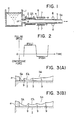
- Fig. 1 is a tundish for containing molten steel 11 from a ladle (not shown); 1 is a horizontal mold having a cooling water passage 2A in the wall thereof.
- the horizontal mold 2 is horizontally fitted, through a feed nozzle 3 and a break ring 4, to an opening 1A formed in the lower portion of the side wall of the tundish 1, and is cooled by cooling water supplied into the cooling water passage 2A.
- 1, 5 is a cast steel strand having a square cross-sectional shape, which has been horizontally and intermittently withdrawn by a plurality of pinch rolls described later from the horizontal mold 2;
- 5A is a solidified shell of the cast steel strand 5;
- 6 is a cooling zone provided following the horizontal mold 2 on the same horizontal level as that of the horizontal mold 2;
- 7 are a plurality of spray nozzles provided in the cooling zone 6, the plurality of spray nozzles 7 spraying cooling water from above and below the cast steel strand 5 onto the surface of the solidified shell 5A of the cast steel strand 5 passing through the cooling zone 6 to cool the cast steel strand 5;
- 8 are a plurality of pinch rolls for horizontally and intermittently withdrawing the cast steel strand 5 from the horizontal mold 2 by a plurality of cycles each comprising a pull and a push.
- the cast steel strand 5 is manufactured as follows using the above-mentioned conventional horizontal type continuous casting machine. Molten steel 11 contained in the tundish 1 flows through the feed nozzle 3 and the break ring 4 into the horizontal mold 2 and is cooled therein. The cast steel strand 5 thus cast is horizontally and intermittently withdrawn from the horizontal mold 2 by the pinch rolls 8. Then, the cast steel strand 5 is cooled by cooling water ejected from the plurality of spray nozzles 7 provided in the cooling zone 6 onto the surface of the solidified shell 5A of the cast steel strand 5 passing through the cooling zone 6. Then, the cast steel strand 5 is completely solidified to the core by natural cooling. The cast steel strand 5 is thus continuously manufactured.
- FIG. 2 An example of the above-mentioned cycle comprising a pull and a push which is applied to the cast steel strand 5 is illustrated in Fig. 2.
- the abscissa shows time, and the ordinate indicates the pulling speed of the cast steel strand 5 in the upper half starting from the point 0, and the compressive force applied to the cast steel strand 5 by a push of the cast steel strand 5 in the lower half starting from the above-mentioned point 0.
- Figs. 3(A) and 3(B) illustrate partial sectional views of the formation of the solidified shell 5A of the cast steel strand 5 in the horizontal mold 2 when horizontally and intermittently withdrawing the cast steel strand 5 in consecution from the horizontal mold 2.
- Fig. 3(A) is a partial sectional view illustrating the formation of a solidified shell 5'A ofthe cast steel strand (5) during the pull in one cycle comprising a pull and a push of the cast steel strand 5
- Fig. 3(B) is another partial sectional view illustrating the formation of the solidified shell 5'A of the cast steel strand 5 upon the completion of the above-mentioned one cycle.
- the cast steel strand 5 is horizontally pulled from the horizontal mold 2 at a prescribed pulling speed for a prescribed pulling time. Then, the cast steel strand 5 is pushed back in the direction opposite to the pulling direction for a prescribed pushing time. This pushing back prevents the solidified shell 5A of the cast steel strand 5 from being broken due to heat contraction in the horizontal mold 2 and a breakout from occurring as a result.
- an incompletely welded portion known as a cold shut 9 is formed on the juncture face between two adjacent portions 5'A and 5"A of the solidified shell 5A of the cast steel strand 5, which adjacent portions 5'A and 5"A are formed by a plurality of cycles each comprising a pull and a push.
- the cause of the formation of the above-mentioned cold shut 9 is as follows. As shown in Figs. 3(A) and 3(B), the solidified shell 5'A of the cast steel strand 5 formed during one cycle comprising a pull and a push is cooled from three sides including not only the side facing the horizontal mold 2 but also the side facing the break ring 4 and the side facing the solidified shell 5"A of the cast steel strand 5 which has already been formed in the cycle precedent to that one cycle. As a result, solidification of the solidified shell 5'A of the cast steel strand 5 begins on the three sides mentioned above.
- the structure of the solidified shell 5'A which contacts with the soldified shell 5"A of the cast steel strand 5 grows horizontally and in the direction opposite to that of the structure of the solidified shell 5"A of the cast steel strand 5.
- the structure of the juncture face between the solidified shells 5'A and 5"A of the cast steel strand 5 becomes discontinuous so that a complete welding is not achieved at this juncture face. This causes occurrence of a cold shut 9.
- the above-mentioned cold shut 9 poses no problem if it is completely welded, but when not welded completely, cracks are produced along the cold shut 9 at the time of thermal contraction of the solidified shell 5A of the cast steel strand 5 caused by cooling in the cooling zone 6. These cracks become fine cold shut cracks. When the cast steel strand 5 having these fine cold shut cracks is rolled, these fine cold shut cracks remain on the surface portion of the resultant rolled product, thus remarkably deteriorating the ' quality of the rolled product.
- the cold shut 9 can be welded by increasing the pushing force of the cast steel strand 5 to some extent. However, if an excessive pushing force is applied to the cast steel strand 5, buckling occurs in the solidified shell 5A of the cast steel strand 5, resulting in a breakout of unsolidified molten steel.
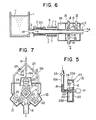
- Fig. 4 10 is a ladle; 1 is a tundish containing molten steel 11 from the ladle 10; 12 is a teeming nozzle fixed vertically to an opening 1A of the bottom wall of the tundish 1; 2' is a vertical mold provided directly below the tundish 1; 5 is a cast steel strand vertically downwardly withdrawn continuously from the vertical mold 2' by a plurality of pinch rolls 8; 5A is a solidified shell of the cast steel strand 5; 6 is a cooling zone provided following the vertical mold 2' on the same vertical level as that of the vertical mold 2', a plurality of spray nozzles (not shown) for ejecting cooling water onto the solidified shell 5A of the cast steel strand 5 withdrawn from the vertical mold 2' being provided in the cooling zone 6; 13 is a shooting zone provided following the cooling zone 6 on the same vertical level as that of the cooling zone 6; and 14 are a plurality of shooters provided in the shooting zone 13, each of the plurality of shooters 14
- the plurality of metal shots 15 discharged from the shooting zone 13 after ejection onto the surface of the solidified shell 5A of the cast steel strand 5 are supplied in recycle into a plurality of shooters 14 in the shooting zone 13 by a metal shot recycling means.
- the above-mentioned metal shot recycling means comprises: a metal shot discharge pipe 16 for transporting the plurality of metal shots 15 discharged from the shooting zone 13 after ejection onto the surface of the solidified shell 5A of the cast steel strand 5 to a conveyor described later, the metals hot discharge pipe 16 being downwardly inclined toward the downstream end thereof; a conveyor 17 for transporting the plurality of metal shots 15 discharged through the metals hot discharge pipe 16 to a hopper described later, the conveyor 17 being provided substantially vertically at the downstream end of the metal shot discharge pipe 16; a hopper 18 for storing the plurality of metal shots 15 received from the conveyor 17 and supplying same to the plurality of shooters 14 in the shooting zone 13, the hopper 18 being provided above the shooting zone 13; and a metal shot supply pipe 19 for communicating the hopper 18 with the shooting zone 13, the metal shot supply pipe 19 supplying the plurality of metal shots 15 through respective branch pipes 19A into the plurality of shooters 14 in the shooting zone 13.
- Fig. 5 20 is a vertical disk; 21 is a motor for rotating the vertical disk 20 at a high speed; 22 are a plurality of impellers radially and vertically fixed to one surface of the vertical disk 20; 23 is a cover for covering the vertical disk 20 and the plurality of impellers 22; 24 is a shooting port formed at a portion of a peripheral wall 23A of the cover 23; and 25 is a valve fitted to each of the respective branch pipes 19A of the metal shot supply pipe 19 for regulating the flow rate of the plurality of metal shots 15.
- the branch pipe 19A of the metal shot supply pipe 19 communicates with the central portion of one of vertical sides walls 23B of the cover 23.
- the plurality of metal shots 15, made of steel or cast iron, have a diameter of from about .5 mm to about 3.5 mm.
- Fine cold shut cracks which have been produced on the surface portion of the solidified shell 5A of the cast steel strand 5 withdrawn from the vertical mold 2', are welded and removed under the pressure applied by the plurality of metal shots 15 thus ejected.
- the plurality of metal shots 15 discharged from the shooting zone 13 after ejection onto the surface of the solidified shell 5A of the cast steel strand 5 in the shooting zone 13 are transported through the metal shot discharge pipe 16 to the conveyor 17, and then transported on the conveyor 17 to the hopper 18 for use in recycle.
- the above-mentioned prior art involves the following problems.
- the shooting zone 13 is provided immediately following the cooling zone 6, the plurality of metal shots 15 are ejected once the surface of the solidified shell 5A of the cast steel strand 5 immediately after cooling in the cooling zone 6.
- ejection of the plurality of metal shots 15 onto the surface of the solidified shell 5A of the cast steel strand 5 which has been hardened by cooling in the cooling zone 6 does not permit substantially complete welding and removal of the cold shut cracks which have been produced in the surface portion of the solidified shell 5A of the cast steel strand 5, under the pressure applied by the plurality of metal shots 15.
- An object of the present invention is therefore to provide, when manufacturing a cast steel strand by a horizontal type continuous casting machine, a method and an apparatus which permit substantially complete welding and removal of fine cold shut cracks produced on the surface portion of a solidified shell of a horizontally and continuously cast steel strand, under the pressure applied by a plurality of metal shots ejected onto the surface of said solidified shell.
- Another object of the present invention is to provide, when manufacturing a cast steel strand by a horizontal type continuous casting machine, a method and an apparatus which facilitate welding and removal of fine cold shut cracks produced on the surface portion of a solidified shell of a horizontally and continuously cast steel strand, under the pressure applied by a plurality of metal shots ejected onto the surface of said solidified shell, by keeping said cast steel strand in a non-oxidizing atmosphere to prevent oxidation of said fine cold shut cracks.
- a further another object of the present invention is, when manufacturing a cast steel strand by a horizontal type continuous casting machine, to provide a method and an apparatus which permit drying without using any additional fuel a plurality of metal shots which are wet by cooling water and which are ejected onto the surface of a solidified shell of a horizontally and continuously caststeel strand for the purpose of welding and removal of fine cold shut cracks produced on the surface portion of said solidified shell.
- a method for removing fine cold shut cracks on a horizontally and continuously cast steel strand using ejection of a plurality of metal shot which comprises:
- the present invention was made on the basis of the above-mentioned finding.
- the method and the apparatus for removing fine cold shut cracks produced on the surface portion of a solidified shell of a horizontally and continuously cast steel strand of the present invention is described below with reference to the drawings.
- Fig. 6 is a schematic descriptive view illustrating an embodiment of the apparatus of the present invention as installed on the conventional horizontal type continuous casting machine
- Fig. 7 is a sectional view of Fig. 6 cut along the line A-A.
- 1 is a tundish for containing molten steel 11 from a ladle (not shown);
- 2 is a horizontal mold having a cooling water passage 2A in the wall thereof.
- the horizontal mold 2 is horizontally fitted, through a feed nozzle 3 and a break ring 4, to an opening 1A formed at the lower portion of the side wall of the tundish 1, and is cooled by cooling water supplied into the cooling water passage 2A.
- Figs. 6 is a schematic descriptive view illustrating an embodiment of the apparatus of the present invention as installed on the conventional horizontal type continuous casting machine
- Fig. 7 is a sectional view of Fig. 6 cut along the line A-A.
- 1 is a tundish for containing molten steel 11 from a ladle (not shown);
- 2
- 5 is a cast steel strand having a square cross-sectional shape, which has been horizontally and intermittently withdrawn by a plurality of pinch rolls (not shown) from the horizontal mold 2;
- 5A is a solidified shell of the cast steel strand 5;
- 6 is a cooling zone provided following the horizontal mold 2 on the same horizontal level as that of the horizontal mold 2;
- 7 are a plurality of spray nozzles provided in the cooling zone 6, the plurality of spray nozzles 7 spraying cooling water from above and below the cast steel strand 5 onto the surface of the solidified shell 5A of the cast steel strand 5 passing through the cooling zone 6 to cool the cast steel strand;
- 26 is a heat-restoring zone provided following the cooling zone 6 on the same horizontal level as that of the cooling zone 6, the heat-restoring zone 26 re-increasing the temperature of the surface portion of the solidified shell 5A of the cast steel strand 5 passing through the heat-restoring zone 26 with the use of heat of molten steel in the interior of the cast steel strand 5
- the plurality of shooters 14 are installed two each above and below the cast steel strand 5.
- the two upper shooters 14 are installed at a prescribed interval in the longitudinal direction of the cast steel strand 5.
- the two lower shooters 14 are installed at a prescribed interval in the width direction of the cast steel strand 5.
- Each of the two upper shooters 14 ejects the plurality of metal shot 15 onto respective one of the two upper surfaces of the cast steel strand 5.
- Each of the two lower shooters 14 ejects the plurality of metal shot 15 onto each of the two lower surfaces of the cast steel strand 5.
- Fine cold shut cracks on the surface portion of the solidified shell 5A of the cast steel strand 5 are welded and removed as follows by means of the above-mentioned apparatus of the present invention.
- the cast steel strand 5 is horizontally and intermittently withdrawn from the horizontal mold 2 by a plurality of cycles each comprising a pull and a push. Then, the cast steel strand 5 is cooled by cooling water sprayed from the plurality of spray nozzles 7 provided in the cooling zone 6 onto the surface of the solidified shell 5A of the cast steel strand 5 passing through the cooling zone 6 to accelerate growth of the thickness of the solidified shell 5A.
- the temperature of the surface portion of the solidified shell 5A of the cast steel strand 5 passing through the heat-restoring zone 26 is re-increased under the effect of heat of molten steel in the interior of the cast steel strand 5. This softens the surface portion of the solidified shell 5A of the cast steel strand 5.
- the plurality of metal shot 15 are continuously ejected in the shooting zone 13 from the plurality of shooters 14 onto the thus softened surface of the solidified shell 5A of the cast steel strand 5 passing through the shooting zone 13.
- the plurality of metal shot 15 discharged from the shooting zone 13 after ejection onto the surface of the solidified shell 5A of the cast steel strand 5 passing through the shooting zone 13, are recycled by means of a metal shot recycling means using for example a pneumatic carrier gas into the plurality of shooters 14 in the shooting zone 13.
- a metal shot recycling means using for example a pneumatic carrier gas into the plurality of shooters 14 in the shooting zone 13.
- An embodiment of the metal shot recycling means - using the pneumatic carrier gas will be described later.
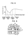
- Fig. 8 is a graph illustrating the transition of the surface temperature of the solidified shell 5A of the cast steel strand 5 having a square cross-section with a side length of 115 mm when horizontally and intermittently withdrawing the cast steel strand 5 from the horizontal mold 2 by the plurality of cycles each comprising a pull and a push, with the use of the apparatus of the present invention as shown in Fig. 6.
- the surface temperature of the solidified shell 5A of the cast steel strand 5 decreases to about 950°C immediately after passing through the secondary cooling zone, i.e., the cooling zone 6, but increases to about 1,250°C immediately after passing through the heat-restoring zone 26.
- the primary cooling zone means the horizontal mold 2 which is cooled by cooling water circulating in the wall thereof
- the secondary cooling zone means the cooling zone 6 provided following the horizontal mold 2.
- Fig. 9 is a schematic descriptive view illustrating another embodiment of the apparatus of the present invention having an inert gas supply means for supplying an inert gas into the cooling zone 6, the heat-restoring zone 26 and the shooting zone 13.
- the cooling zone 6, the heat-restoring zone 26 and the shooting zone 13 are covered by a cover 27, and the cooling zone 6,the heat-restoring zone 26 and the shooting zone 13 are kept in a non-oxidizing atmosphere by an inert gas such as nitrogen gas or argon gas supplied from an inert gas supply means into said zones 6, 26 and 13.
- an inert gas such as nitrogen gas or argon gas supplied from an inert gas supply means into said zones 6, 26 and 13.
- the inert gas supply means comprises an inert gas supply pipe 28 which communicates with the cooling zone 6, the heat-restoring zone 26 and the shooting zone 13 through respective branch pipes 28A each having a valve 30 for regulating the gas flow rate.
- the amount of oxygen remaining in the cooling zone 6, the heat-restoring zone 26 and the shooting zone 13 is constantly measured by an oxygen concentration meter 29.
- the flow rate of the inert gas supplied into said zones 6, 26 and 13 is regulated by the valve 30 provided in each of the branch pipes 28A of the inert gas supply pipe 28 so that the amount of oxygen may not exceed a prescribed value.
- the apparatus in the embodiment shown in Fig. 9 has the same construction as that of the apparatus of the present invention shown in Figs. 6 and 7 except for the inert gas supply means for supplying the inert gas into the cooling zone 6, the heat-restoring zone 26 and the shooting zone 13, further description is not made here.
- the fine cold shut cracks produced on the surface portion of the solidified shell 5A of the cast steel strand 5 are not oxidized during the period from the beginning of horizontal withdrawal of the cast steel strand 5 from the horizontal mold (not shown) up to the ejection of the plurality of metal shot 15.
- the fine cold shut cracks are thus more easily and more certainly welded and removed than in the case where said zone 6, 26 and 13 are not kept in a non-oxidizing atmosphere.
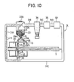
- Fig. 10 is a schematic descriptive view illustrating further another embodiment of the present invention having a metal shot recycling means using a pneumatic carrier gas.
- the plurality of metal shot 15 discharged from the shooting zone 13 after ejection onto the surface of the solidified shell 5A of the cast steel strand 5 are recycled by a metal shot recycling means using a pneumatic carrier gas into the plurality of shooters 14 in the shooting zone 13.
- the metal shot recycling means comprises: a looped pneumatic carrier pipe 31, the pneumatic carrier pipe 31 recycling the plurality of metal shots 15 discharged from the shooting zone 13 through a metal shot discharge pipe 16 after ejection onto the surface of the solidified shell 5A of the cast steel strand 5 into the plurality of shooters 14 in the shooting zone 13; a blower 32 for blowing the pneumatic carrier gas into the pneumatic carrier pipe 31, the blower 32 being provided in the middle of the pneumatic carrier pipe 31; a hopper 33 for storing the plurality of metal shot 15 sent through the pneumatic carrier pipe 31 and supplying same into the plurality of shooters 14 in the shooting zone 13, the hopper 33 being provided in the middle of the pneumatic carrier pipe 31 in the upstream of the blower 32; a dust collector 34 for removing dust produced from the cast steel strand 5 and the plurality of metal shot 15, the duct collector 34 being provided in the middle of the pneumatic carrier pipe 31 between the blower 32 and the hopper 33; and a dehumidifier 35 for a looped pneumatic
- the hopper 33 has a baffle plate 33A for deflecting the plurality of metal shot 15 sent through the pneumatic carrier pipe 31 to the upper portion of the interior of the hopper 33 to drop onto the bottom thereof.
- the hopper 33 has at the upper portion thereof a metal shot supply port 33B, which can be freely opened and closed for replenishing new metal shots.
- the plurality of metal shot 15 discharged from the shooting zone 13 through the metal shot discharge port 16 are recycled into the plurality of shooters 14 in the shooting zone 13 as follows by means of the above-mentioned metal shot recycling means.
- the plurality of metal shot 15 discharged from the shooting zone 13 through the metal shot discharge pipe 16 into the pneumatic carrier pipe 31A after ejection onto the surface of the solidified shell 5A of the cast steel strand 5 in the shooting zone 13, are sent by the pneumatic carrier gas through the pneumatic carrier pipe 31A to the hopper 33, where the plurality of metal shot 15 are deflected by the baffle plate 33A in the hopper 33, and drop onto the bottom of the hopper 33.
- the plurality of metal shots 15 thus stored in the hopper 33 are recycled through the metal shot supply pipe 19 and the respective branch pipes 19A to the plurality of shooters 14 in the shooting zone 13.
- the pneumatic carrier gas after carrying the plurality of metal shot 15 to the hopper 33 not only contains dust produced from the cast steel strand 5 and the plurality of metal shot 15, but also is humidified by cooling water penetrating from the cooling zone (not shown) through the heat-restoring zone 26 into the shooting zone 13.
- the pneumatic carrier gas containing dust and humidity as mentioned above flows from the hopper 33 through the pneumatic carrier 31 B into the dust collector 34, and then through the pneumatic carrier pipe 31 C into the dehumidifier 35.
- the dust and the humidity are thus removed from the pneumatic carrier gas after transporting the plurality of metal shot 15.
- the pneumatic carrier gas after removal of dust and humidity returns through the pneumatic carrier pipe 31 D to the blower 32 and then flows from the blower 32 through the pneumatic carrier pipe 31 E again into the pneumatic carrier pipe 31A.
- the plurality of metal shot 15 discharged from the shooting zone 13 are smoothly recycled to the plurality of shooters 14 in the shooting zone 13.
- Fig. 11 is a schematic descriptive view illustrating further another embodiment of the present invention having a heat exchanger 36 for heating the pneumatic carrier gas.
- the pneumatic carrier gas passing through the pneumatic carrier pipe 31A is heated through heat exchange with the cast steel strand 5 passing through the heat exchanger 36 provided in the middle of the pneumatic carrier pipe 31 in the downstream of the blower 32 and in the upstream of the shooting zone 13.
- the plurality of metal shot 15 which are wet by cooling water penetrating from the cooling zone (not shown) through the heat-restoring zone 26 into the shooting zone 13 are dried by the pneumatic carrier gas thus heated during transportation through the pneumatic carrier pipe 31A.
- Fig. 12 is a partially cutaway side view of the heat exchanger 36.
- the heat exchanger 36 comprises: an inner cylinder 37 through which the cast steel strand 5 passes; a plurality of fins 38 for improving the efficiency of heat exchange, the plurality of fins 38 being fixed to the outer surface of the inner cylinder 37 along the axial line thereof and at intervals in the circumferential direction thereof; an outer cylinder 39 concentrically surrounding the inner cylinder 37 with a space therebetween; a pair of annular walls 40 each having an opening of the same diameter as that of the inner cylinder 37, the pair of annular walls 40 being fixed respectively to the both ends of the inner cylinder 37 and the outer cylinder 39; and a heating chamber 41 comprising the space defined by the inner cylinder 37, the outer cylinder 39 and the pair of annular walls 40.
- the plurality of metal shot 15 which are wet by cooling water pentrating from the cooling zone 6 through the heat-restoring zone 26 into the shooting zone 13 are dried as follows by the apparatus shown in Figs. 11 and 12.
- the pneumatic carrier gas sent from the blower 32 through the pneumatic carrier pipe 31E enters the heating chamber 41 of the heat exchanger 36, where the pneumatic carrier gas is heated through heat exchange with the high-temperature cast steel strand 5 passing through the inner cylinder 37 of the heat exchanger 36.
- the pneumatic carrier gas thus heated is sent to the pneumatic carrier gas 31A.
- the plurality of metal shot 15 which are wet by the cooling water pentrating from the cooling zone (not shown) through the heat-restoring zone 26 into the shooting zone 13 are dried by the thus heated pneumatic carrier gas during transportation through the pneumatic carrier pipe 31A.
- the following effects are available. If the plurality of metal shot 15 which are wet by the cooling water are oxidized and adhere to each other to form large lumps, and these lumps clog up the metal shot supply pipe 19, this would make it impossible to eject the plurality of metal shot 15. According to the embodiment mentioned above, however, the plurality of metal shot 15 are dried by the heated pneumatic carrier gas, thus causing no such problem. Further, drying of the plurality of metal shots 15 does not require any additional fuel at all.
- an inert gas of the same kind as the inert gas supplied to these zones 6, 26 and 13 should be employed as the pneumatic carrier gas.
- the apparatus of the present invention shown in Fig. 6 was installed in the manner as shown in Fig. 6 on the conventional horizontal type continuous casting machine, and a cast steel strand 5 having a square cross-section with a side length of 115 mm of-a a structural steel was horizontally and intermittently withdrawn from the horizontal mold 2 at a withdrawal speed of 2.0 m/min. Then, the cast steel strand 5 was passed consecutively through the cooling zone 6, the heat-restoring zone 26 and the shooting zone 13.
- the solidified shell 5A of the cast steel strand 5 immediately after passing through the cooling zone 6 had a surface temperature of about 950°C, and immediately after passing through the heat-restoring zone 26, the solidified shell 5A of the cast steel strand 5 has a surface temperature of about 1,275°C.
- metal shots 15 made of steel having a diameter of about 1.4 mm were continuously ejected at a speed of about 70 m/sec from each of the shooters 14 onto the surface of the solidified shell 5A of the cast steel strand 5.
Landscapes
- Engineering & Computer Science (AREA)
- Mechanical Engineering (AREA)
- Chemical & Material Sciences (AREA)
- Crystallography & Structural Chemistry (AREA)
- Materials Engineering (AREA)
- Metallurgy (AREA)
- Organic Chemistry (AREA)
- Continuous Casting (AREA)
Claims (12)
Applications Claiming Priority (4)
| Application Number | Priority Date | Filing Date | Title |
|---|---|---|---|
| JP17888482A JPS5970447A (ja) | 1982-10-12 | 1982-10-12 | 連続鋳造鋳片の表面疵除去方法 |
| JP178884/82 | 1982-10-12 | ||
| JP13418983A JPS6027453A (ja) | 1983-07-22 | 1983-07-22 | 水平連続鋳片の表面欠陥の発生防止方法および装置 |
| JP134189/83 | 1983-07-22 |
Publications (2)
| Publication Number | Publication Date |
|---|---|
| EP0108490A1 EP0108490A1 (de) | 1984-05-16 |
| EP0108490B1 true EP0108490B1 (de) | 1987-01-14 |
Family
ID=26468358
Family Applications (1)
| Application Number | Title | Priority Date | Filing Date |
|---|---|---|---|
| EP83305864A Expired EP0108490B1 (de) | 1982-10-12 | 1983-09-28 | Verfahren und Vorrichtung zum Entfernen durch Abstrahlen mit Hilfe eines Metallgriesses eines nach der horizontalen Stranggussmethode hergestellten Stranges |
Country Status (5)
| Country | Link |
|---|---|
| US (1) | US4532980A (de) |
| EP (1) | EP0108490B1 (de) |
| KR (1) | KR870001939B1 (de) |
| BR (1) | BR8305609A (de) |
| DE (1) | DE3369082D1 (de) |
Families Citing this family (9)
| Publication number | Priority date | Publication date | Assignee | Title |
|---|---|---|---|---|
| US4709572A (en) * | 1984-07-31 | 1987-12-01 | Sumitomo Metal Industries, Ltd. | Method of processing continuously cast slabs |
| JPS61235043A (ja) * | 1985-04-10 | 1986-10-20 | Hitachi Zosen Corp | 薄板連続鋳造装置 |
| KR940003251B1 (ko) * | 1989-03-30 | 1994-04-16 | 신닛뽄 세이데쓰 가부시끼가이샤 | 급냉응고 박주판을 출발소재로 하는 압연성 금속판의 제조방법 |
| US5286315A (en) * | 1989-03-30 | 1994-02-15 | Nippon Steel Corporation | Process for preparing rollable metal sheet from quenched solidified thin cast sheet as starting material |
| US5533248A (en) * | 1992-05-12 | 1996-07-09 | Tippins Incorporated | Method of steel processing using an inline grinder |
| US5590703A (en) * | 1995-04-17 | 1997-01-07 | Eckert; C. Edward | Aluminum surface treatment |
| DE19814299A1 (de) * | 1998-03-31 | 1999-10-07 | Volkswagen Ag | Verfahren zum Bearbeiten eines Werkstücks aus Metall |
| DE102017207942A1 (de) * | 2017-05-11 | 2018-11-15 | Sms Group Gmbh | Stranggießanlage und Verfahren zur Herstellung eines metallischen Produkts |
| CN111922914A (zh) * | 2020-08-24 | 2020-11-13 | 广州九岳天装饰工程有限公司 | 一种数控水切割机床用水箱 |
Family Cites Families (7)
| Publication number | Priority date | Publication date | Assignee | Title |
|---|---|---|---|---|
| FR404194A (fr) * | 1909-06-18 | 1909-11-24 | Gustave Gin | Laminage direct des fers et aciers et dispositif pour le réaliser |
| US2565959A (en) * | 1949-10-04 | 1951-08-28 | Charles B Francis | Method of casting metal continuously |
| GB1093785A (en) * | 1965-08-27 | 1967-12-06 | Tilghman Wheelabrator Ltd | Improvements in or relating to apparatus for the treatment of castings |
| AT298712B (de) * | 1970-01-09 | 1972-05-25 | Voest Ag | Stranggießanlage zum kontinuierlichen Gießen von schmelzflüssigen Metallen |
| GB1323360A (en) * | 1970-11-14 | 1973-07-11 | Schaumburg G | Process and apparatus for the detectability of surface defects in continuously cast products |
| JPS58360A (ja) * | 1981-04-20 | 1983-01-05 | ヘイズレツト・ストリツプ・キヤステイング・コ−ポレ−シヨン | 陽極製造用二重ベルト鋳造機より退去した後の新しく鋳造された銅製品の酸化を防止する方法および装置 |
| JPS58128255A (ja) * | 1982-01-25 | 1983-07-30 | Nippon Kokan Kk <Nkk> | 鋼の連続鋳造法 |
-
1983
- 1983-09-28 EP EP83305864A patent/EP0108490B1/de not_active Expired
- 1983-09-28 DE DE8383305864T patent/DE3369082D1/de not_active Expired
- 1983-10-11 US US06/540,835 patent/US4532980A/en not_active Expired - Fee Related
- 1983-10-11 BR BR8305609A patent/BR8305609A/pt unknown
- 1983-10-12 KR KR1019830004830A patent/KR870001939B1/ko not_active Expired
Also Published As
| Publication number | Publication date |
|---|---|
| DE3369082D1 (en) | 1987-02-19 |
| EP0108490A1 (de) | 1984-05-16 |
| US4532980A (en) | 1985-08-06 |
| KR870001939B1 (ko) | 1987-10-23 |
| BR8305609A (pt) | 1984-05-15 |
| KR840006300A (ko) | 1984-11-29 |
Similar Documents
| Publication | Publication Date | Title |
|---|---|---|
| EP0108490B1 (de) | Verfahren und Vorrichtung zum Entfernen durch Abstrahlen mit Hilfe eines Metallgriesses eines nach der horizontalen Stranggussmethode hergestellten Stranges | |
| US4424855A (en) | Method for cooling continuous casting | |
| US3670400A (en) | Process and apparatus for fabricating a hot worked metal layer from atomized metal particles | |
| US4658882A (en) | Machine for direct rolling of steel casting and producing steel product therefrom | |
| US3416222A (en) | Manufacture of elongate articles | |
| JP3742656B2 (ja) | ストリップ鋳造のための非接触の吸熱部 | |
| US3587718A (en) | Continuous casting apparatus | |
| US6315030B1 (en) | High speed continuous casting device and relative method | |
| CN110860664B (zh) | 立式空心圆坯连铸机及出坯方法 | |
| JPH06344089A (ja) | ウェブを連続的に冷却する装置と方法 | |
| US4705466A (en) | Method and apparatus for producing rolled product from metal droplets | |
| KR20020063886A (ko) | 박형 강 스트립 제조 방법 및 장치 | |
| JPH0255642A (ja) | ストリツプ鋼を連続的に鋳造する方法および装置 | |
| JPS561251A (en) | Continuous casting method | |
| CA1233618A (en) | Method and apparatus for direct casting of crystalline strip in non-oxidizing atmosphere | |
| US3818972A (en) | Cast bar draft angle | |
| JPS59229268A (ja) | 連続鋳造鋳片のデスケ−リング方法 | |
| JP3377340B2 (ja) | 連続鋳造方法 | |
| JPS609553A (ja) | 絞り込み式連続鋳造機 | |
| JP3978855B2 (ja) | 連鋳鋳片の最適熱延前加熱方法 | |
| JP2955044B2 (ja) | 環状鋼製品の連続鋳造方法および連続鋳造装置 | |
| JP2006181583A (ja) | 連続鋳造鋳片の製造方法 | |
| AU731277B2 (en) | Strip casting | |
| JPS597464A (ja) | 薄鋼板の連続鋳造法およびその装置 | |
| JPS5868459A (ja) | 連続鋳造方法 |
Legal Events
| Date | Code | Title | Description |
|---|---|---|---|
| PUAI | Public reference made under article 153(3) epc to a published international application that has entered the european phase |
Free format text: ORIGINAL CODE: 0009012 |
|
| AK | Designated contracting states |
Designated state(s): BE DE FR GB SE |
|
| 17P | Request for examination filed |
Effective date: 19840717 |
|
| GRAA | (expected) grant |
Free format text: ORIGINAL CODE: 0009210 |
|
| AK | Designated contracting states |
Kind code of ref document: B1 Designated state(s): BE DE FR GB SE |
|
| REF | Corresponds to: |
Ref document number: 3369082 Country of ref document: DE Date of ref document: 19870219 |
|
| ET | Fr: translation filed | ||
| PLBE | No opposition filed within time limit |
Free format text: ORIGINAL CODE: 0009261 |
|
| STAA | Information on the status of an ep patent application or granted ep patent |
Free format text: STATUS: NO OPPOSITION FILED WITHIN TIME LIMIT |
|
| 26N | No opposition filed | ||
| PG25 | Lapsed in a contracting state [announced via postgrant information from national office to epo] |
Ref country code: GB Effective date: 19890928 |
|
| PG25 | Lapsed in a contracting state [announced via postgrant information from national office to epo] |
Ref country code: SE Effective date: 19890929 |
|
| PG25 | Lapsed in a contracting state [announced via postgrant information from national office to epo] |
Ref country code: BE Effective date: 19890930 |
|
| BERE | Be: lapsed |
Owner name: NIPPON KOKAN K.K. Effective date: 19890930 |
|
| GBPC | Gb: european patent ceased through non-payment of renewal fee | ||
| PG25 | Lapsed in a contracting state [announced via postgrant information from national office to epo] |
Ref country code: FR Effective date: 19900531 |
|
| PG25 | Lapsed in a contracting state [announced via postgrant information from national office to epo] |
Ref country code: DE Effective date: 19900601 |
|
| REG | Reference to a national code |
Ref country code: FR Ref legal event code: ST |
|
| EUG | Se: european patent has lapsed |
Ref document number: 83305864.7 Effective date: 19900521 |