EP0108473B1 - Einrichtung zum Bestimmen der Hublängendauer - Google Patents
Einrichtung zum Bestimmen der Hublängendauer Download PDFInfo
- Publication number
- EP0108473B1 EP0108473B1 EP83304908A EP83304908A EP0108473B1 EP 0108473 B1 EP0108473 B1 EP 0108473B1 EP 83304908 A EP83304908 A EP 83304908A EP 83304908 A EP83304908 A EP 83304908A EP 0108473 B1 EP0108473 B1 EP 0108473B1
- Authority
- EP
- European Patent Office
- Prior art keywords
- display
- slew
- memory
- representative
- signals
- Prior art date
- Legal status (The legal status is an assumption and is not a legal conclusion. Google has not performed a legal analysis and makes no representation as to the accuracy of the status listed.)
- Expired
Links
- 230000015654 memory Effects 0.000 claims description 35
- 230000004044 response Effects 0.000 description 2
- 230000001934 delay Effects 0.000 description 1
- 230000003111 delayed effect Effects 0.000 description 1
- 238000010586 diagram Methods 0.000 description 1
- 230000006870 function Effects 0.000 description 1
- 230000007274 generation of a signal involved in cell-cell signaling Effects 0.000 description 1
- 238000000034 method Methods 0.000 description 1
- 230000000644 propagated effect Effects 0.000 description 1
Images
Classifications
-
- G—PHYSICS
- G09—EDUCATION; CRYPTOGRAPHY; DISPLAY; ADVERTISING; SEALS
- G09G—ARRANGEMENTS OR CIRCUITS FOR CONTROL OF INDICATING DEVICES USING STATIC MEANS TO PRESENT VARIABLE INFORMATION
- G09G1/00—Control arrangements or circuits, of interest only in connection with cathode-ray tube indicators; General aspects or details, e.g. selection emphasis on particular characters, dashed line or dotted line generation; Preprocessing of data
- G09G1/06—Control arrangements or circuits, of interest only in connection with cathode-ray tube indicators; General aspects or details, e.g. selection emphasis on particular characters, dashed line or dotted line generation; Preprocessing of data using single beam tubes, e.g. three-dimensional or perspective representation, rotation or translation of display pattern, hidden lines, shadows
- G09G1/08—Control arrangements or circuits, of interest only in connection with cathode-ray tube indicators; General aspects or details, e.g. selection emphasis on particular characters, dashed line or dotted line generation; Preprocessing of data using single beam tubes, e.g. three-dimensional or perspective representation, rotation or translation of display pattern, hidden lines, shadows the beam directly tracing characters, the information to be displayed controlling the deflection and the intensity as a function of time in two spatial co-ordinates, e.g. according to a cartesian co-ordinate system
Definitions
- the invention pertains to display systems and more particularly to the determination of the time interval between the start and end of a segment on the display.
- the generator Before start and end position signals for a symbol are coupled from a symbol generator to a display unit, the generator must receive a signal indicating that the prior symbol has been completed.
- circuitry coupled to the deflection amplifiers, which detect when the beam of the CRT has stopped, generate a signal at the conclusion of a symbol segment. This signal is coupled to the logic circuitry of the symbol generator which waits until the signal is received before proceeding with the next symbol segment.
- end signals must be received from all of the display units before the next symbol commands are issued. Logic must therefore be included in the symbol generator to prevent the delay of subsequent signal generation for an inordinate length of time due to a delayed or missing signal from a faulty display unit.
- digital data representative of the beam position on the display face is coupled from a vector symbol generator to address a length memory.
- the display is divided into regions by segmenting the axes. Slew time between regions for all combinations of start and end positions in an axis are represented by a code for each combination which is entered into a corresponding cell of the length memories.
- These codes, one for each axis, when addressed by the data from the symbol generator, are coupled to address an elapsed time memory, wherein each location contains a code representative of the time required to slew the beam between the start and end positions represented by the addressing code.
- the code at the addressed position of the elapsed time memory may then be applied to a counter, wherefrom a signal is coupled to the symbol generator at the conclusion of a count determined by the code coupled from the elapsed time memory to indicate the conclusion of the slew.
- the symbol generator is allowed to proceed with the next symbol segment.
- the present invention may be used with a calligraphic display which receives symbol display information from a digital vector generator.
- a digital vector generator can command a change in the position of the CRT beam simply by clocking a new digital value into the proper register.
- This digital value is converted to an analogue signal, amplified, and used to drive the CRT deflection means.
- the analogue portions of the circuit require a significant amount of time to respond to the instantaneous change in the digital value. This response time varies as a function of the start and finish positions of the slew.
- These delays can vary over an order of magnitude, depending upon the start and end positions of the slew. 8 microseconds to 100 microseconds being a typical range.
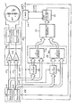
- digital signals representative of the desired beam position are coupled from the symbol (vector) generator 10 wherein the coordinates of each start and end position are entered into the X register 11 and Y register 12.
- the digital signals in registers 11 and 12 are coupled via busses 13 and 14 to a digital-to analogue converter 15 wherefrom analogue signals are coupled via deflection amplifiers 16 to the CRT 17.
- Digital signals for an n-bit code, which may comprise the four most significant bits of the position signals coupled to the busses 13 and 14, are coupled from the X register 11 and Y register 12 to a slew length timer 20 via busses 21 and 22, respectively.
- These four-bit digital signals divide, the X and Y axes of the CRT display into 16 segments, each uniquely represented by one of the possible 16 4-bit codes on the bus assigned to the axis on which the segment lies.
- the display is divided into 256 regions, each uniquely represented by an 8-bit signal, 4 bits for the X segment and 4 bits for Y segment.
- the utilisation of the 4 significant bits provide appreciable savings in memory sizes throughout the system while maintaining useful symbol length and position information.
- a signal Prior to commanding a new beam position, a signal is coupled from the symbol generator 10 via a line 23 to a timer 24. In response to this signal, the timer 24 clocks registers 26 and 27 via a line 25, thereby storing the 4-bit X coordinate of the start position in register 26 and the 4-bit Y coordinate of the start position in register 27.
- the X and Y coordinates of the start position are latched in the registers 26 and 27 and coupled therefrom to X length memory 31 and Y length memory 32 of a length memory 30.
- digital signals representative of the coordinates of the final position of the slew are entered into the X register 11 and the Y register 12 of the vector generator 10. The 4 most significant bits of each of these signals are respectively coupled, via the busses 21 and 22, to the X length memory 31 and the Y length memory 32.
- the length memory 31 and the length memory 32 are each addressed 8-bit words, 4 bits for the starting and 4 bits for the end position.
- each memory location corresponds to a slew from an initial region, one of the 16 regions along an axis, to an end region on the same axis.
- information concerning the direction and approximate magnitude of slew is preserved in 8 bits.
- the 256 possible combinations of the start and end positions along an axis, representing the one axis slew time are arranged in order and divided into 32 groups of 8, each group represented by an m-bit code, such that m ⁇ 2n. In one embodiment m may equal 5 to establish a 5-bit word unique for the group. This group code is inserted at the memory position of each member of the group.
- the two five-bit codes which are addressed in the X length memory 31 and the Y length memory 32 are coupled to a comparator memory 33 wherein a cell is uniquely assigned to each X length-Y length pair.
- Each X length and Y length corresponds to a deflection time interval on the CRT display. These time intervals are compared for each X length-Y length pair and the greater of the two is selected to representative thereof.
- the code required by a variable delay 34 is the code required by a variable delay 34 to produce the time interval selected for that X length Y length pair.
- the selected time intervals are arranged in order and divided into groups of four, each group being assigned a unique p-bit code, which may be an 8-bit code, satisfying the inequality p ⁇ 2m.
- p may be equal to, or greater than, 2m, p being determined by the input code to the variable delay 34.
- variable delay 34 Upon receipt of a timing signal from the timer 24, the variable delay 34 loads the binary code addressed in the comparator memory 33 by the X length memory 31 and Y length memory 32. This timing signal occurs after the initial position is latched into the X start register 26 and Y start register 27, after the X register 11 and Y register 12 of the vector generator 10 have received the end beam position, and after the resulting binary signals are propagated through the memory to the input terminals of the variable delay 34.
- the variable delay 34 which may be a parallel loaded binary counter well known in the art, provides a signal to the vector generator 10 after a time delay determined by the code coupled to its input terminals. This pulse signals the end of the slew to the vector generator 10 which then proceeds with the next symbol segment.
Landscapes
- Engineering & Computer Science (AREA)
- Radar, Positioning & Navigation (AREA)
- Remote Sensing (AREA)
- Physics & Mathematics (AREA)
- Computer Hardware Design (AREA)
- General Physics & Mathematics (AREA)
- Theoretical Computer Science (AREA)
- Controls And Circuits For Display Device (AREA)
Claims (9)
dadurch gekennzeichnet, daß es eine Einrichtung (20) zum Empfangen von Signalen vom Symbolgenerator enthält, welche die Start- und Endposition für die erste und die zweite Anzeigeachse auf dem Bildschirm (17) bezeichnen und Signale liefert, die den Schwenkzeitintervallen zwischen den Start- und den Endpositionen für die erste und die zweite Anzeigeachse entsprechen;
Applications Claiming Priority (2)
| Application Number | Priority Date | Filing Date | Title |
|---|---|---|---|
| US06/416,397 US4532504A (en) | 1982-09-09 | 1982-09-09 | Slew length timer |
| US416397 | 1995-04-06 |
Publications (3)
| Publication Number | Publication Date |
|---|---|
| EP0108473A2 EP0108473A2 (de) | 1984-05-16 |
| EP0108473A3 EP0108473A3 (en) | 1987-07-01 |
| EP0108473B1 true EP0108473B1 (de) | 1990-09-12 |
Family
ID=23649812
Family Applications (1)
| Application Number | Title | Priority Date | Filing Date |
|---|---|---|---|
| EP83304908A Expired EP0108473B1 (de) | 1982-09-09 | 1983-08-25 | Einrichtung zum Bestimmen der Hublängendauer |
Country Status (4)
| Country | Link |
|---|---|
| US (1) | US4532504A (de) |
| EP (1) | EP0108473B1 (de) |
| JP (1) | JPS5950494A (de) |
| DE (1) | DE3381878D1 (de) |
Families Citing this family (3)
| Publication number | Priority date | Publication date | Assignee | Title |
|---|---|---|---|---|
| US4841473A (en) * | 1986-12-19 | 1989-06-20 | Robert S. Salzman | Computer architecture providing programmable degrees of an almost condition |
| US5066945A (en) * | 1987-10-26 | 1991-11-19 | Canon Kabushiki Kaisha | Driving apparatus for an electrode matrix suitable for a liquid crystal panel |
| US20060061518A1 (en) * | 2004-09-23 | 2006-03-23 | Honeywell International Inc. | Angular and positional dependent vector display |
Family Cites Families (8)
| Publication number | Priority date | Publication date | Assignee | Title |
|---|---|---|---|---|
| US3539860A (en) * | 1969-04-01 | 1970-11-10 | Adage Inc | Vector generator |
| DE1936051C3 (de) * | 1969-07-16 | 1974-04-18 | Dr.-Ing. Rudolf Hell Gmbh, 2300 Kiel | Verfahren zur Aufzeichnung von Strichzeichnungen auf dem Bildschirm eines Elektronenstrahlrohres und Schaltungsanordnung zur Durchführung des Verfahrens |
| US3638214A (en) * | 1970-01-23 | 1972-01-25 | Rca Corp | Vector generator |
| FR2134821A5 (de) * | 1971-04-21 | 1972-12-08 | Cit Alcatel | |
| US3800183A (en) * | 1972-06-08 | 1974-03-26 | Digital Equipment Corp | Display device with means for drawing vectors |
| US3952297A (en) * | 1974-08-01 | 1976-04-20 | Raytheon Company | Constant writing rate digital stroke character generator having minimal data storage requirements |
| US4093996A (en) * | 1976-04-23 | 1978-06-06 | International Business Machines Corporation | Cursor for an on-the-fly digital television display having an intermediate buffer and a refresh buffer |
| GB2080078A (en) * | 1980-06-13 | 1982-01-27 | Elliott Brothers London Ltd | Display Systems |
-
1982
- 1982-09-09 US US06/416,397 patent/US4532504A/en not_active Expired - Lifetime
-
1983
- 1983-07-08 JP JP58124551A patent/JPS5950494A/ja active Granted
- 1983-08-25 EP EP83304908A patent/EP0108473B1/de not_active Expired
- 1983-08-25 DE DE8383304908T patent/DE3381878D1/de not_active Expired - Fee Related
Also Published As
| Publication number | Publication date |
|---|---|
| US4532504A (en) | 1985-07-30 |
| JPH0527866B2 (de) | 1993-04-22 |
| JPS5950494A (ja) | 1984-03-23 |
| EP0108473A3 (en) | 1987-07-01 |
| EP0108473A2 (de) | 1984-05-16 |
| DE3381878D1 (de) | 1990-10-18 |
Similar Documents
| Publication | Publication Date | Title |
|---|---|---|
| US3226694A (en) | Interrupt system | |
| US3470542A (en) | Modular system design | |
| US4483001A (en) | Online realignment of memory faults | |
| US5130991A (en) | Method and apparatus for crc computation | |
| US3553651A (en) | Memory storage system | |
| JPH04293144A (ja) | コンピュータシステム | |
| EP0186382A1 (de) | Programmierbare digitale Hystereseschaltung | |
| US4593373A (en) | Method and apparatus for producing n-bit outputs from an m-bit microcomputer | |
| US4142233A (en) | Refreshing system for dynamic memory | |
| US4803654A (en) | Circular first-in, first out buffer system for generating input and output addresses for read/write memory independently | |
| EP0006480B1 (de) | Verfahren und Vorrichtung zur Erzeugung von Bytes zur Fehlerortung und Paritätsprüfung | |
| US4639894A (en) | Data transferring method | |
| CA1233280A (en) | System for displaying alphanumeric messages | |
| EP0108473B1 (de) | Einrichtung zum Bestimmen der Hublängendauer | |
| US4128872A (en) | High speed data shifter array | |
| US3238510A (en) | Memory organization for data processors | |
| EP0367995B1 (de) | Vektordatenübertragungssteuerung | |
| EP0057096A2 (de) | Informationsverarbeitungsanlage | |
| US4479180A (en) | Digital memory system utilizing fast and slow address dependent access cycles | |
| US3794970A (en) | Storage access apparatus | |
| US5021990A (en) | Output pulse generating apparatus | |
| US3993980A (en) | System for hard wiring information into integrated circuit elements | |
| US3335411A (en) | Stock information storage and request system | |
| US5553260A (en) | Apparatus for expanding compressed binary data | |
| EP0843253B1 (de) | Verfahren zur Reduzierung der Anzahl der Bits von Konstanten in einer Datenverarbeitungsvorrichtung |
Legal Events
| Date | Code | Title | Description |
|---|---|---|---|
| PUAI | Public reference made under article 153(3) epc to a published international application that has entered the european phase |
Free format text: ORIGINAL CODE: 0009012 |
|
| AK | Designated contracting states |
Designated state(s): DE FR GB IT |
|
| PUAL | Search report despatched |
Free format text: ORIGINAL CODE: 0009013 |
|
| AK | Designated contracting states |
Kind code of ref document: A3 Designated state(s): DE FR GB IT |
|
| 17P | Request for examination filed |
Effective date: 19870806 |
|
| RAP1 | Party data changed (applicant data changed or rights of an application transferred) |
Owner name: HONEYWELL INC. |
|
| 17Q | First examination report despatched |
Effective date: 19890509 |
|
| ITF | It: translation for a ep patent filed | ||
| GRAA | (expected) grant |
Free format text: ORIGINAL CODE: 0009210 |
|
| AK | Designated contracting states |
Kind code of ref document: B1 Designated state(s): DE FR GB IT |
|
| REF | Corresponds to: |
Ref document number: 3381878 Country of ref document: DE Date of ref document: 19901018 |
|
| ET | Fr: translation filed | ||
| PLBE | No opposition filed within time limit |
Free format text: ORIGINAL CODE: 0009261 |
|
| STAA | Information on the status of an ep patent application or granted ep patent |
Free format text: STATUS: NO OPPOSITION FILED WITHIN TIME LIMIT |
|
| 26N | No opposition filed | ||
| ITTA | It: last paid annual fee | ||
| PGFP | Annual fee paid to national office [announced via postgrant information from national office to epo] |
Ref country code: FR Payment date: 19940614 Year of fee payment: 12 |
|
| PGFP | Annual fee paid to national office [announced via postgrant information from national office to epo] |
Ref country code: GB Payment date: 19940617 Year of fee payment: 12 |
|
| PGFP | Annual fee paid to national office [announced via postgrant information from national office to epo] |
Ref country code: DE Payment date: 19940902 Year of fee payment: 12 |
|
| PG25 | Lapsed in a contracting state [announced via postgrant information from national office to epo] |
Ref country code: GB Effective date: 19950825 |
|
| GBPC | Gb: european patent ceased through non-payment of renewal fee |
Effective date: 19950825 |
|
| PG25 | Lapsed in a contracting state [announced via postgrant information from national office to epo] |
Ref country code: FR Effective date: 19960430 |
|
| PG25 | Lapsed in a contracting state [announced via postgrant information from national office to epo] |
Ref country code: DE Effective date: 19960501 |
|
| REG | Reference to a national code |
Ref country code: FR Ref legal event code: ST |