EP0108362A1 - Apparatus for plant cultivation - Google Patents
Apparatus for plant cultivation Download PDFInfo
- Publication number
- EP0108362A1 EP0108362A1 EP83110828A EP83110828A EP0108362A1 EP 0108362 A1 EP0108362 A1 EP 0108362A1 EP 83110828 A EP83110828 A EP 83110828A EP 83110828 A EP83110828 A EP 83110828A EP 0108362 A1 EP0108362 A1 EP 0108362A1
- Authority
- EP
- European Patent Office
- Prior art keywords
- plant
- light
- chamber
- base member
- lighting means
- Prior art date
- Legal status (The legal status is an assumption and is not a legal conclusion. Google has not performed a legal analysis and makes no representation as to the accuracy of the status listed.)
- Granted
Links
- 239000013307 optical fiber Substances 0.000 claims abstract description 22
- 230000029553 photosynthesis Effects 0.000 claims description 8
- 238000010672 photosynthesis Methods 0.000 claims description 8
- 239000007788 liquid Substances 0.000 claims description 3
- MWUXSHHQAYIFBG-UHFFFAOYSA-N Nitric oxide Chemical compound O=[N] MWUXSHHQAYIFBG-UHFFFAOYSA-N 0.000 claims 3
- 238000012216 screening Methods 0.000 claims 1
- QVGXLLKOCUKJST-UHFFFAOYSA-N atomic oxygen Chemical compound [O] QVGXLLKOCUKJST-UHFFFAOYSA-N 0.000 abstract description 4
- 229910052760 oxygen Inorganic materials 0.000 abstract description 4
- 239000001301 oxygen Substances 0.000 abstract description 4
- 229910002092 carbon dioxide Inorganic materials 0.000 description 9
- CURLTUGMZLYLDI-UHFFFAOYSA-N Carbon dioxide Chemical compound O=C=O CURLTUGMZLYLDI-UHFFFAOYSA-N 0.000 description 7
- 239000000835 fiber Substances 0.000 description 7
- 239000000463 material Substances 0.000 description 6
- 238000010276 construction Methods 0.000 description 5
- 241000282414 Homo sapiens Species 0.000 description 4
- 235000013399 edible fruits Nutrition 0.000 description 4
- 230000001902 propagating effect Effects 0.000 description 4
- 239000001569 carbon dioxide Substances 0.000 description 3
- 238000006243 chemical reaction Methods 0.000 description 3
- 230000000243 photosynthetic effect Effects 0.000 description 3
- 238000000034 method Methods 0.000 description 2
- 238000012544 monitoring process Methods 0.000 description 2
- 229910052724 xenon Inorganic materials 0.000 description 2
- FHNFHKCVQCLJFQ-UHFFFAOYSA-N xenon atom Chemical compound [Xe] FHNFHKCVQCLJFQ-UHFFFAOYSA-N 0.000 description 2
- 230000001143 conditioned effect Effects 0.000 description 1
- 230000003750 conditioning effect Effects 0.000 description 1
- 230000008878 coupling Effects 0.000 description 1
- 238000010168 coupling process Methods 0.000 description 1
- 238000005859 coupling reaction Methods 0.000 description 1
- 239000001963 growth medium Substances 0.000 description 1
- 238000012986 modification Methods 0.000 description 1
- 230000004048 modification Effects 0.000 description 1
- 230000003287 optical effect Effects 0.000 description 1
- 230000000717 retained effect Effects 0.000 description 1
- 239000002699 waste material Substances 0.000 description 1
- XLYOFNOQVPJJNP-UHFFFAOYSA-N water Substances O XLYOFNOQVPJJNP-UHFFFAOYSA-N 0.000 description 1
Images

Classifications
-
- A—HUMAN NECESSITIES
- A01—AGRICULTURE; FORESTRY; ANIMAL HUSBANDRY; HUNTING; TRAPPING; FISHING
- A01G—HORTICULTURE; CULTIVATION OF VEGETABLES, FLOWERS, RICE, FRUIT, VINES, HOPS OR SEAWEED; FORESTRY; WATERING
- A01G7/00—Botany in general
- A01G7/04—Electric or magnetic or acoustic treatment of plants for promoting growth
- A01G7/045—Electric or magnetic or acoustic treatment of plants for promoting growth with electric lighting
-
- A—HUMAN NECESSITIES
- A01—AGRICULTURE; FORESTRY; ANIMAL HUSBANDRY; HUNTING; TRAPPING; FISHING
- A01G—HORTICULTURE; CULTIVATION OF VEGETABLES, FLOWERS, RICE, FRUIT, VINES, HOPS OR SEAWEED; FORESTRY; WATERING
- A01G31/00—Soilless cultivation, e.g. hydroponics
- A01G31/02—Special apparatus therefor
-
- A—HUMAN NECESSITIES
- A01—AGRICULTURE; FORESTRY; ANIMAL HUSBANDRY; HUNTING; TRAPPING; FISHING
- A01G—HORTICULTURE; CULTIVATION OF VEGETABLES, FLOWERS, RICE, FRUIT, VINES, HOPS OR SEAWEED; FORESTRY; WATERING
- A01G9/00—Cultivation in receptacles, forcing-frames or greenhouses; Edging for beds, lawn or the like
- A01G9/24—Devices or systems for heating, ventilating, regulating temperature, illuminating, or watering, in greenhouses, forcing-frames, or the like
- A01G9/249—Lighting means
-
- Y—GENERAL TAGGING OF NEW TECHNOLOGICAL DEVELOPMENTS; GENERAL TAGGING OF CROSS-SECTIONAL TECHNOLOGIES SPANNING OVER SEVERAL SECTIONS OF THE IPC; TECHNICAL SUBJECTS COVERED BY FORMER USPC CROSS-REFERENCE ART COLLECTIONS [XRACs] AND DIGESTS
- Y02—TECHNOLOGIES OR APPLICATIONS FOR MITIGATION OR ADAPTATION AGAINST CLIMATE CHANGE
- Y02P—CLIMATE CHANGE MITIGATION TECHNOLOGIES IN THE PRODUCTION OR PROCESSING OF GOODS
- Y02P60/00—Technologies relating to agriculture, livestock or agroalimentary industries
- Y02P60/14—Measures for saving energy, e.g. in green houses
-
- Y—GENERAL TAGGING OF NEW TECHNOLOGICAL DEVELOPMENTS; GENERAL TAGGING OF CROSS-SECTIONAL TECHNOLOGIES SPANNING OVER SEVERAL SECTIONS OF THE IPC; TECHNICAL SUBJECTS COVERED BY FORMER USPC CROSS-REFERENCE ART COLLECTIONS [XRACs] AND DIGESTS
- Y02—TECHNOLOGIES OR APPLICATIONS FOR MITIGATION OR ADAPTATION AGAINST CLIMATE CHANGE
- Y02P—CLIMATE CHANGE MITIGATION TECHNOLOGIES IN THE PRODUCTION OR PROCESSING OF GOODS
- Y02P60/00—Technologies relating to agriculture, livestock or agroalimentary industries
- Y02P60/20—Reduction of greenhouse gas [GHG] emissions in agriculture, e.g. CO2
- Y02P60/21—Dinitrogen oxide [N2O], e.g. using aquaponics, hydroponics or efficiency measures
Definitions
- the present invention relates to an apparatus for cultivating plants under well nourished and lighted conditions.
- the primary requisite for the cultivation of plants is adequately conditioning various factors related thereto such as light, nourishment, carbon dioxide (C0 2 ) and heat as well as ambient conditions including temperature and humidity.
- C0 2 carbon dioxide
- the effort to satisfy all these factors has brought about a problem in view of the atmosphere which is desirable for human beings. For example, excessive supply of C0 2 is harmful for human beings and excessive humidity or heat, undesirable.
- An apparatus for cultivating a plant of the present invention comprises a base member for supporting a plant which has sealed dark chamber defined therein.
- the dark chamber accommodates a root portion of the plant.
- a support assembly supports a stem and leaf portion of the plant which protrudes upwardly from the base member.
- Lighting means is provided for supplying light for photosynthesis to the stem and leaf portion of the plant.
- an apparatus for plant cultivation includes a sealed dark chamber and a sealed lighted chamber which accommodates a root portion and a stem and leaf portion of a plant respectively.
- the lighted chamber is defined by a transparent housing above the dark chamber and the lighting is provided by optical fibers.
- the dark chamber is supplied with nourishment, oxygen and the like, while the lighted chamber is supplied with C0 2 -containing air which is controlled to a predetermined temperature and humidity. The supply of light occurs on a scheduled basis in accordance with a state of stomata of the plant.
- an apparatus of the present invention includes a hollow base section 10 which is kept dark by a lid from above, although not shown in the drawing.
- a plant P has a root portion thereof accommodated in the dark base section or, as will be referred to as, dark chamber 10. Sufficient amounts of culture medium and water for nourishing the plant P are fed into the dark chamber 10 by a method well known in the art.
- a support member 12 is disposed in the dark chamber 10 as illustrated.
- a plurality of columns 14 stand upright on the support member'12 with their lower ends received in holes 16 which are formed in the support 12.
- the columns 14 are rigidly retained together by beams 18 at some positions along the length thereof.
- This assembly of the columns 14 and beams 18 serves as a support for supporting a stem and leaf portion of the plant P.
- an upper portion of the assembly is fixedly held and closed by an opaque lid member 20, for example.
- each of the columns 14 comprises a transparent tube in which an elongate transparent member 22 having a triangular cross-section is disposed.
- Optical fibers 24 are also disposed in the transparent tube and respectively fixed in contact with the three sides of the triangular elongate member 22, so that light propagating through fiber optic cables 26 may enter the optical fibers 24 associated with the fiber optic cables 26.
- an apparatus for focusing sunlight or artificial light is located at those ends of the fiber optic cables 26 which are remote from the optical fibers 24. Light focused by the focusing apparatus is selectively or simultaneously introduced into the fiber optic cables 26 and therethrough into the optical fibers 24, thus being radiated from the optical fibers 24 to irradiate the plant P.
- Photoradiators have been proposed in various forms such as one comprising an optical fiber on which a light diffusing material is locally deposited in order to allow light propagating through the optical fiber to be radiated through the light diffusing material.
- the principle of such a photoradiator is applicable to the optical fibers 24 shown and described.
- laying the optical fibers 24 on and along the respective sides of the triangular, transparent column 22 is advantageous over the above-mentioned structure because the light introduced from the optical fibers 24 into the triangular member 22 advances toward vertical angles while being reflected by adjacent two sides of the triangle and, in the meantime, the incidence angle to the two sides progressively increases to allow the light to be radiated with ease from the triangular member 22.
- the optical fibers 24 on the triangle promotes effective supply of the light propagating therethrough to the plant P.
- a transparent cover member or housing 28 defines a sealed lighted chamber 30 in which the plant P is confined.
- carbon dioxide may be suitably fed into the chamber 30 by a method well known to the art.
- the housing 28 may comprise two housing halves 28a and 28b which are identical in shape and fastened to each other as by bolts 34 to form the sealed chamber 30.
- the supply of light to the plant P for photosynthesis is needed when the stomata are open and not when they are closed. For more efficient photosynthesis, therefore, it is desirable to interrupt the irradiation and, at the same time, to screen the whole chamber 30 from externally derived light rays while the stomata are closed.
- this is implemented by a curtain 36 which hangs at the transparent housing 28. While the stomata of the plant P are closed, the curtain 36 may be lowered to intercept the external light tending to enter the chamber 30. At the same time, the supply of light into the optical fibers 24 may be switched off to leave the plant P in complete darkness within the chamber 30. In this condition, the plant P shifts the product of photosynthesis toward fruits hanging thereon. Stated another way, cultivation of the plant P will proceed more effectively if the curtain 36 is lowered only when the product of photosynthesis is being shifted to the fruits.
- While the supply of light to the apparatus may be switched on and off by monitoring the state of the stomata of the plant, a plurality of such apparatuses may be prepared to supply them with light alternately in order to attain more effective use of light.
- the light switching operation may be scheduled by estimating the period because the light supply control effected by actually monitoring the stomata would result in an intricate and expensive construction.
- FIG. 5 another embodiment of the present invention is shown and generally comprises a hollow base 50 and a transparent cover or housing 52.
- the base 50 defines a dark chamber 54 and the housing 52, a sealed lighted chamber 56.
- the plant P has a root portion accommodated in the dark chamber 54 and a stem and leaf portion in the lighted chamber 56.
- An apertured tube assembly 58 is disposed in the dark chamber 54 in order to supply the root portion of the plant P with nourishment, oxygen and the like necessary for the growth thereof.
- Culture liquid, air and the like are circulated from a source (not shown) to the apertured tube assembly 58 and therethrough into the dark chamber 54 via an inlet tube 60.
- the waste liquid served the function in the dark chamber 54 is discharged from an outlet tube 62 to return to the source. Meanwhile, the air supplied oxygen to the root of the plant P is discharged through an exhaust tube 64.
- a number of light sources 68 Disposed in the sealed chamber 56 are a number of light sources 68 which are necessary for causing the plant P to perform photosynthetic reactions.
- CO 2 , hot and humid air and the like are circulated into the lighted chamber 56 via an inlet tube 70 and out therefrom via an outlet tube 72.
- the atmosphere inside the lighted chamber 56 is conditioned to specific properties of the plant P, e.g., to a humidity of 70%, a C0 2 concentration of 3%, and temperature of 25-28°C.
- the light sources 68 in the chamber 56 may be of any desired type so long as it is capable of emitting light of a wavelength which is needed for photosynthetic reactions, e.g., xenon lamps. It is desirable, however, to employ light sources which do not entail heat, in view of the fact that heat is unnecessary for photosynthetic reactions.
- Such light sources may be typified by, as illustrated, optical fibers 74 and a light transmitting material 76 locally deposited on the optical fibers 74 and having a refractive index which is larger than that of the optical fibers 74. In this construction, light propagating through the optical fibers 74 will stream to the outside at each of the locations where the light transmissive material 76 is deposited.
- the optical fibers 74 are bundled up at upper ends thereof to be optically connected to a fiber optic cable 78 by an optical coupling 80.
- the cable 78 faces a lens assembly which functions to focus light emanating from a light source, which may be the sun or an artificial light source such as a xenon lamp.
- a light source which may be the sun or an artificial light source such as a xenon lamp.
- light converged by the lens assembly into the fiber optic cable 78 will propagate therethrough to the optical fibers 74 so as to irradiate the plant P streaming through the light transmissive material 76.
- the sealed chamber 56 is defined by the transparent housing 52 to allow one to see the interior of the chamber. To gather fruit hanging on the plant P, one may enter the chamber 56 after replacing the CO 2-containing, hot and humid air by ordinary clean air. Alternatively, a number of openable windows may be formed in the housing 52 to allow one to gather the fruits by reaching out his or her hands through the windows.
- the present invention provides an apparatus for plant cultivation which effectively raises a plant with a simple and compact construction and without effecting the atmosphere which human beings enjoy.
Abstract
Description
- The present invention relates to an apparatus for cultivating plants under well nourished and lighted conditions.
- The primary requisite for the cultivation of plants is adequately conditioning various factors related thereto such as light, nourishment, carbon dioxide (C02) and heat as well as ambient conditions including temperature and humidity. However, the effort to satisfy all these factors has brought about a problem in view of the atmosphere which is desirable for human beings. For example, excessive supply of C02 is harmful for human beings and excessive humidity or heat, undesirable.
- It is therefore an object of the present invention to provide a plant cultivating apparatus which is capable of effectively raising plants while insuring the atmosphere required for human beings.
- It is another object of the present invention to provide a simple and space-effective apparatus for plant cultivation.
- It is another object of the present invention to provide a generally improved apparatus for plant cultivation.
- An apparatus for cultivating a plant of the present invention comprises a base member for supporting a plant which has sealed dark chamber defined therein. The dark chamber accommodates a root portion of the plant. A support assembly supports a stem and leaf portion of the plant which protrudes upwardly from the base member. Lighting means is provided for supplying light for photosynthesis to the stem and leaf portion of the plant.
- In accordance with the present invention, an apparatus for plant cultivation includes a sealed dark chamber and a sealed lighted chamber which accommodates a root portion and a stem and leaf portion of a plant respectively. The lighted chamber is defined by a transparent housing above the dark chamber and the lighting is provided by optical fibers. The dark chamber is supplied with nourishment, oxygen and the like, while the lighted chamber is supplied with C02-containing air which is controlled to a predetermined temperature and humidity. The supply of light occurs on a scheduled basis in accordance with a state of stomata of the plant.
- The above and other objects, features and advantages of the present invention will become apparent from the following detailed description taken with the accompanying drawings.
-
- Figure 1 is a perspective view of a plant cultivating apparatus embodying the present invention;
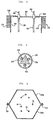
- Figure 2 is a fragmentary section of the apparatus shown in Figure 1;
- Figure 3 is a cross-section of a column included in the apparatus of Figure 1;
- Figure 4 is a cross-section along line IV-IV of Figure 1; and
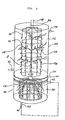
- Figure 5 is a schematic perspective view of another embodiment of the present invention.
- While the apparatus for plant cultivation of the present invention is susceptible of numerous physical embodiments, depending upon the environment and requirements of use, substantial numbers of the herein shown and described embodiments have been made, tested and used, and all have performed in an eminently satisfactory manner.
- Referring to Figure 1 of the drawings, an apparatus of the present invention includes a
hollow base section 10 which is kept dark by a lid from above, although not shown in the drawing. A plant P has a root portion thereof accommodated in the dark base section or, as will be referred to as,dark chamber 10. Sufficient amounts of culture medium and water for nourishing the plant P are fed into thedark chamber 10 by a method well known in the art. - A
support member 12 is disposed in thedark chamber 10 as illustrated. A plurality ofcolumns 14 stand upright on the support member'12 with their lower ends received inholes 16 which are formed in thesupport 12. Thecolumns 14 are rigidly retained together bybeams 18 at some positions along the length thereof. This assembly of thecolumns 14 andbeams 18 serves as a support for supporting a stem and leaf portion of the plant P. As shown in Figure 2, an upper portion of the assembly is fixedly held and closed by anopaque lid member 20, for example. - Referring to Figure 3, each of the
columns 14 comprises a transparent tube in which an elongatetransparent member 22 having a triangular cross-section is disposed.Optical fibers 24 are also disposed in the transparent tube and respectively fixed in contact with the three sides of the triangularelongate member 22, so that light propagating through fiberoptic cables 26 may enter theoptical fibers 24 associated with the fiberoptic cables 26. In detail, an apparatus for focusing sunlight or artificial light is located at those ends of the fiberoptic cables 26 which are remote from theoptical fibers 24. Light focused by the focusing apparatus is selectively or simultaneously introduced into the fiberoptic cables 26 and therethrough into theoptical fibers 24, thus being radiated from theoptical fibers 24 to irradiate the plant P. - Photoradiators have been proposed in various forms such as one comprising an optical fiber on which a light diffusing material is locally deposited in order to allow light propagating through the optical fiber to be radiated through the light diffusing material. The principle of such a photoradiator is applicable to the
optical fibers 24 shown and described. However, laying theoptical fibers 24 on and along the respective sides of the triangular,transparent column 22 is advantageous over the above-mentioned structure because the light introduced from theoptical fibers 24 into thetriangular member 22 advances toward vertical angles while being reflected by adjacent two sides of the triangle and, in the meantime, the incidence angle to the two sides progressively increases to allow the light to be radiated with ease from thetriangular member 22. In short, theoptical fibers 24 on the triangle promotes effective supply of the light propagating therethrough to the plant P. - While the construction described so far suffices for effective cultivation of the plant by the sufficient supply of nourishment and light, photosynthesis will occur more effectively if carbon dioxide (C02) can be fed positively to the plant P. In accordance with the present invention, a transparent cover member or
housing 28 defines a sealedlighted chamber 30 in which the plant P is confined. Alid 32 made of an opaque material, for example, is located on top of thehousing 28 andlid 20 to define the sealedchamber 30 in cooperation with thehousing 28. In this construction, carbon dioxide may be suitably fed into thechamber 30 by a method well known to the art. - As shown in Figure 4, the
housing 28 may comprise two housing halves 28a and 28b which are identical in shape and fastened to each other as bybolts 34 to form the sealedchamber 30. - The supply of light to the plant P for photosynthesis is needed when the stomata are open and not when they are closed. For more efficient photosynthesis, therefore, it is desirable to interrupt the irradiation and, at the same time, to screen the
whole chamber 30 from externally derived light rays while the stomata are closed. In this particular embodiment, this is implemented by acurtain 36 which hangs at thetransparent housing 28. While the stomata of the plant P are closed, thecurtain 36 may be lowered to intercept the external light tending to enter thechamber 30. At the same time, the supply of light into theoptical fibers 24 may be switched off to leave the plant P in complete darkness within thechamber 30. In this condition, the plant P shifts the product of photosynthesis toward fruits hanging thereon. Stated another way, cultivation of the plant P will proceed more effectively if thecurtain 36 is lowered only when the product of photosynthesis is being shifted to the fruits. - While the supply of light to the apparatus may be switched on and off by monitoring the state of the stomata of the plant, a plurality of such apparatuses may be prepared to supply them with light alternately in order to attain more effective use of light. The light switching operation may be scheduled by estimating the period because the light supply control effected by actually monitoring the stomata would result in an intricate and expensive construction.
- Referring to Figure 5, another embodiment of the present invention is shown and generally comprises a
hollow base 50 and a transparent cover orhousing 52. Again, thebase 50 defines adark chamber 54 and thehousing 52, a sealedlighted chamber 56. The plant P has a root portion accommodated in thedark chamber 54 and a stem and leaf portion in thelighted chamber 56. Anapertured tube assembly 58 is disposed in thedark chamber 54 in order to supply the root portion of the plant P with nourishment, oxygen and the like necessary for the growth thereof. Culture liquid, air and the like are circulated from a source (not shown) to the aperturedtube assembly 58 and therethrough into thedark chamber 54 via an inlet tube 60. The waste liquid served the function in thedark chamber 54 is discharged from an outlet tube 62 to return to the source. Meanwhile, the air supplied oxygen to the root of the plant P is discharged through anexhaust tube 64. - Disposed in the sealed
chamber 56 are a number oflight sources 68 which are necessary for causing the plant P to perform photosynthetic reactions. CO2, hot and humid air and the like are circulated into thelighted chamber 56 via an inlet tube 70 and out therefrom via an outlet tube 72. The atmosphere inside thelighted chamber 56 is conditioned to specific properties of the plant P, e.g., to a humidity of 70%, a C02 concentration of 3%, and temperature of 25-28°C. - The
light sources 68 in thechamber 56 may be of any desired type so long as it is capable of emitting light of a wavelength which is needed for photosynthetic reactions, e.g., xenon lamps. It is desirable, however, to employ light sources which do not entail heat, in view of the fact that heat is unnecessary for photosynthetic reactions. Such light sources may be typified by, as illustrated,optical fibers 74 and a light transmitting material 76 locally deposited on theoptical fibers 74 and having a refractive index which is larger than that of theoptical fibers 74. In this construction, light propagating through theoptical fibers 74 will stream to the outside at each of the locations where the light transmissive material 76 is deposited. - The
optical fibers 74 are bundled up at upper ends thereof to be optically connected to afiber optic cable 78 by anoptical coupling 80. At the end remote from thefibers 74, thecable 78 faces a lens assembly which functions to focus light emanating from a light source, which may be the sun or an artificial light source such as a xenon lamp. In operation, light converged by the lens assembly into thefiber optic cable 78 will propagate therethrough to theoptical fibers 74 so as to irradiate the plant P streaming through the light transmissive material 76. - As previously described, the sealed
chamber 56 is defined by thetransparent housing 52 to allow one to see the interior of the chamber. To gather fruit hanging on the plant P, one may enter thechamber 56 after replacing the CO 2-containing, hot and humid air by ordinary clean air. Alternatively, a number of openable windows may be formed in thehousing 52 to allow one to gather the fruits by reaching out his or her hands through the windows. - It will be apparent that the principle discussed in conjuction with the stomata of the plant P in the first embodiment is applicable to the second embodiment as well.
- In summary, it will be seen that the present invention provides an apparatus for plant cultivation which effectively raises a plant with a simple and compact construction and without effecting the atmosphere which human beings enjoy.
- Various modifications will become possible for those skilled in the art after receiving the teaching of the present disclosure without departing from the scope thereof.
Claims (13)
Applications Claiming Priority (2)
| Application Number | Priority Date | Filing Date | Title |
|---|---|---|---|
| JP57191239A JPS5982019A (en) | 1982-10-30 | 1982-10-30 | Light culturing tank |
| JP191239/82 | 1982-10-30 |
Related Child Applications (2)
| Application Number | Title | Priority Date | Filing Date |
|---|---|---|---|
| EP86115086A Division EP0241585A3 (en) | 1982-10-30 | 1983-10-28 | Apparatus for plant cultivation |
| EP86115086.0 Division-Into | 1983-10-28 |
Publications (2)
| Publication Number | Publication Date |
|---|---|
| EP0108362A1 true EP0108362A1 (en) | 1984-05-16 |
| EP0108362B1 EP0108362B1 (en) | 1989-01-11 |
Family
ID=16271210
Family Applications (2)
| Application Number | Title | Priority Date | Filing Date |
|---|---|---|---|
| EP86115086A Withdrawn EP0241585A3 (en) | 1982-10-30 | 1983-10-28 | Apparatus for plant cultivation |
| EP83110828A Expired EP0108362B1 (en) | 1982-10-30 | 1983-10-28 | Apparatus for plant cultivation |
Family Applications Before (1)
| Application Number | Title | Priority Date | Filing Date |
|---|---|---|---|
| EP86115086A Withdrawn EP0241585A3 (en) | 1982-10-30 | 1983-10-28 | Apparatus for plant cultivation |
Country Status (7)
| Country | Link |
|---|---|
| US (1) | US4662106A (en) |
| EP (2) | EP0241585A3 (en) |
| JP (1) | JPS5982019A (en) |
| KR (1) | KR880000533B1 (en) |
| AU (1) | AU550446B2 (en) |
| CA (1) | CA1224043A (en) |
| DE (1) | DE3378883D1 (en) |
Cited By (8)
| Publication number | Priority date | Publication date | Assignee | Title |
|---|---|---|---|---|
| EP0130585A2 (en) * | 1983-07-01 | 1985-01-09 | Kei Mori | Light diffusing device |
| EP0130586A2 (en) * | 1983-07-01 | 1985-01-09 | Kei Mori | Apparatus for plant culture |
| GB2192469A (en) * | 1986-07-10 | 1988-01-13 | Kei Mori | A light ray radiating device |
| US4780989A (en) * | 1986-04-30 | 1988-11-01 | Mears Structures, Inc. | Hydroponic assembly |
| GB2205723A (en) * | 1987-06-17 | 1988-12-21 | Norman David Weiss | Growing plants |
| US4969288A (en) * | 1985-03-19 | 1990-11-13 | Kei Mori | Nurturing device for living organisms |
| US20140041291A1 (en) * | 2012-08-13 | 2014-02-13 | Fiskars Brands Finland Oy Ab | Growth container |
| WO2016164652A1 (en) * | 2015-04-09 | 2016-10-13 | Growx Inc. | Systems, methods, and devices for light emitting diode array and horticulture apparatus |
Families Citing this family (25)
| Publication number | Priority date | Publication date | Assignee | Title |
|---|---|---|---|---|
| US4817332A (en) * | 1983-10-28 | 1989-04-04 | Mitsubishi Denki Kabushiki Kaisha | Method of enhancing plant growth and apparatus for performing the same |
| US5174793A (en) * | 1983-10-28 | 1992-12-29 | Mitsubishi Denki K.K. | Method of enhancing plant growth using light levels lower than photo saturation intensity |
| JPS60160821A (en) * | 1984-01-27 | 1985-08-22 | 森 敬 | Plant culture apparatus |
| US4857464A (en) * | 1986-02-21 | 1989-08-15 | Bio-Rational Technologies, Inc. | Mist cultivation of cells |
| US4850135A (en) * | 1988-02-26 | 1989-07-25 | Demarco Jeffery J | Apparatus for stimulating plant growth under controlled conditions |
| US4841670A (en) * | 1988-05-12 | 1989-06-27 | Bitter Paul L | Apparatus for supporting plants |
| JPH071952Y2 (en) * | 1991-03-25 | 1995-01-25 | 株式会社学習研究社 | Germination seedling pot for teaching materials |
| CA2488791A1 (en) * | 2002-06-17 | 2003-12-24 | Hill-Rom Services, Inc. | Apparatus for pulling patient up in bed |
| CN100451647C (en) * | 2006-02-23 | 2009-01-14 | 上海交通大学 | Canopy leaf chamber for determining plant canopy population photosynthesis |
| US20110088317A1 (en) * | 2009-10-16 | 2011-04-21 | Jeffrey Goldberg | Retractable Reflective Wall |
| WO2012002022A1 (en) * | 2010-06-30 | 2012-01-05 | シャープ株式会社 | Light-emitting device and cultivation method |
| JP5920878B2 (en) * | 2011-03-08 | 2016-05-18 | 学校法人明治大学 | Plant cultivation method and plant cultivation apparatus |
| US8776432B2 (en) * | 2012-07-24 | 2014-07-15 | Charles R. NELL, JR. | Integrated trellis machine |
| WO2014097138A1 (en) * | 2012-12-21 | 2014-06-26 | Koninklijke Philips N.V. | A horticulture lighting interface for interfacing at least one lighting system |
| US20200315114A1 (en) * | 2013-10-04 | 2020-10-08 | Charles E. Ankner | Preventing treating and eliminating infection and infestation of plantae in sensu lato by pathogens and pests |
| MX362575B (en) * | 2013-12-31 | 2019-01-25 | Opti Harvest Inc | Harvesting, transmission, spectral modification and delivery of sunlight to shaded areas of plants. |
| FI125733B (en) * | 2014-06-02 | 2016-01-29 | 3Gren Oy | VERTICAL PLANTING PLANT FOR CULTIVATING PLANTS |
| US9807949B2 (en) * | 2014-08-15 | 2017-11-07 | John W. Hamlin | Root environment control system and method |
| EP3193582A4 (en) * | 2014-09-17 | 2018-05-16 | Sulejmani Holdings LLC | Method for increasing the yield of a flowering plant |
| CA2908823A1 (en) * | 2015-09-09 | 2017-03-09 | Zale Lewis David Tabakman | Method and unit for growing vegetables within a closed environment |
| JP2018007620A (en) * | 2016-07-14 | 2018-01-18 | 株式会社小糸製作所 | Plant raising apparatus |
| JP7155243B2 (en) * | 2017-04-10 | 2022-10-18 | ロベル,ケヴィン | Methods and Materials for Extending Plant Survival in Non-Refrigerated Storage Environments |
| US10980190B2 (en) * | 2017-07-18 | 2021-04-20 | Sat Parkash Gupta | Environment-controlled greenhouse with compressor and blower modules |
| US10681877B1 (en) * | 2017-08-02 | 2020-06-16 | Robert Goodwin | Plant growing system |
| US20210007308A1 (en) * | 2018-03-15 | 2021-01-14 | King Abdullah University Of Science And Technology | Energy-efficient closed plant system and method |
Citations (8)
| Publication number | Priority date | Publication date | Assignee | Title |
|---|---|---|---|---|
| GB1143403A (en) * | 1965-02-04 | 1969-02-19 | Nat Res Dev | Apparatus for supplying carbon dioxide to growing plants |
| US3433940A (en) * | 1967-06-07 | 1969-03-18 | Stewart Warner Corp | Fiber optics instrument lighting |
| DE1808001A1 (en) * | 1967-11-17 | 1969-07-10 | Molenaar Johannes | Process for improving plant growth in greenhouses, warm houses and the like. |
| FR2071064A5 (en) * | 1969-12-17 | 1971-09-17 | Barthelemy Jean | Woven fabric - with plastic tape warp, used for plant protection |
| AT331552B (en) * | 1975-01-20 | 1976-08-25 | Ruthner Othmar | METHOD AND DEVICE FOR SUPPLYING LIGHT IN HYDROPONIC PLANT CROPS |
| US4045911A (en) * | 1975-10-01 | 1977-09-06 | Ware R Louis | Versatile horticultural growth apparatus |
| US4166341A (en) * | 1974-08-13 | 1979-09-04 | Bent Vestergaard | Method and apparatus for cultivation of plants grown singly in separate beds |
| EP0031985A1 (en) * | 1980-01-02 | 1981-07-15 | John Russell Prewer | Apparatus and process for the cultivation of plants |
Family Cites Families (13)
| Publication number | Priority date | Publication date | Assignee | Title |
|---|---|---|---|---|
| US1419152A (en) * | 1921-03-29 | 1922-06-13 | Henry L Lansing | Electric flower lamp |
| US3165863A (en) * | 1963-08-22 | 1965-01-19 | Duran Jacqueline | Telescopic plant stake |
| US3348922A (en) * | 1964-07-13 | 1967-10-24 | Whirlpool Co | Carbon dioxide generator |
| US3481073A (en) * | 1967-06-20 | 1969-12-02 | Sunnyside Nurseries Inc | Daylight control means in greenhouses |
| US3532874A (en) * | 1969-02-24 | 1970-10-06 | Poly Optics | Decorative structure |
| US3807088A (en) * | 1971-03-29 | 1974-04-30 | Hydroculture | Controlled environment hydroponic system |
| US3810327A (en) * | 1972-12-29 | 1974-05-14 | J Giansante | Atmosphere control system for growing mushrooms and the like |
| US3930335A (en) * | 1973-04-02 | 1976-01-06 | Controlled Environment Systems, Inc. | Plant growth system |
| US4057933A (en) * | 1976-05-05 | 1977-11-15 | Enyeart Lyle F | Apparatus for aerating comminuted matter such as soil |
| JPS5597350U (en) * | 1978-12-27 | 1980-07-07 | ||
| JPS56154932A (en) * | 1980-04-28 | 1981-11-30 | Mitsui Shipbuilding Eng | Plant cultivation using optical fiber |
| US4369598A (en) * | 1981-03-19 | 1983-01-25 | Beckwith Thomas F | Container element combination for seed sprouting or plant culture |
| US4510555A (en) * | 1984-02-27 | 1985-04-09 | Kei Mori | Ornamental lighting device |
-
1982
- 1982-10-30 JP JP57191239A patent/JPS5982019A/en active Granted
-
1983
- 1983-10-21 KR KR1019830004980A patent/KR880000533B1/en not_active IP Right Cessation
- 1983-10-27 US US06/546,016 patent/US4662106A/en not_active Expired - Fee Related
- 1983-10-28 CA CA000439912A patent/CA1224043A/en not_active Expired
- 1983-10-28 EP EP86115086A patent/EP0241585A3/en not_active Withdrawn
- 1983-10-28 DE DE8383110828T patent/DE3378883D1/en not_active Expired
- 1983-10-28 EP EP83110828A patent/EP0108362B1/en not_active Expired
- 1983-10-31 AU AU20846/83A patent/AU550446B2/en not_active Ceased
Patent Citations (8)
| Publication number | Priority date | Publication date | Assignee | Title |
|---|---|---|---|---|
| GB1143403A (en) * | 1965-02-04 | 1969-02-19 | Nat Res Dev | Apparatus for supplying carbon dioxide to growing plants |
| US3433940A (en) * | 1967-06-07 | 1969-03-18 | Stewart Warner Corp | Fiber optics instrument lighting |
| DE1808001A1 (en) * | 1967-11-17 | 1969-07-10 | Molenaar Johannes | Process for improving plant growth in greenhouses, warm houses and the like. |
| FR2071064A5 (en) * | 1969-12-17 | 1971-09-17 | Barthelemy Jean | Woven fabric - with plastic tape warp, used for plant protection |
| US4166341A (en) * | 1974-08-13 | 1979-09-04 | Bent Vestergaard | Method and apparatus for cultivation of plants grown singly in separate beds |
| AT331552B (en) * | 1975-01-20 | 1976-08-25 | Ruthner Othmar | METHOD AND DEVICE FOR SUPPLYING LIGHT IN HYDROPONIC PLANT CROPS |
| US4045911A (en) * | 1975-10-01 | 1977-09-06 | Ware R Louis | Versatile horticultural growth apparatus |
| EP0031985A1 (en) * | 1980-01-02 | 1981-07-15 | John Russell Prewer | Apparatus and process for the cultivation of plants |
Cited By (14)
| Publication number | Priority date | Publication date | Assignee | Title |
|---|---|---|---|---|
| EP0130586A2 (en) * | 1983-07-01 | 1985-01-09 | Kei Mori | Apparatus for plant culture |
| EP0130586A3 (en) * | 1983-07-01 | 1985-09-25 | Kei Mori | Apparatus for plant culture |
| EP0130585A3 (en) * | 1983-07-01 | 1985-10-09 | Kei Mori | Light radiating device |
| EP0130585A2 (en) * | 1983-07-01 | 1985-01-09 | Kei Mori | Light diffusing device |
| US4969288A (en) * | 1985-03-19 | 1990-11-13 | Kei Mori | Nurturing device for living organisms |
| US4780989A (en) * | 1986-04-30 | 1988-11-01 | Mears Structures, Inc. | Hydroponic assembly |
| GB2192469A (en) * | 1986-07-10 | 1988-01-13 | Kei Mori | A light ray radiating device |
| GB2205723A (en) * | 1987-06-17 | 1988-12-21 | Norman David Weiss | Growing plants |
| GB2205723B (en) * | 1987-06-17 | 1991-05-15 | Norman David Weiss | Growing plants |
| US20140041291A1 (en) * | 2012-08-13 | 2014-02-13 | Fiskars Brands Finland Oy Ab | Growth container |
| CN103583270A (en) * | 2012-08-13 | 2014-02-19 | 菲斯卡斯品牌芬兰公司 | Growth container |
| US9572303B2 (en) * | 2012-08-13 | 2017-02-21 | Fiskars Brands Finland Oy Ab | Growth container |
| WO2016164652A1 (en) * | 2015-04-09 | 2016-10-13 | Growx Inc. | Systems, methods, and devices for light emitting diode array and horticulture apparatus |
| US9974243B2 (en) | 2015-04-09 | 2018-05-22 | Growx Inc. | Systems, methods, and devices for aeroponic plant growth |
Also Published As
| Publication number | Publication date |
|---|---|
| EP0241585A2 (en) | 1987-10-21 |
| KR880000533B1 (en) | 1988-04-13 |
| KR840007343A (en) | 1984-12-07 |
| JPS6355893B2 (en) | 1988-11-04 |
| AU2084683A (en) | 1984-05-10 |
| EP0108362B1 (en) | 1989-01-11 |
| DE3378883D1 (en) | 1989-02-16 |
| JPS5982019A (en) | 1984-05-11 |
| US4662106A (en) | 1987-05-05 |
| AU550446B2 (en) | 1986-03-20 |
| CA1224043A (en) | 1987-07-14 |
| EP0241585A3 (en) | 1988-02-10 |
Similar Documents
| Publication | Publication Date | Title |
|---|---|---|
| US4662106A (en) | Apparatus for plant cultivation | |
| EP0085926B1 (en) | Light conduction apparatus for photosynthetic reaction | |
| US4653223A (en) | Apparatus for plant culture | |
| AU592550B2 (en) | A nurturing device for living organisms | |
| US4461278A (en) | Apparatus for collecting and transmitting solar energy | |
| EP0150817B1 (en) | Plant cultivating device | |
| EP0122390B1 (en) | Light source for culturing plants | |
| KR940007280B1 (en) | Optical radiator | |
| KR890003298B1 (en) | Artifical light source device | |
| JP2709488B2 (en) | Mushroom cultivation equipment | |
| EP0081156A2 (en) | Apparatus for photosynthesis | |
| JPS6318305A (en) | Light projecting device | |
| JPS6180114A (en) | Artificial light source device | |
| JPS61265024A (en) | Method and apparatus for culturing mushroom and plant | |
| JPH02308786A (en) | Fluorescent light irradiating device | |
| Kozai et al. | Use of diffusive optical fibers for plant lighting | |
| RU2132119C1 (en) | Seed germination promoter | |
| JPH0138448B2 (en) | ||
| JPS5955126A (en) | Plant culturing apparatus | |
| RU2019080C1 (en) | Hothouse | |
| JPH02182119A (en) | Plant growing device | |
| JPH0430250B2 (en) | ||
| JPH0381135B2 (en) | ||
| JPS58101683A (en) | Unit for photosynthesis | |
| JPH02154625A (en) | Plant culture apparatus |
Legal Events
| Date | Code | Title | Description |
|---|---|---|---|
| PUAI | Public reference made under article 153(3) epc to a published international application that has entered the european phase |
Free format text: ORIGINAL CODE: 0009012 |
|
| 17P | Request for examination filed |
Effective date: 19831028 |
|
| AK | Designated contracting states |
Designated state(s): CH DE FR GB IT LI SE |
|
| GRAA | (expected) grant |
Free format text: ORIGINAL CODE: 0009210 |
|
| ITF | It: translation for a ep patent filed |
Owner name: SOCIETA' ITALIANA BREVETTI S.P.A. |
|
| AK | Designated contracting states |
Kind code of ref document: B1 Designated state(s): CH DE FR GB IT LI SE |
|
| REF | Corresponds to: |
Ref document number: 3378883 Country of ref document: DE Date of ref document: 19890216 |
|
| ET | Fr: translation filed | ||
| PGFP | Annual fee paid to national office [announced via postgrant information from national office to epo] |
Ref country code: GB Payment date: 19890930 Year of fee payment: 7 |
|
| PGFP | Annual fee paid to national office [announced via postgrant information from national office to epo] |
Ref country code: SE Payment date: 19891019 Year of fee payment: 7 |
|
| ITTA | It: last paid annual fee | ||
| PLBE | No opposition filed within time limit |
Free format text: ORIGINAL CODE: 0009261 |
|
| STAA | Information on the status of an ep patent application or granted ep patent |
Free format text: STATUS: NO OPPOSITION FILED WITHIN TIME LIMIT |
|
| 26N | No opposition filed | ||
| PG25 | Lapsed in a contracting state [announced via postgrant information from national office to epo] |
Ref country code: GB Effective date: 19901028 |
|
| PG25 | Lapsed in a contracting state [announced via postgrant information from national office to epo] |
Ref country code: SE Effective date: 19901029 |
|
| GBPC | Gb: european patent ceased through non-payment of renewal fee | ||
| PGFP | Annual fee paid to national office [announced via postgrant information from national office to epo] |
Ref country code: FR Payment date: 19921006 Year of fee payment: 10 |
|
| PGFP | Annual fee paid to national office [announced via postgrant information from national office to epo] |
Ref country code: DE Payment date: 19921130 Year of fee payment: 10 |
|
| PGFP | Annual fee paid to national office [announced via postgrant information from national office to epo] |
Ref country code: CH Payment date: 19921215 Year of fee payment: 10 |
|
| PG25 | Lapsed in a contracting state [announced via postgrant information from national office to epo] |
Ref country code: LI Effective date: 19931031 Ref country code: CH Effective date: 19931031 |
|
| PG25 | Lapsed in a contracting state [announced via postgrant information from national office to epo] |
Ref country code: FR Effective date: 19940630 |
|
| REG | Reference to a national code |
Ref country code: CH Ref legal event code: PL |
|
| PG25 | Lapsed in a contracting state [announced via postgrant information from national office to epo] |
Ref country code: DE Effective date: 19940701 |
|
| REG | Reference to a national code |
Ref country code: FR Ref legal event code: ST |
|
| EUG | Se: european patent has lapsed |
Ref document number: 83110828.7 Effective date: 19910603 |