EP0107719B1 - Ribbon cassette - Google Patents
Ribbon cassette Download PDFInfo
- Publication number
- EP0107719B1 EP0107719B1 EP19830901866 EP83901866A EP0107719B1 EP 0107719 B1 EP0107719 B1 EP 0107719B1 EP 19830901866 EP19830901866 EP 19830901866 EP 83901866 A EP83901866 A EP 83901866A EP 0107719 B1 EP0107719 B1 EP 0107719B1
- Authority
- EP
- European Patent Office
- Prior art keywords
- ribbon
- ink
- roll
- enclosure
- supply roll
- Prior art date
- Legal status (The legal status is an assumption and is not a legal conclusion. Google has not performed a legal analysis and makes no representation as to the accuracy of the status listed.)
- Expired
Links
Images


Classifications
-
- B—PERFORMING OPERATIONS; TRANSPORTING
- B41—PRINTING; LINING MACHINES; TYPEWRITERS; STAMPS
- B41J—TYPEWRITERS; SELECTIVE PRINTING MECHANISMS, i.e. MECHANISMS PRINTING OTHERWISE THAN FROM A FORME; CORRECTION OF TYPOGRAPHICAL ERRORS
- B41J31/00—Ink ribbons; Renovating or testing ink ribbons
- B41J31/14—Renovating or testing ink ribbons
- B41J31/16—Renovating or testing ink ribbons while fitted in the machine using the ink ribbons
-
- B—PERFORMING OPERATIONS; TRANSPORTING
- B41—PRINTING; LINING MACHINES; TYPEWRITERS; STAMPS
- B41J—TYPEWRITERS; SELECTIVE PRINTING MECHANISMS, i.e. MECHANISMS PRINTING OTHERWISE THAN FROM A FORME; CORRECTION OF TYPOGRAPHICAL ERRORS
- B41J32/00—Ink-ribbon cartridges
- B41J32/02—Ink-ribbon cartridges for endless ribbons
Definitions
- the invention relates to a ribbon cassette, and, in particular, to a self-regulating re-inking mechanism included therein.
- a ribbon cassette carrying an endless ribbon which is caused to be driven past a printing station, and wherein the printing ribbon is either a pre-inked and disposable ribbon or a ribbon which is to be continuously or frequently re-inked during the printing operation.
- the ribbon cassette itself may be of the stuffing-box type wherein the ribbon is contained within the cassette in random manner and such ribbon is unfolded at the cassette exit and caused to be driven past the printing station and then guided back into the cassette to be folded again in random manner therein.
- a ribbon may be utilized in a mobius loop configuration within the cassette wherein the ribbon is in substantially continuous contact with an inking core or like member, or the ribbon may have a plurality of coils thereof around a central core for controlled inking or re-inking of the ribbon.
- European Patent Application No. 0,019,649 discloses a ribbon cassette containing an endless ribbon and having two ink supply rollers for re-inking purposes.
- Each supply roller has an associated ink transfer roller pivotally mounted on a lever and urged by a spring into frictional contact with the respecive ink supply roller.
- the ink transfer rollers serve as guides for the ribbon and transfer ink to the ribbon as it is advanced in contact therewith.
- a disadvantage of this arrangement is that the amount of ink transferred to the ribbon is independent of the actual ink requirement thereof, since the spring loading provides a substantially constant pressure of the ink transfer rollers on the ink supply rollers and, accordingly, a substantially uniform ink transfer to the ribbon.
- U.S. Patent No. 4,091,914 describes a ribbon cassette having a rotatably mounted ink supply roll and a transfer roller spaced therefrom and rotatable on an axle having an abrasive surface.
- the inner surface of the transfer roller is of a wear-susceptible material and as it is rotated by the ribbon on the axle, the wear-susceptible material is gradually worn away, thus increasing the inner diameter of the transfer roller and causing it to move towards, and eventually engage, the ink supply roll to provide a delayed and gradual replenishment or ink to the ribbon.
- a ribbon cassette including an enclosure, an endless ribbon contained in said enclosure, driving means for moving the ribbon into and out of said enclosure for use in printing operations, an ink supply roll rotatably supported . at a fixed location within said enclosure, and an ink transfer roll rotatably mounted on a carriage which is pivotally mounted within said enclosure, said transfer roll being rockable to be brought into rotational contact with said ink supply roll for transferring ink from said ink supply roll to said ribbon, characterized in that said ink transfer roll is arranged to be moved by the ribbon relative to said ink supply roll, whereby an increased tension in said ribbon indicating depletion of ink therein causes increased pressure on said ink supply roll to increase transfer of ink to said ribbon and whereby a decreased tension in said ribbon indicating a saturated ink condition in said ribbon causes decreased pressure on said ink supply roll to decrease transfer of ink to said ribbon.
- Fig. 1 shows a portion of a ribbon cassette 10 providing space for a re-inking mechanism which includes a porous rubber inking roll 12 journaled on a fixed-position shaft or spindle 32.
- a transfer roll 18 is rotatably mounted on and carried by a carrier 36 which is journaled on a pivot or spindle 38 and which roll 18 is normally in surface contact with the inking roll 12.
- a single guidepost 40 is provided upstream of the transfer roll 18 to cause the ribbon 20 to travel along a path just short of halfway around the periphery of the transfer roll 18.
- the pivoting of the transfer roll 18 relative to and into pressure contact with the inking roll 12 utilizes the ribbon 20 itself to maintain such contact.
- the ribbon tension increases by reason of the drying condition, which increased tension, in turn, causes the ribbon 20 to urge the transfer roll 18 against the inking roll 12 with a greater force and thereby cause more or faster transfer of ink from the inking roll 12 to the transfer roll 18.
- the ribbon tension decreases by reason of the ink wetting condition thereof and relieves the urging of the transfer roll 18 against the inking roll 12 in a manner which regulates the amount of ink that is transferred from the inking roll 12 to the transfer roll-18.
- the re-inking mechanism provides for self-regulation and control of the amount of ink which is transferred from the inking roll 12 to the transfer roll 18 so as to maintain a properly inked ribbon 20.
- Fig. 2 is a top plan view of the body of a ribbon cassette having the cover removed therefrom to show the interior stucture and the various components thereof in a preferred arrangement of the subject matter of the present invention.
- cassette body 50 is preferably of molded plastic material and takes the shape of a generally rectangular flat case for supporting the ribbon thereof and which is adapted to fit adjacent or along the printing station of a printer.
- the cassette body 50 includes a large cavity or chamber 52 formed in part by an outer wall starting at the right side of the cassette and having a wall portion 54 curving toward the rear of the cassette, a wall portion 56 running along the rear of the cassette, and a wall portion 58 curving toward the front of the cassette near the left side thereof.
- a generally centrally-located wall 60 extends for a distance through the cassette body 50 and a slanted or inclined wall 62 is connected with and is directed from one end of the wall 60 at an angle downwardly and toward the front of the body of the cassette.
- the wall 62 continues to form a wall portion 64 along the front of the cassette body and toward the right side thereof.
- a short wall portion 66 and another wall portion 68 are located between the wall portion 64 and the start of the wall portion 54.
- a plurality of latch members or lugs 70 are formed as an integral part of the cassette body and are positioned generally at the four corners thereof for connection and attachment to mating receptacles in the cover of the cassette.
- a front guide or locating finger 72 is provided as an integral part of the cassette body 50 for aid in connecting the cassette cover with such body. It is understood, of course, that the cassette includes the body 50 with the cover (later described) connected to form the enclosure for the ribbon.
- the internal components of the body 50 of the cassette include a pair of rollers 80 and 82 which are positioned to cooperate with each other in driving a ribbon 84 at the entrance end of the cassette, in the direction indicated by the arrow 86, and into the cavity or chamber 52. It is, of course, to be noted that, while the ribbon 84 is shown as a single strand within the cavity 52, the ribbon is folded many times in a stuffing manner to substantially fill the cavity.
- the roller 82 is preferably the drive roller and is connected to a drive member (not shown) while the idler roller 80 is maintained in a biased position against such roller 82 by means of a spring 88 wrapped around a stud or pin 90 and having one end thereof engageable against one end of a support arm 92 pivoted on a spindle or a shaft 94.
- the other end of the spring 88 engages an extension 96 of the wall 62, whereby the arm 92 is thus urged against the idler roller 80 which, in turn, is urged against the drive roller 82 by action of the spring 88 to provide a precise drive for the ribbon 84.
- the support arm 92 may include a plurality of stripper bearings which are positioned to mate with and extend between the several ribbon driving portions of the idler roller 80.
- a ribbon re-inking mechanism is provided and supported within the cassette body 50 adjacent the ribbon 84 exit at the right side thereof.
- a porous-rubber inking roll 100 is rotatably carried or journaled on a hub 101 supported from a spindle 102 positioned in a cavity or chamber 104 formed by the walls 60, 62 and 64.
- An ink transfer roll 110 preferably of plastic material is supported from and carried on a carriage 112 at the right of inking roll 100.
- the carriage 112 includes a spindle 114 at one end thereof for rotatably carrying the transfer roll 110 and includes a hub 116 at the other end thereof seated on a pivot pin or spindle 118.
- a roller or like bearing 119 is positioned and journaled on a spindle 120 adjacent the wall portion 54.
- the carriage 112 with the ink transfer roll 110 thereon is journaled or pivoted on the spindle 118 to enable the transfer roll to surface engage with the inking roll 100 in increasing or decreasing pressure conditions.
- the ribbon 84 is contained within the cavity or chamber 52 in a random or stuffing manner and is caused to be pulled across a lower ridge or dam 115 and then directed by a wall portion 122 formed as an end of the wall 60 to take a path around the bearing 119. From such bearing 119, the ribbon 84 is directed around a guidepost 124 and then around the transfer roll 110 with sufficient tension therein to cause rotation of the transfer roll along with rotation of the inking roll 100.
- the spindle 114 provides a loose fit for ease of rotation of the transfer roll 110.
- the ribbon 84 is directed past the exit of the cassette body 50 and along the printing station (not shown) and then is positioned between the rollers 80 and 82 to be driven thereby and back into the storage chamber 52. The path of the ribbon is shown along with an indication of the direction of rotation of the several rollers by means of appropriate arrows in Fig. 2.
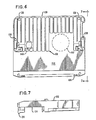
- Figs. 3 and 4 show elevational views of the body 50 of the cassette wherein the front view (Fig. 3) illustrates a two-degree angle of the ribbon path with respect to the line of printing for the purpose of making better use of the ribbon width.
- the cassette body 50 is formed to provide the entire ribbon path, including that portion of the ribbon 84 in the storage chamber or cavity 52 as well as the portion past the printing station, in a plane at two degrees from the line of printing, all as more specifically described in U.S. Patent No. 4,209,261.
- the side view in Fig. 4 also shows the latch members or lugs. 70 along with the spindles or hubs for the several rollers. It should be noted that the several spindles, pivot pins, and the like are generally molded as an integral part of the body 50 of the cassette.
- Fig. 5 is an enlarged elevation view of a portion of the re-inking mechanism shown in Fig. 2 and better illustrates the carriage 112 which has the upstanding hub 116 journaled on the pivot pin 118, the latter shown as being an integral part of the cassette body 50.
- the ink transfer roll 110 is freely journaled on the spindle 114 at the other end of the carriage 112 and is caused to be moved in a rockable manner toward and away from the ink roll 100 (Fig. 2) around the pivot pin 118.
- the extent of the rockable motion is relatively small as required by the amount of ink on the exterior periphery of the inktransfer roll 110 for re-inking the ribbon 84 and as determined by the tension in the ribbon 84 for providing the torque for rotating the transfer roll 110 and also the inking roll 100.
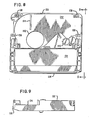
- Fig. 6 illustrates the top plan of a cover 130 for the cassette which fits onto the cassette body 50, shown in Fig. 2.
- the cover 130 has a ribbed portion 132 covering approximately the upper half of the cover and which portion generally matches the outline of the body 50.
- the ribbed portion 132 provides a design to present a pleasing appearance across the top of the cover 130 relative to the two-degree angle of the configuration of the cassette and of the path taken by the ribbon 84.
- the front portion 134 of the cover is generally plain and provides space for and covers the printing mechanism which may take the form of print wire solenoids, as more fully described in U.S. Patent No. 4,209,261.
- the front portion 134 also includes a tear-off edge 136, and several receptacles 138 are provided in the cover 130 for receiving the lugs 70 (Fig. 2).
- a recess 140 is provided in the cover 130 for accommodating the ribbon idler roller 80 while a further recess 142 in the cover accommodates the porous inking roll 100.
- the cassette includes the body 50 (Fig. 2) with the cover 130 (Fig. 6) fitting thereon to form the enclosure for the ribbon 84.
- Fig. 7 illustrates the shape of the cassette cover 130 as viewed in the direction from the right side of Fig. 6.
- the ribbed portion 132 covers the cassette body 50 and the plain portion 134 extends beyond the body to cover generally the printing mechanism (not shown) with which the ribbon cassette is associated.
- Fig. 8 shows the underside of the cassette cover 130 in an orientation opposite from the top plan view thereof in Fig. 6.
- the underside of the ribbed portion 132 of the cover 130 also shows the location of an upper ridge or dam 144 for association with the body 50 carried lower ridge or dam 115, of the inking roll recess 142 and of the idler roll recess 140 along with the receptacles 138 for receiving the lugs 70 on the cassette body 50.
- the frontal portion 134 and the tear-off edge 136 are also shown in the elevational view in Fig. 9 which is viewed from the right side of Fig. 8.
- the ribbon 84 which is preferably one-quarter inch (6mm) wide and formed in a loop approximately eighteen feet (5m) long, is loaded or stuffed into the cavity 52 but with a portion of the loop extending in the path around the roller 119 and around the ink transfer roll 110, along the printing station or line of printing generally in the vicinity of the tear-off edge 136, and then between the idler and drive rollers 80 and 82, which preferably drive the ribbon in continuous manner, and back into the chamber 52.
- the ink in the ribbon is being used or consumed in such operation.
- the ribbon is less saturated, or may become dry in a relative sense, and the frictional force between the less saturated ribbon and the ink transfer roll 110 increases along with a corresponding increase in ribbon tension resulting from the pull of the idler and drive rollers 80 and 82 and the increased frictional force.
- the increased ribbon tension causes the ribbon 84 to increase the pressure on or against the ink transfer roll 110 and to push or ease such roll in rockable manner against and in surface contact with the inking roll 100 with a greater force to effect an increased transfer of ink to the transfer roll and therefrom to the ribbon.
- the ribbon tension decreases in relative terms by reason of the ink saturated or wet condition since, in effect, such ribbon does not have as much frictional force in rotating the ink transfer roll 110.
- the effect of decreased ribbon tension and decreased frictional force reduces the amount or rate of ink transfer from the inking roll 100 to the transfer roll 110 by reason of the transfer roll 110 rocking or easing away from the inking roll 100. It is seen that a lesser amount of ink is transferred or lesser re-inking is necessary when the ribbon is relatively saturated and that a greater amount of ink is transferred or more re-inking is required when ink becomes depleted from the ribbon or when the ribbon is relatively less saturated. In this manner of operation, the re-inking process is self-regulating and, in effect, automatically re-inks the ribbon, dependent upon the ink saturated condition thereof.
- a ribbon cassette having a re-inking mechanism therein which utilizes increased and decreased tension in the ribbon itself to effect an increase and a decrease in the pressure of an ink transfer roll bearing against an inking roll in the manner of rocking motion of the ink transfer roll relative to the stationary inking roll.
Landscapes
- Impression-Transfer Materials And Handling Thereof (AREA)
Abstract
Description
- The invention relates to a ribbon cassette, and, in particular, to a self-regulating re-inking mechanism included therein.
- In present day printers, it is common practice to provide and use a ribbon cassette carrying an endless ribbon which is caused to be driven past a printing station, and wherein the printing ribbon is either a pre-inked and disposable ribbon or a ribbon which is to be continuously or frequently re-inked during the printing operation. The ribbon cassette itself may be of the stuffing-box type wherein the ribbon is contained within the cassette in random manner and such ribbon is unfolded at the cassette exit and caused to be driven past the printing station and then guided back into the cassette to be folded again in random manner therein.
- Additionally, a ribbon may be utilized in a mobius loop configuration within the cassette wherein the ribbon is in substantially continuous contact with an inking core or like member, or the ribbon may have a plurality of coils thereof around a central core for controlled inking or re-inking of the ribbon.
- European Patent Application No. 0,019,649 discloses a ribbon cassette containing an endless ribbon and having two ink supply rollers for re-inking purposes. Each supply roller has an associated ink transfer roller pivotally mounted on a lever and urged by a spring into frictional contact with the respecive ink supply roller. The ink transfer rollers serve as guides for the ribbon and transfer ink to the ribbon as it is advanced in contact therewith. A disadvantage of this arrangement is that the amount of ink transferred to the ribbon is independent of the actual ink requirement thereof, since the spring loading provides a substantially constant pressure of the ink transfer rollers on the ink supply rollers and, accordingly, a substantially uniform ink transfer to the ribbon.
- An arrangement in which the amount of ink transferred to the ribbon depends on the tension of the ribbon is disclosed in U.K. Patent Application No. 2,033,872. However, this arrangement uses a separate pressure element to sense ribbon tension for controlling the contact pressure of an inking wick on the ink transfer roller, and the arrangement, therefore, adjusts rather slowly to changing tension resulting from changes in ink condition of the ribbon. Also, the re-inking device including the pressure element and the wick does not form part of the ribbon cassette but is attachable thereto when a decline in print impression quality is detected.
- U.S. Patent No. 4,091,914 describes a ribbon cassette having a rotatably mounted ink supply roll and a transfer roller spaced therefrom and rotatable on an axle having an abrasive surface. The inner surface of the transfer roller is of a wear-susceptible material and as it is rotated by the ribbon on the axle, the wear-susceptible material is gradually worn away, thus increasing the inner diameter of the transfer roller and causing it to move towards, and eventually engage, the ink supply roll to provide a delayed and gradual replenishment or ink to the ribbon.
- It is an object of the present invention to provide a ribbon cassette whose re-inking mechanism forms an integral part of the cassette and is more sensitive and adjusts more quickly to changes in ink condition of the ribbon to regulate and automatically control the amount of ink that is made available and transferred to the ribbon.
- Thus, according to the invention, there is provided a ribbon cassette including an enclosure, an endless ribbon contained in said enclosure, driving means for moving the ribbon into and out of said enclosure for use in printing operations, an ink supply roll rotatably supported . at a fixed location within said enclosure, and an ink transfer roll rotatably mounted on a carriage which is pivotally mounted within said enclosure, said transfer roll being rockable to be brought into rotational contact with said ink supply roll for transferring ink from said ink supply roll to said ribbon, characterized in that said ink transfer roll is arranged to be moved by the ribbon relative to said ink supply roll, whereby an increased tension in said ribbon indicating depletion of ink therein causes increased pressure on said ink supply roll to increase transfer of ink to said ribbon and whereby a decreased tension in said ribbon indicating a saturated ink condition in said ribbon causes decreased pressure on said ink supply roll to decrease transfer of ink to said ribbon.
- Embodiments of the invention will now be described, by way of example, with reference to the accompanying drawings, in which:
- Fig. 1 is a plan view of a portion of a ribbon cassette according to the invention illustrating a ribbon re-inking mechanism;
- Fig. 2 is a top plan view of the body of a ribbon cassette having the cover removed to show the interior structure;
- Fig. 3 is a front elevational view taken along the line 3-3 of Fig. 2;
- Fig. 4 is a side elevational view taken along the line 4-4 of Fig. 2;
- Fig. 5 is an enlarged elevational view of a portion of the re-inking mechanism shown in Fig. 2;
- Fig. 6 is a top plan view of the cover of the cassette shown in Fig. 2;
- Fig. 7 is a side elevational view taken along the line 7-7 of Fig. 6;
- Fig. 8 is a plan view of the underside of the cassette cover shown in Fig. 6; and
- Fig. 9 is a side elevational view taken along the line 9-9 of Fig. 8.
- Fig. 1 shows a portion of a
ribbon cassette 10 providing space for a re-inking mechanism which includes a porousrubber inking roll 12 journaled on a fixed-position shaft orspindle 32. Atransfer roll 18 is rotatably mounted on and carried by acarrier 36 which is journaled on a pivot orspindle 38 and whichroll 18 is normally in surface contact with theinking roll 12. Asingle guidepost 40 is provided upstream of thetransfer roll 18 to cause theribbon 20 to travel along a path just short of halfway around the periphery of thetransfer roll 18. - The pivoting of the
transfer roll 18 relative to and into pressure contact with theinking roll 12 utilizes theribbon 20 itself to maintain such contact. As the ink in theribbon 20 is used or depleted therefrom, the ribbon tension increases by reason of the drying condition, which increased tension, in turn, causes theribbon 20 to urge thetransfer roll 18 against theinking roll 12 with a greater force and thereby cause more or faster transfer of ink from theinking roll 12 to thetransfer roll 18. As thetransfer roll 18 becomes more saturated with the ink, the ribbon tension decreases by reason of the ink wetting condition thereof and relieves the urging of thetransfer roll 18 against theinking roll 12 in a manner which regulates the amount of ink that is transferred from theinking roll 12 to the transfer roll-18. The result is less re-inking in the case of a saturated ribbon condition and more re-inking as the ink is depleted from theribbon 20. In this manner and arrangement, it is seen that the re-inking mechanism provides for self-regulation and control of the amount of ink which is transferred from theinking roll 12 to thetransfer roll 18 so as to maintain a properly inkedribbon 20. - It should be clear that the arrangement of the re-inking mechanism within the
ribbon cassette 10, as specifically shown in Fig. 1, could be of any one of a number of different forms, depending upon the particular design of the ribbon cassette. - Fig. 2 is a top plan view of the body of a ribbon cassette having the cover removed therefrom to show the interior stucture and the various components thereof in a preferred arrangement of the subject matter of the present invention.
Such cassette body 50 is preferably of molded plastic material and takes the shape of a generally rectangular flat case for supporting the ribbon thereof and which is adapted to fit adjacent or along the printing station of a printer. As shown, thecassette body 50 includes a large cavity orchamber 52 formed in part by an outer wall starting at the right side of the cassette and having awall portion 54 curving toward the rear of the cassette, awall portion 56 running along the rear of the cassette, and awall portion 58 curving toward the front of the cassette near the left side thereof. A generally centrally-locatedwall 60 extends for a distance through thecassette body 50 and a slanted orinclined wall 62 is connected with and is directed from one end of thewall 60 at an angle downwardly and toward the front of the body of the cassette. Thewall 62 continues to form awall portion 64 along the front of the cassette body and toward the right side thereof. Ashort wall portion 66 and anotherwall portion 68 are located between thewall portion 64 and the start of thewall portion 54. - A plurality of latch members or
lugs 70 are formed as an integral part of the cassette body and are positioned generally at the four corners thereof for connection and attachment to mating receptacles in the cover of the cassette. A front guide or locatingfinger 72 is provided as an integral part of thecassette body 50 for aid in connecting the cassette cover with such body. It is understood, of course, that the cassette includes thebody 50 with the cover (later described) connected to form the enclosure for the ribbon. - The internal components of the
body 50 of the cassette include a pair ofrollers ribbon 84 at the entrance end of the cassette, in the direction indicated by thearrow 86, and into the cavity orchamber 52. It is, of course, to be noted that, while theribbon 84 is shown as a single strand within thecavity 52, the ribbon is folded many times in a stuffing manner to substantially fill the cavity. Theroller 82 is preferably the drive roller and is connected to a drive member (not shown) while theidler roller 80 is maintained in a biased position againstsuch roller 82 by means of aspring 88 wrapped around a stud orpin 90 and having one end thereof engageable against one end of a support arm 92 pivoted on a spindle or ashaft 94. The other end of thespring 88 engages anextension 96 of thewall 62, whereby the arm 92 is thus urged against theidler roller 80 which, in turn, is urged against thedrive roller 82 by action of thespring 88 to provide a precise drive for theribbon 84. As is well-known in the art, the support arm 92 may include a plurality of stripper bearings which are positioned to mate with and extend between the several ribbon driving portions of theidler roller 80. - A ribbon re-inking mechanism is provided and supported within the
cassette body 50 adjacent theribbon 84 exit at the right side thereof. A porous-rubber inking roll 100 is rotatably carried or journaled on ahub 101 supported from aspindle 102 positioned in a cavity orchamber 104 formed by thewalls ink transfer roll 110 preferably of plastic material is supported from and carried on acarriage 112 at the right ofinking roll 100. Thecarriage 112 includes aspindle 114 at one end thereof for rotatably carrying thetransfer roll 110 and includes ahub 116 at the other end thereof seated on a pivot pin orspindle 118. A roller or likebearing 119 is positioned and journaled on aspindle 120 adjacent thewall portion 54. Thecarriage 112 with theink transfer roll 110 thereon is journaled or pivoted on thespindle 118 to enable the transfer roll to surface engage with theinking roll 100 in increasing or decreasing pressure conditions. - The
ribbon 84 is contained within the cavity orchamber 52 in a random or stuffing manner and is caused to be pulled across a lower ridge ordam 115 and then directed by awall portion 122 formed as an end of thewall 60 to take a path around thebearing 119. From such bearing 119, theribbon 84 is directed around aguidepost 124 and then around thetransfer roll 110 with sufficient tension therein to cause rotation of the transfer roll along with rotation of theinking roll 100. Thespindle 114 provides a loose fit for ease of rotation of thetransfer roll 110. Theribbon 84 is directed past the exit of thecassette body 50 and along the printing station (not shown) and then is positioned between therollers storage chamber 52. The path of the ribbon is shown along with an indication of the direction of rotation of the several rollers by means of appropriate arrows in Fig. 2. - Figs. 3 and 4 show elevational views of the
body 50 of the cassette wherein the front view (Fig. 3) illustrates a two-degree angle of the ribbon path with respect to the line of printing for the purpose of making better use of the ribbon width. Thecassette body 50 is formed to provide the entire ribbon path, including that portion of theribbon 84 in the storage chamber orcavity 52 as well as the portion past the printing station, in a plane at two degrees from the line of printing, all as more specifically described in U.S. Patent No. 4,209,261. The side view in Fig. 4 also shows the latch members or lugs. 70 along with the spindles or hubs for the several rollers. It should be noted that the several spindles, pivot pins, and the like are generally molded as an integral part of thebody 50 of the cassette. - Fig. 5 is an enlarged elevation view of a portion of the re-inking mechanism shown in Fig. 2 and better illustrates the
carriage 112 which has theupstanding hub 116 journaled on thepivot pin 118, the latter shown as being an integral part of thecassette body 50. Theink transfer roll 110 is freely journaled on thespindle 114 at the other end of thecarriage 112 and is caused to be moved in a rockable manner toward and away from the ink roll 100 (Fig. 2) around thepivot pin 118. It must be realized, of course, that the extent of the rockable motion is relatively small as required by the amount of ink on the exterior periphery of theinktransfer roll 110 for re-inking theribbon 84 and as determined by the tension in theribbon 84 for providing the torque for rotating thetransfer roll 110 and also the inkingroll 100. - Fig. 6 illustrates the top plan of a
cover 130 for the cassette which fits onto thecassette body 50, shown in Fig. 2. Thecover 130 has a ribbedportion 132 covering approximately the upper half of the cover and which portion generally matches the outline of thebody 50. Theribbed portion 132 provides a design to present a pleasing appearance across the top of thecover 130 relative to the two-degree angle of the configuration of the cassette and of the path taken by theribbon 84. Thefront portion 134 of the cover is generally plain and provides space for and covers the printing mechanism which may take the form of print wire solenoids, as more fully described in U.S. Patent No. 4,209,261. Thefront portion 134 also includes a tear-off edge 136, andseveral receptacles 138 are provided in thecover 130 for receiving the lugs 70 (Fig. 2). Arecess 140 is provided in thecover 130 for accommodating the ribbonidler roller 80 while afurther recess 142 in the cover accommodates theporous inking roll 100. As briefly alluded to earlier herein, the cassette includes the body 50 (Fig. 2) with the cover 130 (Fig. 6) fitting thereon to form the enclosure for theribbon 84. - Fig. 7 illustrates the shape of the
cassette cover 130 as viewed in the direction from the right side of Fig. 6. Theribbed portion 132 covers thecassette body 50 and theplain portion 134 extends beyond the body to cover generally the printing mechanism (not shown) with which the ribbon cassette is associated. - Fig. 8 shows the underside of the
cassette cover 130 in an orientation opposite from the top plan view thereof in Fig. 6. The underside of theribbed portion 132 of thecover 130 also shows the location of an upper ridge ordam 144 for association with thebody 50 carried lower ridge ordam 115, of the inkingroll recess 142 and of theidler roll recess 140 along with thereceptacles 138 for receiving thelugs 70 on thecassette body 50. Thefrontal portion 134 and the tear-off edge 136 are also shown in the elevational view in Fig. 9 which is viewed from the right side of Fig. 8. - In the operation of the ribbon cassette and the re-inking mechanism therein, the
ribbon 84, which is preferably one-quarter inch (6mm) wide and formed in a loop approximately eighteen feet (5m) long, is loaded or stuffed into thecavity 52 but with a portion of the loop extending in the path around theroller 119 and around theink transfer roll 110, along the printing station or line of printing generally in the vicinity of the tear-off edge 136, and then between the idler and driverollers chamber 52. - As the
ribbon 84 is being subjected to impact by the printing elements (such as print wires) during the printing operation, the ink in the ribbon is being used or consumed in such operation. As ink is depleted from theribbon 84, the ribbon is less saturated, or may become dry in a relative sense, and the frictional force between the less saturated ribbon and theink transfer roll 110 increases along with a corresponding increase in ribbon tension resulting from the pull of the idler and driverollers ribbon 84 to increase the pressure on or against theink transfer roll 110 and to push or ease such roll in rockable manner against and in surface contact with the inkingroll 100 with a greater force to effect an increased transfer of ink to the transfer roll and therefrom to the ribbon. - As the
ribbon 84 becomes more saturated with an increased transfer of ink thereto, the ribbon tension decreases in relative terms by reason of the ink saturated or wet condition since, in effect, such ribbon does not have as much frictional force in rotating theink transfer roll 110. The effect of decreased ribbon tension and decreased frictional force reduces the amount or rate of ink transfer from the inkingroll 100 to thetransfer roll 110 by reason of thetransfer roll 110 rocking or easing away from the inkingroll 100. It is seen that a lesser amount of ink is transferred or lesser re-inking is necessary when the ribbon is relatively saturated and that a greater amount of ink is transferred or more re-inking is required when ink becomes depleted from the ribbon or when the ribbon is relatively less saturated. In this manner of operation, the re-inking process is self-regulating and, in effect, automatically re-inks the ribbon, dependent upon the ink saturated condition thereof. - It is thus seen that herein shown and described is a ribbon cassette having a re-inking mechanism therein which utilizes increased and decreased tension in the ribbon itself to effect an increase and a decrease in the pressure of an ink transfer roll bearing against an inking roll in the manner of rocking motion of the ink transfer roll relative to the stationary inking roll.
Claims (8)
Applications Claiming Priority (2)
| Application Number | Priority Date | Filing Date | Title |
|---|---|---|---|
| US37482382A | 1982-05-04 | 1982-05-04 | |
| US374823 | 1982-05-04 |
Publications (2)
| Publication Number | Publication Date |
|---|---|
| EP0107719A1 EP0107719A1 (en) | 1984-05-09 |
| EP0107719B1 true EP0107719B1 (en) | 1986-07-23 |
Family
ID=23478327
Family Applications (1)
| Application Number | Title | Priority Date | Filing Date |
|---|---|---|---|
| EP19830901866 Expired EP0107719B1 (en) | 1982-05-04 | 1983-04-26 | Ribbon cassette |
Country Status (4)
| Country | Link |
|---|---|
| EP (1) | EP0107719B1 (en) |
| CA (1) | CA1203431A (en) |
| DE (1) | DE3364675D1 (en) |
| WO (1) | WO1983003798A1 (en) |
Families Citing this family (1)
| Publication number | Priority date | Publication date | Assignee | Title |
|---|---|---|---|---|
| US5487615A (en) * | 1994-10-28 | 1996-01-30 | Sercomp Corporation | Ribbon drive assembly for ribbon cartridge |
Family Cites Families (3)
| Publication number | Priority date | Publication date | Assignee | Title |
|---|---|---|---|---|
| GB1459071A (en) * | 1974-04-30 | 1976-12-22 | Ncr Co | Ink ribbon device |
| US4091914A (en) * | 1977-02-22 | 1978-05-30 | Porelon, Inc. | Wear-activated ribbon reinker |
| EP0031854A1 (en) * | 1979-12-27 | 1981-07-15 | Mannesmann Kienzle GmbH | Ink ribbon cartridge with a reinking device and method of manufacturing this cartridge |
-
1983
- 1983-04-21 CA CA000426461A patent/CA1203431A/en not_active Expired
- 1983-04-26 WO PCT/US1983/000613 patent/WO1983003798A1/en active IP Right Grant
- 1983-04-26 EP EP19830901866 patent/EP0107719B1/en not_active Expired
- 1983-04-26 DE DE8383901866T patent/DE3364675D1/en not_active Expired
Also Published As
| Publication number | Publication date |
|---|---|
| CA1203431A (en) | 1986-04-22 |
| DE3364675D1 (en) | 1986-08-28 |
| EP0107719A1 (en) | 1984-05-09 |
| WO1983003798A1 (en) | 1983-11-10 |
Similar Documents
| Publication | Publication Date | Title |
|---|---|---|
| EP0153388B1 (en) | Ribbon cassette for use in a printer | |
| US4536098A (en) | Self-regulating ribbon re-inking device | |
| US4653947A (en) | Reinking device for ribbon cartridge | |
| CA1053639A (en) | Ribbon drive means | |
| CA2106738C (en) | Thermal printing postage meter system | |
| US4390294A (en) | Ribbon re-inking machine capable of reloading a variety of types of ribbon cassettes | |
| EP0105136B1 (en) | Inking ribbon cartridge and printing apparatus for use therewith | |
| US4273453A (en) | Selectively engageable ribbon re-inking device for ink ribbon cartridge | |
| US4109790A (en) | Supporting cover for an ink roll means | |
| US4053042A (en) | Endless ribbon cartridge | |
| JPH0651417B2 (en) | Ribbon cartridge | |
| EP0107719B1 (en) | Ribbon cassette | |
| US5329302A (en) | Tapered platen roller for thermal printer | |
| CA1314855C (en) | High-symbol density printer cartridge | |
| JPS59500709A (en) | ribbon cassette | |
| US4840502A (en) | Thermal transfer ribbon cassette | |
| US3186337A (en) | Tape coding attachment | |
| JPH0536705Y2 (en) | ||
| CA1334564C (en) | Cartridge for an inked ribbon with a re-inking device | |
| JPS5914208Y2 (en) | Cartridge for endless ink ribbon | |
| JPH0214439Y2 (en) | ||
| JPS60244581A (en) | Ink ribbon sub-cartridge | |
| JPS6014593Y2 (en) | typewriter ribbon cassette | |
| JPH043820Y2 (en) | ||
| JPH0418862Y2 (en) |
Legal Events
| Date | Code | Title | Description |
|---|---|---|---|
| PUAI | Public reference made under article 153(3) epc to a published international application that has entered the european phase |
Free format text: ORIGINAL CODE: 0009012 |
|
| AK | Designated contracting states |
Designated state(s): DE FR GB |
|
| 17P | Request for examination filed |
Effective date: 19840427 |
|
| DET | De: translation of patent claims | ||
| GRAA | (expected) grant |
Free format text: ORIGINAL CODE: 0009210 |
|
| AK | Designated contracting states |
Kind code of ref document: B1 Designated state(s): DE FR GB |
|
| REF | Corresponds to: |
Ref document number: 3364675 Country of ref document: DE Date of ref document: 19860828 |
|
| ET | Fr: translation filed | ||
| PLBE | No opposition filed within time limit |
Free format text: ORIGINAL CODE: 0009261 |
|
| STAA | Information on the status of an ep patent application or granted ep patent |
Free format text: STATUS: NO OPPOSITION FILED WITHIN TIME LIMIT |
|
| 26N | No opposition filed | ||
| PGFP | Annual fee paid to national office [announced via postgrant information from national office to epo] |
Ref country code: FR Payment date: 19890428 Year of fee payment: 7 |
|
| PGFP | Annual fee paid to national office [announced via postgrant information from national office to epo] |
Ref country code: GB Payment date: 19890430 Year of fee payment: 7 |
|
| PGFP | Annual fee paid to national office [announced via postgrant information from national office to epo] |
Ref country code: DE Payment date: 19890502 Year of fee payment: 7 |
|
| PG25 | Lapsed in a contracting state [announced via postgrant information from national office to epo] |
Ref country code: GB Effective date: 19900426 |
|
| PG25 | Lapsed in a contracting state [announced via postgrant information from national office to epo] |
Ref country code: FR Effective date: 19901228 |
|
| PG25 | Lapsed in a contracting state [announced via postgrant information from national office to epo] |
Ref country code: DE Effective date: 19910101 |
|
| GBPC | Gb: european patent ceased through non-payment of renewal fee | ||
| REG | Reference to a national code |
Ref country code: FR Ref legal event code: ST |