EP0107641A2 - Wirbelströmungsmessgerät - Google Patents
Wirbelströmungsmessgerät Download PDFInfo
- Publication number
- EP0107641A2 EP0107641A2 EP83870111A EP83870111A EP0107641A2 EP 0107641 A2 EP0107641 A2 EP 0107641A2 EP 83870111 A EP83870111 A EP 83870111A EP 83870111 A EP83870111 A EP 83870111A EP 0107641 A2 EP0107641 A2 EP 0107641A2
- Authority
- EP
- European Patent Office
- Prior art keywords
- sensor
- flow meter
- supporting portion
- strain relief
- sensor supporting
- Prior art date
- Legal status (The legal status is an assumption and is not a legal conclusion. Google has not performed a legal analysis and makes no representation as to the accuracy of the status listed.)
- Granted
Links
Images

Classifications
-
- G—PHYSICS
- G01—MEASURING; TESTING
- G01F—MEASURING VOLUME, VOLUME FLOW, MASS FLOW OR LIQUID LEVEL; METERING BY VOLUME
- G01F1/00—Measuring the volume flow or mass flow of fluid or fluent solid material wherein the fluid passes through a meter in a continuous flow
- G01F1/05—Measuring the volume flow or mass flow of fluid or fluent solid material wherein the fluid passes through a meter in a continuous flow by using mechanical effects
- G01F1/20—Measuring the volume flow or mass flow of fluid or fluent solid material wherein the fluid passes through a meter in a continuous flow by using mechanical effects by detection of dynamic effects of the flow
- G01F1/32—Measuring the volume flow or mass flow of fluid or fluent solid material wherein the fluid passes through a meter in a continuous flow by using mechanical effects by detection of dynamic effects of the flow using swirl flowmeters
- G01F1/3209—Measuring the volume flow or mass flow of fluid or fluent solid material wherein the fluid passes through a meter in a continuous flow by using mechanical effects by detection of dynamic effects of the flow using swirl flowmeters using Karman vortices
Definitions
- This invention relates to a volumetric flow meter, and more particularly, to an improved vortex flow meter.
- Volumetric flow meters such as vortex flow meters have employed strain gauges, capacitors, piezoelectric disks and the like as flow sensors. Meters of this type have often been sensitive to strain induced by external vibration. The strain has reached the meters through the piping in which the meters have been located, from vibration sources such as wind, control valve turbulence, and reciprocating machinery including compressors and pumps. Transmission of the vibration to the flow sensors has caused strain in the sensors, resulting in erroneous sensor outputs.
- Another object is to accomplish the sensitivity reduction by actually reducing the strain transmitted to the sensors, rather than electronically conditioning the sensor signal, to permit the employment of simpler, less expensive electronic circuitry.
- this invention is, in principal aspect, an improved flow meter, and an improved sensor body for a flow meter.
- the sensor body has a mounting portion, a flow sensor supporting portion and a strain relief portion.
- the strain relief portion is preferably located intermediate the mounting portion and the sensor supporting portion, and is adapted, as by reduction of stiffness, to relieve induced strain of the sensor supporting portion.
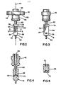
- FIGS. The preferred embodiment of the invention is described below in relation to the accompanying drawing. Briefly, the drawing includes five figures, or FIGS., as follows:
- the preferred embodiment of the invention is both an improved flow meter 10 and an improved sensor body 12 which may also function as a vortex shedding bluff body.
- the sensor body 12 is a part of the flow meter 10, which is joined by a signal conditioner 14 to form a flow transmitter 16.
- the meter 10 employs piezoelectric disks such as disk 18 as its sensors.
- the conditioner 14 is cantilevered atop the meter 10 by a bracket 20, and electrical circuitry such as sensor leads 22 join the disks 18 and the conditioner 14.
- the leads 22 pass through an internal circuitry passage 24 in the body 12 and inside a flexible bellows 26, to reach the conditioner 14.
- Detailed information about the disks 18 is provided in European Patent Application Publication No. 0077 764.
- the meter 10 Concentrating on the meter 10 and body 12, the meter 10 includes a housing 27 of two flanges 28, 30 and a central section 32. Two mounting plates, or bosses, 34, 36 are provided atop the section 32, for mounting of the sensor body 12. A sensor body opening 38 opens into the central fluid passage 40 within the section 32.
- the sensor body 12 includes a mounting portion 42.
- the body 12 extends along a central axis 44, as shown in FIG. 2, and the mounting portion 42 includes a flange 46 extending generally perpendicular to the axis 44.
- the flange 46 provides two fastening areas 48, 50, where fasteners such as the bolts 52, 54 of FIG. 1 are employed to mount and fasten the flange 46, and thereby the body 12, to the mounting plates 34, 36, and thereby the meter housing 27.
- a cylindrical section 56 of the mounting portion 42 extends between the plates 34, 36 from the flange 46 to the upper surface of the housing central section 32. When the body 12 is mounted, the section 56 caps the opening 38.
- the sensor body 12 includes a sensor supporting portion 58, an intermediate, strain relief portion 60 and a bottom, retained end 62.
- the portion 60 is intermediate the portions 42, 58 in that it is between the portions 42, 58. This intermediate location is the preferred location, although it is believed other locations may be possible.
- the sensor supporting portion 58 is rectangular, as best shown in FIG. 5.
- the portion 58 includes opposed sidewalls 64, 66 and endwalls 68, 70.
- the sidewalls 64, 66 define sensor receiving recesses 72, 74.
- the circuitry passage 24 terminates at the recesses 72, 74.
- the sensor supporting portion 58 Adjacent the strain relief portion 60, the sensor supporting portion 58 includes an enlarged, generally cylindrical area 76.
- the opposed bottom surfaces 78, 80 of the area 76 above the endwalls 68, 70 are concave, to blend with the contour of the inner wall of the housing central section 32.
- the sensor supporting portion 58 when the sensor body 12 is properly located in the housing 27, the sensor supporting portion 58 is in the central fluid passage 40, while the enlarged area 76 loosely fits the opening 28-, to protect the strain relief portion 60 from fluid turbulence, and to create continuity in the contour of the housing inner wall. Continuity eliminates disruption of the Von Karman vortex street in the fluid passage 40.
- the strain relief portion 60 is thus within the opening 28.
- the strain relief portion 60 is outwardly cylindrical, and as shown in FIGS. 1 and 4, annular.
- the portion 60 is adapted to relieve strain in the sensor supporting portion 58 from external vibration.
- bending moments induced on piping have been the cause of strain on the flow sensors.
- the moments result in sensor body deflections in the order of hundredths of a micron. These deflections, while nearly infintesimal, cause the sensor strain.
- the strain relief portion 60 "absorbs" these deflections, leaving the portion 58 only insignificantly deflected.
- the strain relief portion 60 has a stiffness substantially less than that of the sensor supporting portion 58.
- the portion 60 acts as a spring.
- the stiffness would be zero and the portion 60 would absorb all of the deflections.
- the tolerable deflection of the portion 58 is established for the particular sensors in use, and the portion 60 configured to transmit no more than this deflection.
- Axial stresses, hydrostatic stresses, operating temperature, material choice and fatigue are also accommodated.
- a smaller circuitry opening 24, an axially longer portion 60 and a thinner portion 60 are preferred.
- the following characteristics of the portion 60 have been found acceptable: for a pipe size ("size") of 25 mm, a nominal outer diameter (OD) of 5.26 mm; a nominal inner diameter (ID) of 3.18 mm, and a nominal length (L) of 15.24 mm; for a size of 40 mm, an OD of 7.82 mm; an ID of 4.78 mm, and an L of 17.78 mm; for a size of 50 mm, an OD of 9.14 mm, an ID of 6.60 mm, and an L of 17.78 mm; for a size of 80 mm, an OD of 11.18 mm, an ID of 6.60 mm, and an L of 15.24 mm; for a size of 100 mm, an OD of 15.75 mm; an ID of 12.70 mm, and an L of 12.70 mm; and for a size of 150 mm, an OD of 21.44 mm, an ID of 15.85 mm, and an L of 17.78 mm. Tolerances are
- the outer dimension of the portion 60 is substantially less than the outer dimensions of the portion 58.
- the strain relief portion 60 is cylindrical, but it will be understood that other shapes may be utilized. Strain relief with such other shapes may be accomplished by having the dimensions of the strain relief portion 60 in the planes of vibration being substantially less than the corresponding dimensions of the sensor supporting portion 58 in the planes of vibration. For example, as shown in Fig 3, the width of the end walls 68, 70 is substantially greater than the corresponding dimension of the strain relief portion 60.
Landscapes
- Physics & Mathematics (AREA)
- Fluid Mechanics (AREA)
- General Physics & Mathematics (AREA)
- Measuring Volume Flow (AREA)
- Details Of Flowmeters (AREA)
Applications Claiming Priority (2)
| Application Number | Priority Date | Filing Date | Title |
|---|---|---|---|
| US436426 | 1982-10-25 | ||
| US06/436,426 US4487076A (en) | 1982-10-25 | 1982-10-25 | Vortex flow meter |
Publications (3)
| Publication Number | Publication Date |
|---|---|
| EP0107641A2 true EP0107641A2 (de) | 1984-05-02 |
| EP0107641A3 EP0107641A3 (en) | 1984-12-12 |
| EP0107641B1 EP0107641B1 (de) | 1988-01-07 |
Family
ID=23732353
Family Applications (1)
| Application Number | Title | Priority Date | Filing Date |
|---|---|---|---|
| EP83870111A Expired EP0107641B1 (de) | 1982-10-25 | 1983-10-20 | Wirbelströmungsmessgerät |
Country Status (6)
| Country | Link |
|---|---|
| US (1) | US4487076A (de) |
| EP (1) | EP0107641B1 (de) |
| JP (1) | JPS5995424A (de) |
| AU (1) | AU555509B2 (de) |
| CA (1) | CA1200403A (de) |
| DE (1) | DE3375204D1 (de) |
Cited By (1)
| Publication number | Priority date | Publication date | Assignee | Title |
|---|---|---|---|---|
| EP0581163A1 (de) * | 1992-07-20 | 1994-02-02 | Oval Corporation | Wirbeldurchflussmesser |
Families Citing this family (5)
| Publication number | Priority date | Publication date | Assignee | Title |
|---|---|---|---|---|
| JPS61153329A (ja) * | 1984-12-25 | 1986-07-12 | Fuji Kogyo Kk | レンジフ−ド |
| US7793554B2 (en) * | 2009-02-05 | 2010-09-14 | Masco Corporation | Flexible sensor flow and temperature detector |
| US9140586B2 (en) * | 2012-09-25 | 2015-09-22 | General Electric Company | Removable sensor port insert apparatus |
| US9574680B2 (en) * | 2014-07-16 | 2017-02-21 | Castlebridge Enterprises, Inc. | Water safety shut-off valve |
| CN114776279A (zh) * | 2022-04-26 | 2022-07-22 | 克拉玛依四维石油科技有限公司 | 一种低温高压超临界二氧化碳井下流量计 |
Family Cites Families (10)
| Publication number | Priority date | Publication date | Assignee | Title |
|---|---|---|---|---|
| US3908458A (en) * | 1973-11-12 | 1975-09-30 | American Chain & Cable Co | Open channel flow measuring device |
| DE2458901C3 (de) * | 1974-04-23 | 1986-07-10 | The Foxboro Co., Foxboro, Mass. | Strömungsmesser |
| US3972232A (en) * | 1974-04-24 | 1976-08-03 | The Foxboro Company | Vortex flow meter apparatus |
| US4005604A (en) * | 1975-09-30 | 1977-02-01 | Fischer & Porter Co. | Non-contact sensor for vortex-type flowmeter |
| US4003251A (en) * | 1976-03-19 | 1977-01-18 | Fischer & Porter Co. | Acceleration-proof vortex-type flowmeter |
| GB1601548A (en) * | 1977-05-30 | 1981-10-28 | Yokogawa Electric Works Ltd | Flow metering apparatus |
| US4329880A (en) * | 1979-05-10 | 1982-05-18 | Fischer & Porter Co. | Vortex-shedding flowmeter with torsional sensor mounted on torque tube |
| JPS6029046B2 (ja) * | 1980-01-24 | 1985-07-08 | 横河電機株式会社 | 流速流量測定装置 |
| US4339957A (en) * | 1980-08-14 | 1982-07-20 | Fischer & Porter Company | Vortex-shedding flowmeter with unitary shedder/sensor |
| IT1204503B (it) * | 1987-03-11 | 1989-03-03 | Montedipe Spa | Processo per la sintesi dell'epsiloncaprolattame |
-
1982
- 1982-10-25 US US06/436,426 patent/US4487076A/en not_active Expired - Fee Related
-
1983
- 1983-10-20 DE DE8383870111T patent/DE3375204D1/de not_active Expired
- 1983-10-20 EP EP83870111A patent/EP0107641B1/de not_active Expired
- 1983-10-24 CA CA000439543A patent/CA1200403A/en not_active Expired
- 1983-10-24 AU AU20498/83A patent/AU555509B2/en not_active Ceased
- 1983-10-24 JP JP58198950A patent/JPS5995424A/ja active Pending
Cited By (2)
| Publication number | Priority date | Publication date | Assignee | Title |
|---|---|---|---|---|
| EP0581163A1 (de) * | 1992-07-20 | 1994-02-02 | Oval Corporation | Wirbeldurchflussmesser |
| US5363705A (en) * | 1992-07-20 | 1994-11-15 | Oval Corporation | Vortex generator having a protrusion formed at an upstream surface |
Also Published As
| Publication number | Publication date |
|---|---|
| JPS5995424A (ja) | 1984-06-01 |
| AU2049883A (en) | 1984-05-03 |
| AU555509B2 (en) | 1986-09-25 |
| DE3375204D1 (en) | 1988-02-11 |
| CA1200403A (en) | 1986-02-11 |
| US4487076A (en) | 1984-12-11 |
| EP0107641B1 (de) | 1988-01-07 |
| EP0107641A3 (en) | 1984-12-12 |
Similar Documents
| Publication | Publication Date | Title |
|---|---|---|
| US4791818A (en) | Cantilever beam, insertable, vortex meter sensor | |
| US5463904A (en) | Multimeasurement vortex sensor for a vortex-generating plate | |
| EP1733192B1 (de) | Skalierbares mittelndes einsteck-wirbeldurchflussmessgerät | |
| AU616499B2 (en) | Rocking beam vortex sensor | |
| KR0133502B1 (ko) | 전자유량계 | |
| CA1157294A (en) | Vortex-shedding flowmeter having two bluff bodies | |
| EP0666468A2 (de) | Ersetzbarer Wirbelsensor für mehrfache Messung | |
| US4703659A (en) | Vortex shedding flow meter with noise suppressing and signal enhancing means | |
| EP0107641A2 (de) | Wirbelströmungsmessgerät | |
| EP0144937B1 (de) | Wirbeldurchflussmesser | |
| CA1063385A (en) | External-sensor vortex-type flowmeter | |
| US4976156A (en) | Impulse sensor with balanced mass-stiffness distribution | |
| US5804740A (en) | Capacitive vortex mass flow sensor | |
| EP0218216A1 (de) | Luftdurchflussmengenmesser | |
| US5233862A (en) | Apparatus for determining the torque exerted on a sealing ring that seals a duct gap between a housing and a shaft | |
| US5214965A (en) | Vortex generator-sensor with noise cancelling transducer | |
| EP0417058A1 (de) | Kraftübertragende Vorrichtung für einen Wirbel-Durchflussmesser | |
| US4380935A (en) | External sensing vortex flowmeter | |
| US4926532A (en) | Method of manufacturing a flow meter | |
| US4116058A (en) | Contoured obstacle assembly for vortex-type flowmeter | |
| US5186056A (en) | Vortex flowmeter with dual vortex sensors | |
| EP0450563A1 (de) | Thermischer Luftmengenmesser | |
| US4627285A (en) | Pointer for liquid filled gauges | |
| EP0161929B1 (de) | Balken für Kraftwandler | |
| CN2271708Y (zh) | 耐强腐隔膜压力表 |
Legal Events
| Date | Code | Title | Description |
|---|---|---|---|
| PUAI | Public reference made under article 153(3) epc to a published international application that has entered the european phase |
Free format text: ORIGINAL CODE: 0009012 |
|
| AK | Designated contracting states |
Designated state(s): DE FR GB IT NL |
|
| PUAL | Search report despatched |
Free format text: ORIGINAL CODE: 0009013 |
|
| AK | Designated contracting states |
Designated state(s): DE FR GB IT NL |
|
| 17P | Request for examination filed |
Effective date: 19850508 |
|
| 17Q | First examination report despatched |
Effective date: 19861015 |
|
| RAP1 | Party data changed (applicant data changed or rights of an application transferred) |
Owner name: FISHER CONTROLS INTERNATIONAL, INC. |
|
| GRAA | (expected) grant |
Free format text: ORIGINAL CODE: 0009210 |
|
| AK | Designated contracting states |
Kind code of ref document: B1 Designated state(s): DE FR GB IT NL |
|
| REF | Corresponds to: |
Ref document number: 3375204 Country of ref document: DE Date of ref document: 19880211 |
|
| ET | Fr: translation filed | ||
| ITF | It: translation for a ep patent filed | ||
| PLBE | No opposition filed within time limit |
Free format text: ORIGINAL CODE: 0009261 |
|
| STAA | Information on the status of an ep patent application or granted ep patent |
Free format text: STATUS: NO OPPOSITION FILED WITHIN TIME LIMIT |
|
| 26N | No opposition filed | ||
| PGFP | Annual fee paid to national office [announced via postgrant information from national office to epo] |
Ref country code: FR Payment date: 19900910 Year of fee payment: 8 |
|
| PGFP | Annual fee paid to national office [announced via postgrant information from national office to epo] |
Ref country code: GB Payment date: 19900912 Year of fee payment: 8 |
|
| PGFP | Annual fee paid to national office [announced via postgrant information from national office to epo] |
Ref country code: DE Payment date: 19900928 Year of fee payment: 8 |
|
| ITTA | It: last paid annual fee | ||
| PGFP | Annual fee paid to national office [announced via postgrant information from national office to epo] |
Ref country code: NL Payment date: 19901031 Year of fee payment: 8 |
|
| PG25 | Lapsed in a contracting state [announced via postgrant information from national office to epo] |
Ref country code: GB Effective date: 19911020 |
|
| PG25 | Lapsed in a contracting state [announced via postgrant information from national office to epo] |
Ref country code: NL Effective date: 19920501 |
|
| NLV4 | Nl: lapsed or anulled due to non-payment of the annual fee | ||
| GBPC | Gb: european patent ceased through non-payment of renewal fee | ||
| PG25 | Lapsed in a contracting state [announced via postgrant information from national office to epo] |
Ref country code: FR Effective date: 19920630 |
|
| PG25 | Lapsed in a contracting state [announced via postgrant information from national office to epo] |
Ref country code: DE Effective date: 19920701 |
|
| REG | Reference to a national code |
Ref country code: FR Ref legal event code: ST |