EP0107280A2 - Apparat zur Führung eines Kabels durch eine Strahlungskammer mit verminderter Leckage - Google Patents
Apparat zur Führung eines Kabels durch eine Strahlungskammer mit verminderter Leckage Download PDFInfo
- Publication number
- EP0107280A2 EP0107280A2 EP83304580A EP83304580A EP0107280A2 EP 0107280 A2 EP0107280 A2 EP 0107280A2 EP 83304580 A EP83304580 A EP 83304580A EP 83304580 A EP83304580 A EP 83304580A EP 0107280 A2 EP0107280 A2 EP 0107280A2
- Authority
- EP
- European Patent Office
- Prior art keywords
- cable
- rollers
- sets
- arrangement
- chamber
- Prior art date
- Legal status (The legal status is an assumption and is not a legal conclusion. Google has not performed a legal analysis and makes no representation as to the accuracy of the status listed.)
- Ceased
Links
Images

Classifications
-
- G—PHYSICS
- G21—NUCLEAR PHYSICS; NUCLEAR ENGINEERING
- G21K—TECHNIQUES FOR HANDLING PARTICLES OR IONISING RADIATION NOT OTHERWISE PROVIDED FOR; IRRADIATION DEVICES; GAMMA RAY OR X-RAY MICROSCOPES
- G21K5/00—Irradiation devices
- G21K5/08—Holders for targets or for other objects to be irradiated
-
- B—PERFORMING OPERATIONS; TRANSPORTING
- B29—WORKING OF PLASTICS; WORKING OF SUBSTANCES IN A PLASTIC STATE IN GENERAL
- B29C—SHAPING OR JOINING OF PLASTICS; SHAPING OF MATERIAL IN A PLASTIC STATE, NOT OTHERWISE PROVIDED FOR; AFTER-TREATMENT OF THE SHAPED PRODUCTS, e.g. REPAIRING
- B29C71/00—After-treatment of articles without altering their shape; Apparatus therefor
- B29C71/04—After-treatment of articles without altering their shape; Apparatus therefor by wave energy or particle radiation, e.g. for curing or vulcanising preformed articles
-
- G—PHYSICS
- G21—NUCLEAR PHYSICS; NUCLEAR ENGINEERING
- G21K—TECHNIQUES FOR HANDLING PARTICLES OR IONISING RADIATION NOT OTHERWISE PROVIDED FOR; IRRADIATION DEVICES; GAMMA RAY OR X-RAY MICROSCOPES
- G21K5/00—Irradiation devices
- G21K5/10—Irradiation devices with provision for relative movement of beam source and object to be irradiated
-
- B—PERFORMING OPERATIONS; TRANSPORTING
- B29—WORKING OF PLASTICS; WORKING OF SUBSTANCES IN A PLASTIC STATE IN GENERAL
- B29C—SHAPING OR JOINING OF PLASTICS; SHAPING OF MATERIAL IN A PLASTIC STATE, NOT OTHERWISE PROVIDED FOR; AFTER-TREATMENT OF THE SHAPED PRODUCTS, e.g. REPAIRING
- B29C35/00—Heating, cooling or curing, e.g. crosslinking or vulcanising; Apparatus therefor
- B29C35/02—Heating or curing, e.g. crosslinking or vulcanizing during moulding, e.g. in a mould
- B29C35/08—Heating or curing, e.g. crosslinking or vulcanizing during moulding, e.g. in a mould by wave energy or particle radiation
- B29C35/0866—Heating or curing, e.g. crosslinking or vulcanizing during moulding, e.g. in a mould by wave energy or particle radiation using particle radiation
- B29C2035/0877—Heating or curing, e.g. crosslinking or vulcanizing during moulding, e.g. in a mould by wave energy or particle radiation using particle radiation using electron radiation, e.g. beta-rays
-
- B—PERFORMING OPERATIONS; TRANSPORTING
- B29—WORKING OF PLASTICS; WORKING OF SUBSTANCES IN A PLASTIC STATE IN GENERAL
- B29L—INDEXING SCHEME ASSOCIATED WITH SUBCLASS B29C, RELATING TO PARTICULAR ARTICLES
- B29L2031/00—Other particular articles
- B29L2031/34—Electrical apparatus, e.g. sparking plugs or parts thereof
- B29L2031/3462—Cables
Definitions
- This invention relates to apparatus for guiding a cable travelling along a longitudinal path through a beam of radiation in a shielded chamber, the apparatus including rollers disposed about the cable in a manner which prevents the leakage of radiation via apertures in the chamber through which the cable enters and exits.
- such cable In irradiating the insulation of cable with an electron or other beam, in order to affect the insulation or its properties in a desired manner, such cable is customarily passed into a shielded chamber which houses the beam.
- the cable travels longitudinally, entering the chamber at one aperture therein and exiting through a second aperture therein.
- a shielded irradiation chamber with (a) a length and (b) two apertures at each end thereof through which cable to be irradiated can travel longitudinally, apparatus comprising:
- the apparatus guides a cable travelling longitudinally through an irradiation chamber and prevents radiation leakage via apertures through which the cable enters and exits the chamber.
- Both cable guidance and radiation leakage prevention are achieved by sets of rollers, each set including rollers disposed about the cable at angular intervals.
- the rollers abut the cable and are oriented so that they can rotate as the cable travels longitudinally, thereby providing guidance.
- the sets of rollers are positioned about the cable at the entrance to or exit from an aperture, blocking radiation that would otherwise pass from the chamber through an aperture. Accordingly, it is an object of the invention to dispose sets of rollers about a cable to both guide the cable and prevent leakage of radiation from a chamber through which the cable passes.
- rollers of one set overlap rollers of at least one other set to form, when viewed from either aperture, an annular region coaxial therewith.
- annular region is proximate to or within the aperture, the leakage therethrough is greatly reduced.
- the cable can be rotated as it translates longitudinally and the sets of rollers can also rotate about the cable axis.
- the rotation of the sets is achieved, preferably, by coupling the sets of rollers to fixed length tubes that are coaxial with the cable. By rotating the tubes about their respective axes, the sets are also rotated. Accordingly, the rollers and cables can be rotated together to prevent damage to the insulation or outer skin of the cable as it travels longitudinally.
- the tubes are rotatably mounted to stands which support the cable as it travels.
- the -stands are positioned within the chamber at various longitudinally spaced locations. By placing the stands close together on either side of the location where the beam strikes the cable, any catenary effect resulting from rotating the cable about its axis is reduced at the beam location and greater cable rotation speeds can be achieved.
- the rollers are adjustable radially inward and outward relative to the cable.
- the invention thus has as an object the guiding of different diameter cables while blocking radiation leakage.
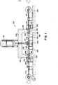
- the electrons are generated by an accelerator 112 of known construction.
- the cable 102 starts on a storage reel 120.
- the cable 102 passes through a pay-out device 122 from which the cable 102 enters a shielded compartment 124 which contains a first guidance and leakage prevention structure 126.
- the cable 102 passes through the first structure 125 and through a fixed length tube 128 which is coupled to the first structure 126.
- a sprocket 130 is also coupled to the tube 128 and the first structure 126 that is coaxial with the tube 128 and the first structure 126.
- Sprocket 130 is driven by a chain 180 from an external source to ensure that tube 128 rotates at the same speed as cable 102.
- the tube 128 extends through the aperture 106. Encircling the tube 128 along the aperture 106 is a cylinder 134 affixed to the wall 108.
- the cylinder 134 is coupled to a conventional bearing assembly 132 into which the tube 128 is rotatably mounted.
- the tube 128, which contains the cable 102, is supported by a stand 140 which is attached to the floor of the chamber 104. That is, the tube 128 is rotatably coupled, by bearings or the like, to the stand 140. The tube 128 extends into a second cable guidance and leakage prevention structure 142.
- the cable 102 exits the second structure 142, passes under the electron beam, and enters a third cable guidance and leakage prevention structure 150.
- the cable 102 then passes through another fixed length tube 152 which is rotatably coupled to a stand 154 and rotatably mounted in the aperture 107 by a bearing assembly 156.
- the stands 140 and 154 are close so that the catenary effect on the cable 102 as it rotates is greatly reduced.
- the tube 152 is encircled by a stationary cylinder 158. Outside the wall 109 and connected to the tube 152 is a fourth cable guidance and leakage prevention structure 160 in a shielded compartment 162.
- the fourth structure 160 and tube 152 are rotatably drivable by a sprocket 164 that cooperates with a driven chain (not shown in Figure 1).
- the cable 102 then enters a conventional take-up device 170 and take-up reel 172.
- the cable 102 has wire extending its length surrounded by insulation which is affected by electrons impinging thereon.
- the insulation may be relatively thick, it is noted. Because the cable 102 rotates under the beam, the beam is able to uniformly penetrate such insulation.
- wire, tubing, pipe or other such elements which can be paid out from and taken-up onto a reel may be equivalent substitutes for the cable being processed in the above discussion.
- FIG. 1 A further examination of Figure 1 shows rotation arrows by the reels 120 and 172.
- the reels 120 and 172 can be rotated about their respective axes which are coaxial with the general longitudinal axis of the cable 102 travelling through the chamber 104. In that way, the cable 102 is rotated about its axis as it travels longitudinally.
- the tubes 128 and 152 are rotated in synchrony with the rotation of the cable 102. Any insulation or outer skin on the cable 102 is thus engaged by the first structure 126, second structure 142, third structure 150 and fourth structure 160 which rotate in synchrony with the cable 102 about the axis of the cable 102. Zhus, the insulation or skin is not adversely affected due to the rotation.
- the purpose of rotating the cable 102 is, it is noted, to expose differing portions of the cable periphery to the electron beam over time.
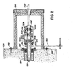
- the first structure 126 driven by sprocket 130 (and chain 180) are shown in detail, housed within shielded compartment 124.
- the compartment 124 is anchored to the wall 108 with bolts 182 or the like.
- the tube 128 is shown rotatably mounted with respect to the cylinder 134 by the bearing assembly 132'.
- the tube 128 extends into the first structure 126 as a tube length 128' (which is either an integral extension or an affixedly coupled extension of the tube 128).
- a cover 200 Surrounding the tube length 128' is a cover 200 which is comprised of a conventional shielding material.
- slits Disposed along the tube length 128' are slits, such as slits 202 through 208.
- Movable radially inward and outward through each slit, such as slit 202 through 208, relative to the cable 102 is a roller 210 through 216, respectively.
- the rollers 210 through 216 - which abut the cable 102 - also rotate about the cable axis.
- rollers 300 through 306 abut a cable 308 shown in cross-section.
- the cable 308 has a fairly large diameter.
- the rollers 300 through 306 are spring-loaded with mechanisms, such as mechanism 310, to engage the cable 308. Because of the spring-loading, the rollers 300 to 306 can, to some extent, accorrbdate cables 308 of varying diameters, smaller diameter cables having less engaging force applied thereto.
- an adjusting screw 316 is provided. In Figure 3, with the screw 316 turned to one axial position, the rollers 300 through 306 provide a corresponding opening therein.
- rollers 300, 400, 402 and 306 form a 90 P annular region about the cable 308 approximately equal to the diameter of each roller 300, 400, 402 and 306.
- an entire annular region is defined about the cable axis which substantially blocks the passage of longitudinal or other linear radiation therethrough. That is, by orienting roller 400 an angle of 30° offset from roller 300 and by angularly offsetting the roller 402 60° relative to roller 300, the straight-line paths of radiation through the annular space between rollers 300 and 306 are substantially reduced.
- the leakage paths would be even further reduced.
- Rollers 210 through 214 (and a fourth roller which is not visible) comprise a first set 500 of rollers.
- roller 216 To the right thereof in Figure 1 is roller 216 and three other rollers (not numbered) which comprise a second set 502. Spaced longitudinally to the right of the second set 502 is a third set of rollers 504.
- Each set 500 through 504 includes four rollers spaced at angular intervals about the cable axis, each roller in each set having an axis of rotation perpendicular to the cable axis.
- the rollers of each set 500 through 504 are spaced at equal angular intervals.
- the intervals are 90°.
- the rollers are all equal in dimensions. Still referring to Figure 1, it can be seen that the rollers of the first set 500 (210 through 214 for example) are angularly offset relative to the rollers of the second set 502 and the third set 504.
- rollers of the set 500 are considered positioned about the cable axis at the 0 0 , 90°, 180°, and 270° positions; the rollers of the third set are at positions 30°, 120°, 210°, and 300° while the rollers of the second set are at positions 60°, 150°, 240°, and 330°.
- rollers 300 through 306 may be considered in the first set of rollers with roller 400 being in the second set and roller 402 being in the third set. Also evident in Figure 3 is the fact that, with (a) rollers of a prescribed axial length, (b) a prescribed angular interval between rollers in each set, and (c) a prescribed offsetting of longitudinally spaced sets, a substantial reduction or elimination in leakage paths is achieved. In this regard, it is noted that by increasing the number of offset sets or by increasing the axial length of each roller, i.e. angle about the cable subtended by the roller, radiation blockage may be increased.
- a shield cover 602 (like cover 200 of Figure 1).
- each of the structures 126 and 160 are substantially similar in design. Structures 142 and 150 are also similar to structures 126 and 160, although there is an absence of a shield compartment and the structures 142 and 150 are within the chamber 104 whereas structures 126 and 160 are outside the chamber 104.
- the two structures 126 and 142 cooperate to reduce leakage. Additional structures of this kind disposed along the tube 128 would further enhance leakage reduction while also providing additional cable guidance. Specifically, with more structures and support stands, catenary effects resulting from cable rotation are diminished and cable rotation speeds of 50-200 rpm can be realized.
- Each structure 126, 142, 150 and 160 includes an arrangement of sets of rollers, the sets in each arrangement being spaced longitudinally apart - preferably at equal spacings - with the rollers in each set being disposed about the cable axis at angular intervals which, again, are preferably equal.
- the various sets of each arrangement are angularly offset, the offsetting being defined so that one roller from at least one set lies along a large number of linear paths extending through an annular region about the cable 102.
- the aperture sizes are as small as possible and the clearance between the cylinders 134 and 158 and the respective tubes 128 and 152 are minimized.
- the stands 140 and 154 are positioned proximate to where the beam intercepts the cable 102. Further a cooler 700 is provided under the beam.
- tubes, cylinders, covers, and chambers may be constructed of known shield-type materials.
Landscapes
- Physics & Mathematics (AREA)
- Engineering & Computer Science (AREA)
- General Engineering & Computer Science (AREA)
- High Energy & Nuclear Physics (AREA)
- Processes Specially Adapted For Manufacturing Cables (AREA)
- Radiation-Therapy Devices (AREA)
- Analysing Materials By The Use Of Radiation (AREA)
Applications Claiming Priority (2)
| Application Number | Priority Date | Filing Date | Title |
|---|---|---|---|
| US06/430,438 US4482811A (en) | 1982-09-30 | 1982-09-30 | Apparatus for guiding cable through a radiation chamber with reduced leakage therefrom |
| US430438 | 1995-04-28 |
Publications (2)
| Publication Number | Publication Date |
|---|---|
| EP0107280A2 true EP0107280A2 (de) | 1984-05-02 |
| EP0107280A3 EP0107280A3 (de) | 1985-08-21 |
Family
ID=23707568
Family Applications (1)
| Application Number | Title | Priority Date | Filing Date |
|---|---|---|---|
| EP83304580A Ceased EP0107280A3 (de) | 1982-09-30 | 1983-08-08 | Apparat zur Führung eines Kabels durch eine Strahlungskammer mit verminderter Leckage |
Country Status (3)
| Country | Link |
|---|---|
| US (1) | US4482811A (de) |
| EP (1) | EP0107280A3 (de) |
| CA (1) | CA1219973A (de) |
Cited By (1)
| Publication number | Priority date | Publication date | Assignee | Title |
|---|---|---|---|---|
| GB2157140A (en) * | 1984-03-23 | 1985-10-16 | Rpc Ind | Electron beam reaction chamber |
Families Citing this family (3)
| Publication number | Priority date | Publication date | Assignee | Title |
|---|---|---|---|---|
| JPS62250661A (ja) * | 1986-04-23 | 1987-10-31 | Fuji Electric Co Ltd | 半導体装置 |
| US4909864A (en) * | 1986-09-16 | 1990-03-20 | Kawasaki Steel Corp. | Method of producing extra-low iron loss grain oriented silicon steel sheets |
| JP2927284B2 (ja) * | 1997-12-22 | 1999-07-28 | 日本電気株式会社 | 磁気シールドルーム |
Family Cites Families (6)
| Publication number | Priority date | Publication date | Assignee | Title |
|---|---|---|---|---|
| GB1028148A (en) * | 1963-12-13 | 1966-05-04 | Standard Telephones Cables Ltd | The manufacture of an electric cable |
| US3482100A (en) * | 1966-02-21 | 1969-12-02 | Central Research Lab Inc | Labyrinth shielding for master-slave manipulator |
| US3499141A (en) * | 1967-11-13 | 1970-03-03 | High Voltage Engineering Corp | Self-shielded festoon for electron irradiation apparatus employing overlapping rollers having radiation blocking means |
| GB1353831A (en) * | 1970-07-15 | 1974-05-22 | Armco Steel Corp | Apparatus and process for radiation curing of coated strip-like material |
| GB2003009A (en) * | 1977-07-20 | 1979-02-28 | Akzona Inc | Process and apparatus for the radiation curing of cable insulation |
| JPS5914209B2 (ja) * | 1977-09-30 | 1984-04-03 | 日本原子力研究所 | 改良された絶縁体層を持つたゴムまたはプラスチツク絶縁電線またはケ−ブルの製造方法 |
-
1982
- 1982-09-30 US US06/430,438 patent/US4482811A/en not_active Expired - Fee Related
-
1983
- 1983-08-08 EP EP83304580A patent/EP0107280A3/de not_active Ceased
- 1983-09-23 CA CA000437502A patent/CA1219973A/en not_active Expired
Cited By (1)
| Publication number | Priority date | Publication date | Assignee | Title |
|---|---|---|---|---|
| GB2157140A (en) * | 1984-03-23 | 1985-10-16 | Rpc Ind | Electron beam reaction chamber |
Also Published As
| Publication number | Publication date |
|---|---|
| US4482811A (en) | 1984-11-13 |
| CA1219973A (en) | 1987-03-31 |
| EP0107280A3 (de) | 1985-08-21 |
Similar Documents
| Publication | Publication Date | Title |
|---|---|---|
| US3684887A (en) | Apparatus for inspecting tubular goods having an automatic shutter | |
| US4288700A (en) | Cable handling device for diagnostic x-ray apparatus | |
| US4366577A (en) | Computed tomography system cable retractor | |
| EP0107280A2 (de) | Apparat zur Führung eines Kabels durch eine Strahlungskammer mit verminderter Leckage | |
| US4397032A (en) | Cable guide, as well as medical apparatus provided with such a cable guide | |
| GB2038590A (en) | Apparatus for use in imaging a cross-section of a body | |
| JP4361759B2 (ja) | 二重スライス電子ビーム断層写真法スキャナ用のコリメーション・システム | |
| GB2212975A (en) | Rotating anode X-ray tube | |
| US4114043A (en) | Cable-supporting arrangement for x-ray tomographic scanner | |
| CN114947911B (zh) | 用于射线检查的成像系统 | |
| US20140048718A1 (en) | Charged particle beam irradiation apparatus | |
| US4093863A (en) | Tomographic apparatus | |
| KR20240097912A (ko) | 언더 빔 조사 장치 및 조사 가공 생산 라인 | |
| JP3590963B2 (ja) | 電子線照射装置 | |
| US6220752B1 (en) | X-ray examination apparatus | |
| US3661335A (en) | Anti-ricochet wire guard | |
| EP0004788A1 (de) | Apparat zur Bestrahlung einer langgestreckten Fläche | |
| US3322950A (en) | Linear accelerator radiotherapy device and associated beam defining structure | |
| JPS5931301B2 (ja) | 円形発電機界磁巻線を形成する方法及び装置 | |
| US3610498A (en) | Combination centrifugal guide and chain guide | |
| US4356846A (en) | Apparatus for stranding multi-layer cable | |
| JP7739121B2 (ja) | 回転ガントリーの冷却材供給装置および粒子線治療システム | |
| CA1214887A (en) | Radiation scanning and measuring device | |
| US4206362A (en) | Medical radiographic apparatus | |
| US3499141A (en) | Self-shielded festoon for electron irradiation apparatus employing overlapping rollers having radiation blocking means |
Legal Events
| Date | Code | Title | Description |
|---|---|---|---|
| PUAI | Public reference made under article 153(3) epc to a published international application that has entered the european phase |
Free format text: ORIGINAL CODE: 0009012 |
|
| AK | Designated contracting states |
Designated state(s): BE CH DE FR GB IT LI NL SE |
|
| 17P | Request for examination filed |
Effective date: 19841029 |
|
| PUAL | Search report despatched |
Free format text: ORIGINAL CODE: 0009013 |
|
| AK | Designated contracting states |
Designated state(s): BE CH DE FR GB IT LI NL SE |
|
| 17Q | First examination report despatched |
Effective date: 19870810 |
|
| STAA | Information on the status of an ep patent application or granted ep patent |
Free format text: STATUS: THE APPLICATION HAS BEEN REFUSED |
|
| 18R | Application refused |
Effective date: 19890508 |
|
| RIN1 | Information on inventor provided before grant (corrected) |
Inventor name: BURGESS, ROBERT G. |