EP0107251B1 - Vorrichtung zum automatischen Anbringen von Giessstutzen an Flüssigkeitsbehältern - Google Patents
Vorrichtung zum automatischen Anbringen von Giessstutzen an Flüssigkeitsbehältern Download PDFInfo
- Publication number
- EP0107251B1 EP0107251B1 EP83201483A EP83201483A EP0107251B1 EP 0107251 B1 EP0107251 B1 EP 0107251B1 EP 83201483 A EP83201483 A EP 83201483A EP 83201483 A EP83201483 A EP 83201483A EP 0107251 B1 EP0107251 B1 EP 0107251B1
- Authority
- EP
- European Patent Office
- Prior art keywords
- arm
- mouth
- seat
- movable
- container
- Prior art date
- Legal status (The legal status is an assumption and is not a legal conclusion. Google has not performed a legal analysis and makes no representation as to the accuracy of the status listed.)
- Expired
Links
- 238000004806 packaging method and process Methods 0.000 title claims abstract description 10
- 239000002184 metal Substances 0.000 title claims abstract description 9
- 239000012530 fluid Substances 0.000 title abstract 2
- 230000005484 gravity Effects 0.000 claims abstract description 3
- 238000009527 percussion Methods 0.000 claims description 6
- 230000009969 flowable effect Effects 0.000 claims description 3
- 230000000295 complement effect Effects 0.000 claims description 2
- 230000010355 oscillation Effects 0.000 description 2
- 230000037431 insertion Effects 0.000 description 1
- 238000003780 insertion Methods 0.000 description 1
- 239000000843 powder Substances 0.000 description 1
Images

Classifications
-
- B—PERFORMING OPERATIONS; TRANSPORTING
- B31—MAKING ARTICLES OF PAPER, CARDBOARD OR MATERIAL WORKED IN A MANNER ANALOGOUS TO PAPER; WORKING PAPER, CARDBOARD OR MATERIAL WORKED IN A MANNER ANALOGOUS TO PAPER
- B31B—MAKING CONTAINERS OF PAPER, CARDBOARD OR MATERIAL WORKED IN A MANNER ANALOGOUS TO PAPER
- B31B50/00—Making rigid or semi-rigid containers, e.g. boxes or cartons
- B31B50/74—Auxiliary operations
- B31B50/81—Forming or attaching accessories, e.g. opening devices, closures or tear strings
- B31B50/84—Forming or attaching means for filling or dispensing contents, e.g. valves or spouts
Definitions
- This invention relates to a device for automatically forming and applying metal delivery mouths to packaging containers for flowable products, in particular cardboard containers for powders.
- a device of this type is described for example in Italian patent 828,966.
- the delivery mouths are formed from a metal strip and fed intermittently to a device, the purpose of which is to apply them to the boxes.
- Said applicator device is formed structurally from a hammer and an anvil.
- the hammer comprises a cavity for receiving the formed delivery mouth, and is arranged to be moved, in synchronism with the anvil, into a position corresponding with the container in order to carry out the application of said mouth.
- Machines of the type described in Italian patent 828,966 are large rotary machines of high productivity, and comprise a turntable carrying a plurality of said applicator devices each cable of successively applying the delivery mouths to the containers, which are continuously fed in an upright position by a suitable conveyor.
- a machine of lower productivity able to be coupled to packaging machines into which the empty containers are conveyed in a lying position by spindles which move stepwise.
- the object of the present invention is to satisfy the aforesaid need, and for this purpose the invention provides a device for automatically forming and applying metal delivery mouths to packaging containers for flowable products, of the type in which each mouth is formed from a metal strip by a forming unit and is fed to a complementary seat in an arm provided with a hammer which is arranged to apply the mouth to a respective container, characterised in that said arm is movable alternately between a vertical position in which the mouth is received in said seat from said forming unit by gravity, and a horizontal position in which said mouth is applied to a container, there being provided a positioning unit arranged to correctly locate the mouth in the seat, and sequential operating means for said unit and said arm.
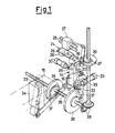
- the device according to the invention is formed from a frame 10 carrying a forming unit indicated diagrammatically by 11 and of known type, arranged to form delivery mouths 12 from a metal strip 13.
- the formed mouths 12 are fed one at a time to an underlying applicator device, indicated generally by 14, which offers them up to a cardboard container 15 and applies them thereto.
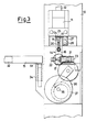
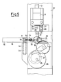
- the applicator device 14 comprises an L-shaped arm 16 which swivels about 17 between the vertical position shown in Figure 3 and the horizontal position shown in Figure 5.
- a percussion head 19 commonly known as a hammer, slides on suitable guides 18.
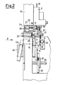
- said head 19 is articulated to one end of a bell crank lever 20 pivoted at 21 to the arm 16, and maintained in the position of Figure 2 by a spring 8.
- Said bell crank lever is oscillated by the rod 22 of a cylinder 23 fixed to the machine frame.
- a positioning unit indicated generally by 24 cooperates with the described applicator device 14.
- Said unit 24 is composed of a blade 25 and a pusher 26 which are rigid with each other and are carried by a slide 27 slidable on guides 28.
- a locking device also cooperates with the applicator device, and consists of the rod 29 of a cylinder 30, said rod becoming inserted into two bores 31 of the arm 16, so as to lock it exactly and securely in said vertical and horizontal positions.
- the containers 15 are mounted in a -lying position on spindles 32 of a packaging machine (not shown) movable stepwise.
- said spindles 32 carry each container 15 against a counter-member 33 which is movable vertically in a guide block 34 between the lowered position of Figure 3 and the raised position of Figure 5.
- the oscillation of the arm 16 about 17, the horizontal movement of the positioning unit 24 and the vertical movement of the counter-member 33 are controlled in the correct sequence by means of a single control system.
- This control system can for example comprise a drive shaft 35 with which there are rigid two plates 36 in which cam seats 37 are formed in order to provide, by means of lever systems, the abutting movement of the counter-member 33 and the oscillation of the arm 16 about 17 respectively.
- said shaft 35 drives a second shaft 39 carrying a third plate 36 comprising a cam seat 37 which operates the positioning unit 24 by means of lever systems.
- the delivery mouths 12, formed by the forming unit 11, are made to fall one at a time into the underlying applicator device 14. More specifically, the mouth 12 falls into the cavity 9 ( Figure 2) when the percussion head 19 is in its rest position, in which it is maintained by the action of the spring 8 on the bell crank lever 20.
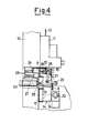
- the positioning unit 24 operated by the combination of the plate 36 with cam seat 37 driven by the shaft 39 and the respective lever systems, moves by virtue of the sliding of the slide 27 on the guides 28 until the blade 25 and the pusher 26, which is provided with elastic means, correctly position the mouth 12 against the percussion head 29 ( Figure 4).
- the cylinder 23 is operated so that its rod 22 engages against the lever 20 pivoted at 21, to cause the percussion head 19 to slide on the guides 18.
- the counter-member 33 is lowered inside the guide block 34, and the packaging machine rotates its spindle 32, which carries the container 15 to which the mouth 12 has been applied.
- the rod 29 of the cylinder 30 withdraws from the second bore 31 and enables the arm 16 to return to the vertical position under the forming unit 11, where it is locked by the engagement of the rod 29 of the cylinder 30 in the first bore 31 ( Figure 2).
Landscapes
- Auxiliary Devices For And Details Of Packaging Control (AREA)
- Basic Packing Technique (AREA)
- Making Paper Articles (AREA)
Claims (8)
Priority Applications (1)
| Application Number | Priority Date | Filing Date | Title |
|---|---|---|---|
| AT83201483T ATE28823T1 (de) | 1982-10-22 | 1983-10-18 | Vorrichtung zum automatischen anbringen von giessstutzen an fluessigkeitsbehaeltern. |
Applications Claiming Priority (2)
| Application Number | Priority Date | Filing Date | Title |
|---|---|---|---|
| IT23882/82A IT1152941B (it) | 1982-10-22 | 1982-10-22 | Dispositivo per applicare automaticamente bocche di erogazione metalliche a contenitori destinati alla confezione di prodotti a comportamento fluido |
| IT2388282 | 1982-10-22 |
Publications (3)
| Publication Number | Publication Date |
|---|---|
| EP0107251A2 EP0107251A2 (de) | 1984-05-02 |
| EP0107251A3 EP0107251A3 (en) | 1985-10-23 |
| EP0107251B1 true EP0107251B1 (de) | 1987-08-12 |
Family
ID=11210618
Family Applications (1)
| Application Number | Title | Priority Date | Filing Date |
|---|---|---|---|
| EP83201483A Expired EP0107251B1 (de) | 1982-10-22 | 1983-10-18 | Vorrichtung zum automatischen Anbringen von Giessstutzen an Flüssigkeitsbehältern |
Country Status (4)
| Country | Link |
|---|---|
| EP (1) | EP0107251B1 (de) |
| AT (1) | ATE28823T1 (de) |
| DE (1) | DE3372943D1 (de) |
| IT (1) | IT1152941B (de) |
Family Cites Families (5)
| Publication number | Priority date | Publication date | Assignee | Title |
|---|---|---|---|---|
| US2589769A (en) * | 1946-08-16 | 1952-03-18 | Seal Spout Corp | Machine for inserting pouring spouts into containers |
| US3025813A (en) * | 1959-12-14 | 1962-03-20 | Seal Spout Corp | Spout inserting machine |
| US3385248A (en) * | 1966-02-21 | 1968-05-28 | Seal Spout Corp | Machine for attaching spouts to containers |
| US3673663A (en) * | 1970-12-11 | 1972-07-04 | Seal Spout Europ Spa | Machine for applying pouring spouts to containers |
| DE3025118A1 (de) * | 1980-07-03 | 1982-01-28 | Robert Bosch Gmbh, 7000 Stuttgart | Vorrichtung zum anbringen von ventilen an packmitteln |
-
1982
- 1982-10-22 IT IT23882/82A patent/IT1152941B/it active
-
1983
- 1983-10-18 EP EP83201483A patent/EP0107251B1/de not_active Expired
- 1983-10-18 DE DE8383201483T patent/DE3372943D1/de not_active Expired
- 1983-10-18 AT AT83201483T patent/ATE28823T1/de not_active IP Right Cessation
Also Published As
| Publication number | Publication date |
|---|---|
| IT1152941B (it) | 1987-01-14 |
| EP0107251A3 (en) | 1985-10-23 |
| DE3372943D1 (en) | 1987-09-17 |
| IT8223882A0 (it) | 1982-10-22 |
| ATE28823T1 (de) | 1987-08-15 |
| EP0107251A2 (de) | 1984-05-02 |
Similar Documents
| Publication | Publication Date | Title |
|---|---|---|
| US3941037A (en) | Case forming and transferring machine | |
| US20030232709A1 (en) | Method and machine for gripping and opening punched cardboard elements and forming open-topped boxes | |
| AU668263B2 (en) | Collating apparatus | |
| US3640050A (en) | Bag-boxing machine | |
| GB1293659A (en) | A cigarette packaging machine | |
| US3386224A (en) | Case packer | |
| US4023513A (en) | Method and apparatus for transferring cans | |
| EP0734949A1 (de) | Vorrichtung zum Bilden von Gruppen von Gegenständen in Kartoniermaschinen oder dergleichen | |
| EP0107251B1 (de) | Vorrichtung zum automatischen Anbringen von Giessstutzen an Flüssigkeitsbehältern | |
| US3903672A (en) | Method and machine for filled bag production | |
| GB1388005A (en) | Packing machines | |
| US3197816A (en) | Machine for the manufacture of deepdrawn hollow articles from thermoplastic synthetic material | |
| US2589769A (en) | Machine for inserting pouring spouts into containers | |
| US2652963A (en) | Automatic bottle sealing | |
| EP0798263A1 (de) | Behälterverschliess-und Füllvorrichtung | |
| US4269298A (en) | Tray indexing apparatus | |
| US3025813A (en) | Spout inserting machine | |
| US3086428A (en) | Box-wrapping system for loosewrap work | |
| US3388527A (en) | Case filling machine | |
| EP0454472B1 (de) | Vorrichtung zum Anbringen von Identifizierungsabschnitten an Flaschenkästen | |
| US3574986A (en) | Apparatus for vertically loading cartons | |
| US3793872A (en) | Forging press feed mechanism | |
| US2344460A (en) | Machine for assembling metal containers | |
| EP0825111A1 (de) | Maschine zum Formen von Pappschachteln | |
| US3699744A (en) | Carton closing apparatus |
Legal Events
| Date | Code | Title | Description |
|---|---|---|---|
| PUAI | Public reference made under article 153(3) epc to a published international application that has entered the european phase |
Free format text: ORIGINAL CODE: 0009012 |
|
| AK | Designated contracting states |
Designated state(s): AT BE CH DE FR GB LI LU NL SE |
|
| PUAL | Search report despatched |
Free format text: ORIGINAL CODE: 0009013 |
|
| AK | Designated contracting states |
Designated state(s): AT BE CH DE FR GB LI LU NL SE |
|
| 17P | Request for examination filed |
Effective date: 19860403 |
|
| 17Q | First examination report despatched |
Effective date: 19860906 |
|
| R17C | First examination report despatched (corrected) |
Effective date: 19860908 |
|
| GRAA | (expected) grant |
Free format text: ORIGINAL CODE: 0009210 |
|
| AK | Designated contracting states |
Kind code of ref document: B1 Designated state(s): AT BE CH DE FR GB LI LU NL SE |
|
| REF | Corresponds to: |
Ref document number: 28823 Country of ref document: AT Date of ref document: 19870815 Kind code of ref document: T |
|
| REF | Corresponds to: |
Ref document number: 3372943 Country of ref document: DE Date of ref document: 19870917 |
|
| ET | Fr: translation filed | ||
| PLBE | No opposition filed within time limit |
Free format text: ORIGINAL CODE: 0009261 |
|
| STAA | Information on the status of an ep patent application or granted ep patent |
Free format text: STATUS: NO OPPOSITION FILED WITHIN TIME LIMIT |
|
| 26N | No opposition filed | ||
| EPTA | Lu: last paid annual fee | ||
| EAL | Se: european patent in force in sweden |
Ref document number: 83201483.1 |
|
| REG | Reference to a national code |
Ref country code: GB Ref legal event code: IF02 |
|
| PGFP | Annual fee paid to national office [announced via postgrant information from national office to epo] |
Ref country code: SE Payment date: 20021004 Year of fee payment: 20 |
|
| PGFP | Annual fee paid to national office [announced via postgrant information from national office to epo] |
Ref country code: FR Payment date: 20021008 Year of fee payment: 20 |
|
| PGFP | Annual fee paid to national office [announced via postgrant information from national office to epo] |
Ref country code: AT Payment date: 20021011 Year of fee payment: 20 |
|
| PGFP | Annual fee paid to national office [announced via postgrant information from national office to epo] |
Ref country code: GB Payment date: 20021016 Year of fee payment: 20 |
|
| PGFP | Annual fee paid to national office [announced via postgrant information from national office to epo] |
Ref country code: DE Payment date: 20021024 Year of fee payment: 20 |
|
| PGFP | Annual fee paid to national office [announced via postgrant information from national office to epo] |
Ref country code: LU Payment date: 20021029 Year of fee payment: 20 |
|
| PGFP | Annual fee paid to national office [announced via postgrant information from national office to epo] |
Ref country code: NL Payment date: 20021031 Year of fee payment: 20 |
|
| PGFP | Annual fee paid to national office [announced via postgrant information from national office to epo] |
Ref country code: CH Payment date: 20021101 Year of fee payment: 20 |
|
| PGFP | Annual fee paid to national office [announced via postgrant information from national office to epo] |
Ref country code: BE Payment date: 20021219 Year of fee payment: 20 |
|
| PG25 | Lapsed in a contracting state [announced via postgrant information from national office to epo] |
Ref country code: LI Free format text: LAPSE BECAUSE OF EXPIRATION OF PROTECTION Effective date: 20031017 Ref country code: GB Free format text: LAPSE BECAUSE OF EXPIRATION OF PROTECTION Effective date: 20031017 Ref country code: CH Free format text: LAPSE BECAUSE OF EXPIRATION OF PROTECTION Effective date: 20031017 |
|
| PG25 | Lapsed in a contracting state [announced via postgrant information from national office to epo] |
Ref country code: NL Free format text: LAPSE BECAUSE OF EXPIRATION OF PROTECTION Effective date: 20031018 Ref country code: LU Free format text: LAPSE BECAUSE OF EXPIRATION OF PROTECTION Effective date: 20031018 Ref country code: AT Free format text: LAPSE BECAUSE OF EXPIRATION OF PROTECTION Effective date: 20031018 |
|
| BE20 | Be: patent expired |
Owner name: *SEAL SPOUT INTERNATIONAL Effective date: 20031018 |
|
| REG | Reference to a national code |
Ref country code: GB Ref legal event code: PE20 |
|
| REG | Reference to a national code |
Ref country code: CH Ref legal event code: PL |
|
| NLV7 | Nl: ceased due to reaching the maximum lifetime of a patent |
Effective date: 20031018 |
|
| EUG | Se: european patent has lapsed |