EP0107151B1 - Door closer control arm - Google Patents
Door closer control arm Download PDFInfo
- Publication number
- EP0107151B1 EP0107151B1 EP83110197A EP83110197A EP0107151B1 EP 0107151 B1 EP0107151 B1 EP 0107151B1 EP 83110197 A EP83110197 A EP 83110197A EP 83110197 A EP83110197 A EP 83110197A EP 0107151 B1 EP0107151 B1 EP 0107151B1
- Authority
- EP
- European Patent Office
- Prior art keywords
- rod
- door closer
- toothing
- locking piece
- mounting rod
- Prior art date
- Legal status (The legal status is an assumption and is not a legal conclusion. Google has not performed a legal analysis and makes no representation as to the accuracy of the status listed.)
- Expired
Links
Images


Classifications
-
- E—FIXED CONSTRUCTIONS
- E05—LOCKS; KEYS; WINDOW OR DOOR FITTINGS; SAFES
- E05F—DEVICES FOR MOVING WINGS INTO OPEN OR CLOSED POSITION; CHECKS FOR WINGS; WING FITTINGS NOT OTHERWISE PROVIDED FOR, CONCERNED WITH THE FUNCTIONING OF THE WING
- E05F3/00—Closers or openers with braking devices, e.g. checks; Construction of pneumatic or liquid braking devices
-
- E—FIXED CONSTRUCTIONS
- E05—LOCKS; KEYS; WINDOW OR DOOR FITTINGS; SAFES
- E05Y—INDEXING SCHEME RELATING TO HINGES OR OTHER SUSPENSION DEVICES FOR DOORS, WINDOWS OR WINGS AND DEVICES FOR MOVING WINGS INTO OPEN OR CLOSED POSITION, CHECKS FOR WINGS AND WING FITTINGS NOT OTHERWISE PROVIDED FOR, CONCERNED WITH THE FUNCTIONING OF THE WING
- E05Y2201/00—Constructional elements; Accessories therefore
- E05Y2201/60—Suspension or transmission members; Accessories therefore
- E05Y2201/622—Suspension or transmission members elements
- E05Y2201/624—Arms
-
- E—FIXED CONSTRUCTIONS
- E05—LOCKS; KEYS; WINDOW OR DOOR FITTINGS; SAFES
- E05Y—INDEXING SCHEME RELATING TO HINGES OR OTHER SUSPENSION DEVICES FOR DOORS, WINDOWS OR WINGS AND DEVICES FOR MOVING WINGS INTO OPEN OR CLOSED POSITION, CHECKS FOR WINGS AND WING FITTINGS NOT OTHERWISE PROVIDED FOR, CONCERNED WITH THE FUNCTIONING OF THE WING
- E05Y2800/00—Details, accessories and auxiliary operations not otherwise provided for
- E05Y2800/37—Length, width adjustment
-
- E—FIXED CONSTRUCTIONS
- E05—LOCKS; KEYS; WINDOW OR DOOR FITTINGS; SAFES
- E05Y—INDEXING SCHEME RELATING TO HINGES OR OTHER SUSPENSION DEVICES FOR DOORS, WINDOWS OR WINGS AND DEVICES FOR MOVING WINGS INTO OPEN OR CLOSED POSITION, CHECKS FOR WINGS AND WING FITTINGS NOT OTHERWISE PROVIDED FOR, CONCERNED WITH THE FUNCTIONING OF THE WING
- E05Y2900/00—Application of doors, windows, wings or fittings thereof
- E05Y2900/10—Application of doors, windows, wings or fittings thereof for buildings or parts thereof
- E05Y2900/13—Application of doors, windows, wings or fittings thereof for buildings or parts thereof characterised by the type of wing
- E05Y2900/132—Doors
-
- Y—GENERAL TAGGING OF NEW TECHNOLOGICAL DEVELOPMENTS; GENERAL TAGGING OF CROSS-SECTIONAL TECHNOLOGIES SPANNING OVER SEVERAL SECTIONS OF THE IPC; TECHNICAL SUBJECTS COVERED BY FORMER USPC CROSS-REFERENCE ART COLLECTIONS [XRACs] AND DIGESTS
- Y10—TECHNICAL SUBJECTS COVERED BY FORMER USPC
- Y10S—TECHNICAL SUBJECTS COVERED BY FORMER USPC CROSS-REFERENCE ART COLLECTIONS [XRACs] AND DIGESTS
- Y10S16/00—Miscellaneous hardware, e.g. bushing, carpet fastener, caster, door closer, panel hanger, attachable or adjunct handle, hinge, window sash balance
- Y10S16/39—Adjustment means
-
- Y—GENERAL TAGGING OF NEW TECHNOLOGICAL DEVELOPMENTS; GENERAL TAGGING OF CROSS-SECTIONAL TECHNOLOGIES SPANNING OVER SEVERAL SECTIONS OF THE IPC; TECHNICAL SUBJECTS COVERED BY FORMER USPC CROSS-REFERENCE ART COLLECTIONS [XRACs] AND DIGESTS
- Y10—TECHNICAL SUBJECTS COVERED BY FORMER USPC
- Y10T—TECHNICAL SUBJECTS COVERED BY FORMER US CLASSIFICATION
- Y10T403/00—Joints and connections
- Y10T403/32—Articulated members
- Y10T403/32254—Lockable at fixed position
- Y10T403/32426—Plural distinct positions
Definitions
- the invention relates to a door closer linkage for the connection between the closer shaft of an overhead door closer and the door leaf or door frame, with a main arm and an adjustment arm connected to it in an articulated manner, which comprises a receiving rod and an adjusting rod which is connected to it in an adjustable manner and which is guided telescopically in the receiving rod, wherein the actuating rod and the receiving rod can be connected to one another by a releasable locking piece using a safety element.
- Door closer linkage can be adjusted in a wide range in order to be able to be adapted to the respective door situation, such as different lintel depth, connection point shift due to different door widths, etc.
- a door closer linkage is known from DE-A 2006069, the adjusting arm of which is formed from a receiving rod and an adjusting rod.
- the tubular receiving rod has clamping fingers formed by slots which can be pressed against a roughened surface of the adjusting rod by a union nut.
- the mounting rod and the actuating rod are thus connected to one another only by frictional engagement, so that it is doubtful whether the connection point is able to withstand the constant load intervals in the long term.
- a tubular receiving rod and an adjusting rod inserted therein can be telescopically displaced relative to one another, the receiving rod having an elongated hole and being connected to the adjusting rod in a selectable position by a screw held therein.
- the disadvantage of this embodiment is the material-weakening elongated hole, and it is also doubtful whether a clamping screw that creates only a non-positive connection secures the setting position, particularly in the case of high, intermittent closing forces.
- the object of the present invention is to provide a door closer linkage which, without dismantling the connection point, can be adjusted quickly and, if necessary, also over large length ranges in a simple manner without great expenditure on components, and which are secured in the set position by a positive connection.
- the actuating rod has a toothing on one longitudinal side of its shaft which corresponds to a toothing on at least one side wall of a section of the receiving rod encompassing the actuating rod and the locking piece engaging in the toothing with a toothing is arranged in the cutout of the receiving rod is.
- the locking piece is comprised of a sliding tube which can be fixed on the articulated head of the actuating rod and which overlaps the actuating rod and the receiving rod and forms the securing member.
- the sliding tube is preferably formed at its end facing the joint head of the actuating rod by two slots as a resilient tongue and provided within the tongue with an inward-pointing projection which can be snapped into a recess in the joint head of the actuating rod.
- Such a sliding tube covering the receiving rod and the actuating rod prevents a release of the form-fitting connection of the actuating rod and the receiving rod in its securing position, since the locking piece is held in its connecting position and also gives the adjusting arm a pleasing, compact appearance.
- the adjustment arm and the support rod of the door closer linkage can be formed from components with a round cross-section, it is advantageous for connecting the adjustment arm to a connecting joint for attachment to the door frame or to the door leaf and to form a joint head that can be connected to the main arm, if, as proposed according to a further embodiment of the invention, the receiving rod is designed as a tube with a rectangular cross-section and at its end opposite the connecting joint has a cutout formed by cutting a narrow side, in the area of which both longitudinal walls are provided with a corresponding toothing, and the locking piece with the narrow side of the receiving rod has the same width over which one matches the toothing of the adjusting rod and the receiving rod extending toothing extends.
- the locking piece advantageously has a swivel bead following its toothing, which is articulated in recesses in the longitudinal walls in the region of the cutout of the receiving rod intervenes.
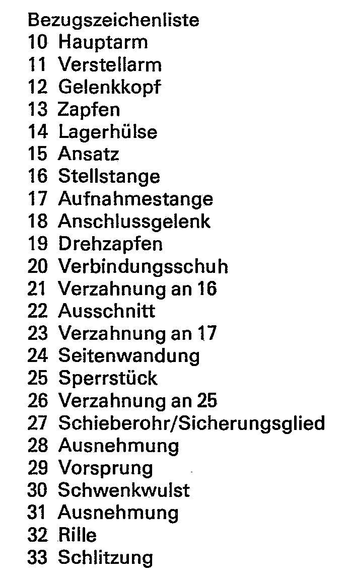
- the door closer linkage comprises a main arm 10 and an adjusting arm 11, which are pivotally connected to one another via a joint head 12 located on the adjusting arm and a pin 13 located on the main arm with the interposition of a bearing sleeve 14.
- the joint head 12 is part of an actuating rod 15 which, following the joint head 12, has a shoulder 15 with a rectangular cross section, to which an adjusting rod 16 is connected, which - as can be seen in particular from FIG. 3 - has a double-T-shaped cross section having.
- This adjusting rod 16 is finally encompassed by a rectangular tubular receiving rod 17, which is fork-shaped at one end and is movably connected to a connecting joint 18 via a pivot pin 19.
- a connecting shoe 20 is pivotally mounted on the connection joint 18 and can be screwed to a door leaf or a door frame, for example.
- the adjusting rod 16 On a narrow side, the adjusting rod 16 has teeth 21 along its entire length.
- the rectangular tubular receiving rod 17 has on one of its two narrow sides a cutout 22 which extends in the longitudinal direction in some areas, the longitudinally extending contour of which is designed as toothing 23 on both side walls 24 of the receiving rod 17.
- the toothings 21 and 23 are identical in shape and dimensions, so that with the corresponding longitudinal position of the adjusting rod 16 relative to the receiving rod 17, these toothings can be placed congruently next to one another.
- an essentially corresponding to the wall thickness of the cutout locking piece 25 is embedded, which is also provided on its side facing the actuating rod 16 and the side walls 24 of the receiving rod 17 with a toothing 26 which is in shape and dimensions with the toothing 21 and 23 match.
- the width of the locking piece 25 corresponds to the width of the receiving rod 17 comprising the actuating rod 16, so that in the engaged position the locking piece 25 engages with its toothing 26 in the toothing 21 of the adjusting rod 16 and the toothing 23 in the side walls 24 of the receiving rod 17.
- the adjusting rod 16 is fixed relative to the receiving rod 17 and the distance between the joint head 12 and the connecting shoe 20 is adjusted.
- the receiving rod 17 is enclosed by a sliding tube 27 which holds the locking piece 25 in the connecting position with the adjusting rod 16 and the receiving rod 17.
- the sliding tube 27 is somewhat shorter than the distance between the connecting shoe 20 and the joint head 12 in the pushed-together state of the adjusting rod 16 and the receiving rod 17 in order to be able to push the sliding tube 27 back so far that the connection position between the locking piece 25 and actuating rod 16 and receiving rod 17 can be removed.
- a recess 28 is arranged on the extension 15 of the actuating rod 16 on two mutually opposite sides, into which the projection 29, which is resiliently formed on the slide tube 27 by slots 33, can snap into place.
- the sliding tube 27 fulfills the function of a securing member.
- the blocking piece 25 In order to hold the blocking piece 25 on the adjusting arm 11 during the adjustment of the adjusting rod 16 and the receiving rod 17, the blocking piece 25 has a swivel bead 30 following its toothing 26. This swivel bead engages in semicircular recesses 31 in the side walls 24 of the receiving rod 17. To release the locking piece 25 from a locking connection, the sliding tube 27 is only pushed back so far that the locking piece 25 can be pivoted out of the teeth, but the sliding tube 27 in the area of the swivel bead 30 still remains over the locking piece 25. So that the pivoting movement of the locking piece is made possible, a groove 32 which enables the pivoting is provided on the outside of the locking piece in the region of its pivoting bead 30.
- the sliding tube 27 acting as a securing member is first released from its latching connection 28, 29 and pushed back so far from the joint head 12 that the locking piece can swing out of its engagement position and only remains with its swivel bead 30 in the recess 31.
- the control rod 16, which is designed as a toothed rack, can now be pushed in or out as far as desired and can be positively connected to the tubular receiving rod 17 again in the desired length setting of the adjusting arm 11.
- the sliding tube is then pushed back towards the joint head 12 until it engages over its shoulder 15 and engages with its projections 29 in the recess 28 of the shoulder 15.
- the set position between the adjusting rod 16 and the receiving rod 17 is thus secured and the entire adjusting unit is covered, so that the exterior of the adjusting arm 11 is pleasing.
Description
Die Erfindung bezieht sich auf ein Türschliessergestänge zur Verbindung zwischen der Schliesserwelle eines Obentürschliessers und dem Türflügel oder Türrahmen, mit einem Hauptarm und einem damit gelenkig verbundenen Verstellarm, der eine Aufnahmestange und eine damit verstellbar verbundene Stellstange umfasst, die teleskopartig in der Aufnahmestange verschiebbar geführt ist, wobei Stellstange und Aufnahmestange durch ein lösbares Sperrstück miteinander unter Verwendung eines Sicherheitsgliedes verbindbar sind.The invention relates to a door closer linkage for the connection between the closer shaft of an overhead door closer and the door leaf or door frame, with a main arm and an adjustment arm connected to it in an articulated manner, which comprises a receiving rod and an adjusting rod which is connected to it in an adjustable manner and which is guided telescopically in the receiving rod, wherein the actuating rod and the receiving rod can be connected to one another by a releasable locking piece using a safety element.
Türschliessergestänge sind in weiten Bereichen verstellbar, um an die jeweilige Türsituation, wie beispielsweise unterschiedliche Sturztiefe, Anschlusspunktverlagerung infolge verschiedener Türbreiten usw., angepasst werden zu können.Door closer linkage can be adjusted in a wide range in order to be able to be adapted to the respective door situation, such as different lintel depth, connection point shift due to different door widths, etc.
Zur Verstellung von Türschliessergestängen ist es, z.B. aus der DE-C 289153 bekannt, den Verstellarm aus einer ein Innengewinde aufweisenden Aufnahmestange und aus einer in diese mit einem Aussengewinde einschraubbaren Stellstange zu bilden. Um einen derartigen Verstellarm in seiner Länge einzustellen, ist es erforderlich, das Türschliessergestänge vor Ort mit seinem Anlenkstück vom Türflügel bzw. Türrahmen zu trennen, um danach in einer mehr oder weniger langwierigen Operation die Stellstange aus der Aufnahmestange heraus- oder in die Aufnahmestangen hineinzuschrauben.To adjust the door closer linkage, e.g. known from DE-C 289153 to form the adjusting arm from a receiving rod having an internal thread and from an adjusting rod which can be screwed into it with an external thread. In order to adjust the length of such an adjustment arm, it is necessary to separate the door closer linkage on-site with its link from the door leaf or door frame, in order to then unscrew the adjusting rod from the receiving rod or into the receiving rods in a more or less lengthy operation.
Aus der DE-A 2006069 ist ein Türschliessergestänge bekannt, dessen Verstellarm aus einer Aufnahmestange und einer Verstellstange gebildet ist. Dabei weist die rohrförmige Aufnahmestange durch Schlitze gebildete Klemmfinger auf, die durch eine Überwurfmutter gegen eine aufgerauhte Fläche der Stellstange anpressbar sind. Die Aufnahmestange und die Stellstange sind somit nur durch Reibschluss miteinander verbunden, so dass zu bezweifeln ist, ob die Verbindungsstelle dauerhaft den ständigen Belastungsintervallen gewachsen ist.A door closer linkage is known from DE-A 2006069, the adjusting arm of which is formed from a receiving rod and an adjusting rod. The tubular receiving rod has clamping fingers formed by slots which can be pressed against a roughened surface of the adjusting rod by a union nut. The mounting rod and the actuating rod are thus connected to one another only by frictional engagement, so that it is doubtful whether the connection point is able to withstand the constant load intervals in the long term.
Bei einem aus der FR-A 2378163 bekannten Türschliessergestänge lassen sich eine rohrförmige Aufnahmestange und eine darin eingeführte Stellstange gegeneinander teleskopartig verschieben, wobei die Aufnahmestange ein Langloch aufweist und mit der Stellstange durch eine in dieser gehalterte Schraube in auswählbaren Lagen verbunden ist. Nachteilig ist bei dieser Ausführung das materialschwächende Langloch, und es ist ausserdem zweifelhaft, ob eine nur eine kraftschlüssige Verbindung schaffende Klemmschraube die Einstellage, insbesondere bei hohen, intervallartig auftretenden Schliesskräften in ausreichender Weise sichert.In a door closer linkage known from FR-A 2378163, a tubular receiving rod and an adjusting rod inserted therein can be telescopically displaced relative to one another, the receiving rod having an elongated hole and being connected to the adjusting rod in a selectable position by a screw held therein. The disadvantage of this embodiment is the material-weakening elongated hole, and it is also doubtful whether a clamping screw that creates only a non-positive connection secures the setting position, particularly in the case of high, intermittent closing forces.
Die Aufgabe der vorliegenden Erfindung besteht darin, ein Türschliessergestänge zu schaffen, das ohne Demontage der Verbindungsstelle schnell und bedarfsweise auch über grosse Längenbereiche auf einfache Weise ohne grossen Bauteileaufwand einerseits verstellbar ist und andererseits durch eine Formschlussverbindung in der eingestellten Lage gesichert sind.The object of the present invention is to provide a door closer linkage which, without dismantling the connection point, can be adjusted quickly and, if necessary, also over large length ranges in a simple manner without great expenditure on components, and which are secured in the set position by a positive connection.
Diese Aufgabe ist erfindungsgemäss dadurch gelöst, dass die Stellstange an einer Längsseite ihres Schaftes eine Verzahnung aufweist, die mit einer Verzahnung an wenigstens einer Seitenwandung eines Ausschnittes der die Stellstange umgreifenden Aufnahmestange übereinstimmt und im Ausschnitt der Aufnahmestange das in die Verzahnungen mit einer Verzahnung eingreifende Sperrstück angeordnet ist. Durch einfaches Lösen des Sperrstückes lässt sich die Stellstange gegenüber der Aufnahmestange in die gewünschte Lage verschieben, ohne dass das Anschlussgelenk der Stellstange demontiert zu werden braucht. Werkzeuge sind ebenfalls für die erforderliche Längeneinstellung des Verstellarmes nicht erforderlich. Eine derartig formschlüssige Verbindung sichert die Einstellage zwischen der Aufnahmestange und der Stellstange derart, dass die Verbindungsstelle beim bestimmungsgemässen Gebrauch allenfalls durch Zerstörung der Verbindungsstelle gelöst werden könnte. Um die eingestellte Sperrlage zwischen der Stellstange und der Aufnahmestange zu sichern, ist nach einer vorteilhaften Ausgestaltung der Erfindung das Sperrstück von einem am Gelenkkopf der Stellstange festlegbaren, die Stellstange und die Aufnahmestange übergreifenden, das Sicherungsglied bildenden Schieberohr umfasst. Dabei ist das Schieberohr vorzugsweise an seinem dem Gelenkkopf der Stellstange zugekehrten Ende durch zwei Schlitzungen als federnde Zunge ausgebildet und innerhalb der Zunge mit einem nach innen weisenden Vorsprung versehen, der in eine Ausnehmung am Gelenkkopf der Stellstange einrastbar ist. Ein derartiges, die Aufnahmestange und die Stellstange überdekkendes Schieberohr verhindert in seiner Sicherungslage eine Lösung der formschlüssigen Verbindung von Stellstange und Aufnahmestange, da das Sperrstück in seiner Verbindungslage gehalten ist und gibt darüber hinaus dem Verstellarm ein gefälliges, kompaktes Aussehen.This object is achieved according to the invention in that the actuating rod has a toothing on one longitudinal side of its shaft which corresponds to a toothing on at least one side wall of a section of the receiving rod encompassing the actuating rod and the locking piece engaging in the toothing with a toothing is arranged in the cutout of the receiving rod is. By simply releasing the locking piece, the control rod can be moved into the desired position in relation to the mounting rod without the connecting joint of the control rod needing to be removed. Tools are also not required for the required length adjustment of the adjustment arm. Such a form-fitting connection secures the setting position between the receiving rod and the actuating rod in such a way that the connection point could only be released by destroying the connection point when used as intended. In order to secure the set locking position between the actuating rod and the receiving rod, according to an advantageous embodiment of the invention, the locking piece is comprised of a sliding tube which can be fixed on the articulated head of the actuating rod and which overlaps the actuating rod and the receiving rod and forms the securing member. The sliding tube is preferably formed at its end facing the joint head of the actuating rod by two slots as a resilient tongue and provided within the tongue with an inward-pointing projection which can be snapped into a recess in the joint head of the actuating rod. Such a sliding tube covering the receiving rod and the actuating rod prevents a release of the form-fitting connection of the actuating rod and the receiving rod in its securing position, since the locking piece is held in its connecting position and also gives the adjusting arm a pleasing, compact appearance.
Obwohl der aus Stellstange und Aufnahmestange bestehende Verstellarm des Türschliessergestänges aus einen Rundquerschnitt aufweisenden Bauteilen gebildet sein kann, ist es zur Verbindung des Verstellarmes mit einem Anschlussgelenk zur Befestigung am Türrahmen bzw. am Türflügel und zur Bildung eines mit dem Hauptarm verbindbaren Gelenkkopfes vorteilhaft, wenn, wie nach einem weiteren Ausgestaltungsmerkmal der Erfindung vorgeschlagen, die Aufnahmestange als Rohr mit rechteckförmigen Querschnitt ausgebildet ist und an seinem dem Anschlussgelenk gegenüberliegenden Ende einen durch Freischneiden einer Schmalseite gebildeten Ausschnitt aufweist, in dessen Bereich beide Längswandungen mit einer übereinstimmenden Verzahnung versehen sind, und das Sperrstück eine mit der Schmalseite der Aufnahmestange übereinstimmende Breite aufweist, über welche sich eine mit den Verzahnungen von Stellstange und Aufnahmestange übereinstimmende Verzahnung erstreckt. Damit bei entsprechender Freigabe des Sperrstücks dieses in einer Bereitschaftslage verbleiben und ausser Eingriff bzw. in Eingriff mit der Verzahnung geschwenkt werden kann, weist das Sperrstück vorteilhaft im Anschluss an seine Verzahnung einen Schwenkwulst auf, welcher in Ausnehmungen der Längswandungen in Bereich des Ausschnitts der Aufnahmestange gelenkig eingreift.Although the adjustment arm and the support rod of the door closer linkage can be formed from components with a round cross-section, it is advantageous for connecting the adjustment arm to a connecting joint for attachment to the door frame or to the door leaf and to form a joint head that can be connected to the main arm, if, as proposed according to a further embodiment of the invention, the receiving rod is designed as a tube with a rectangular cross-section and at its end opposite the connecting joint has a cutout formed by cutting a narrow side, in the area of which both longitudinal walls are provided with a corresponding toothing, and the locking piece with the narrow side of the receiving rod has the same width over which one matches the toothing of the adjusting rod and the receiving rod extending toothing extends. So that when the locking piece is released accordingly, it can remain in a standby position and can be pivoted out of engagement or in engagement with the toothing, the locking piece advantageously has a swivel bead following its toothing, which is articulated in recesses in the longitudinal walls in the region of the cutout of the receiving rod intervenes.
Die Erfindung ist in einem Ausführungsbeispiel in der Zeichnung dargestellt und wird nachfolgend anhand dieses Ausführungsbeispieles näher erläutert. Es zeigen:
- Fig. 1 das Türschliessergestänge in einer teilweise aufgebrochenen Seitenansicht, in welcher der Verstellarm in Vollinien und der Hauptarm in strichpunktierten Linien dargestellt ist, wobei sich die Stellstange und die Aufnahmestange im zusammengeschobenen Zustand befinden,
- Fig. 2 das aus Fig. 1 ersichtliche Türschliessergestänge in einer teilweise aufgebrochenen Draufsicht,
- Fig. 3 einen Querschnitt des Verstellarmes im Schnitt nach der Linie 111-111 von Fig. 2,
- Fig. 4 den Verstellarm in einer teilweise aufgebrochenen Draufsicht, dessen Stellstange teilweise aus der Aufnahmestange herausgezogen ist.
- 1 shows the door closer linkage in a partially broken side view, in which the adjusting arm is shown in solid lines and the main arm in dash-dotted lines, the actuating rod and the receiving rod being in the pushed-together state,
- 2 shows the door closer linkage shown in FIG. 1 in a partially broken top view,
- 3 shows a cross section of the adjusting arm in section along the line 111-111 of FIG. 2,
- Fig. 4 shows the adjusting arm in a partially broken top view, the adjusting rod is partially pulled out of the receiving rod.
Das Türschliessergestänge umfasst einen Hauptarm 10 und einen Verstellarm 11, die über einen am Verstellarm befindlichen Gelenkkopf 12 und einen am Hauptarm befindlichen Zapfen 13 unter Zwischenschaltung einer Lagerhülse 14 drehgelenkig miteinander verbunden sind. Der Gelenkkopf 12 ist Bestandteil einer Stellstange 15, die im Anschluss an den Gelenkkopf 12 einen im Querschnitt rechteckförmigen Ansatz 15 aufweist, an den sich eine Stellstange 16 anschliesst, die - wie insbesondere aus Fig. 3 ersichtlich ist - einen doppel-T-förmigen Querschnitt aufweist. Diese Stellstange 16 ist schliessend von einer rechteckrohrförmigen Aufnahmestange 17 umgriffen, die an einem Ende gabelförmig ausgebildet und mit einem Anschlussgelenk 18 über einen Drehzapfen 19 beweglich verbunden ist. Am Anschlussgelenk 18 ist ein Verbindungsschuh 20 drehgelenkig gehaltert, der mit einem Türflügel bzw. einem Türrahmen beispielsweise verschraubt werden kann.The door closer linkage comprises a
An einer Schmalseite weist die Stellstange 16 auf ihrer gesamten Länge eine Verzahnung 21 auf. An dem Anschlussgelenk 18 gegenüberliegenden Ende weist die rechteckrohrförmige Aufnahmestange 17 an einer ihrer beiden Schmalseiten einen sich bereichsweise in Längsrichtung erstreckenden Ausschnitt 22 auf, dessen in Längsrichtung verlaufende Kontur als Verzahnung 23 an beiden Seitenwandungen 24 der Aufnahmestange 17 ausgebildet ist. Die Verzahnungen 21 und 23 sind in Form und Abmessungen identisch, so dass bei entsprechender Längslage der Stellstange 16 gegenüber der Aufnahmestange 17 diese Verzahnungen deckungsgleich nebeneinander plaziert werden können. Im Ausschnitt 22 der Aufnahmestange 17 ist ein im wesentlichen der Wandstärke des Ausschnitts entsprechendes Sperrstück 25 eingelagert, das auf seiner der Stellstange 16 und den Seitenwandungen 24 der Aufnahmestange 17 zugekehrten Seite ebenfalls mit einer Verzahnung 26 versehen ist, die in Form und Abmessungen mit den Verzahnungen 21 und 23 übereinstimmt. Die Breite des Sperrstückes 25 entspricht der Breite der die Stellstange 16 umfassenden Aufnahmestange 17, so dass in Eingriffslage das Sperrstück 25 mit seiner Verzahnung 26 in die Verzahnung 21 der Stellstange 16 und die Verzahnung 23 in den Seitenwandungen 24 der Aufnahmestange 17 eingreift. In dieser Sperrlage ist die Stellstange 16 gegenüber der Aufnahmestange 17 festgelegt und der Abstand zwischen dem Gelenkkopf 12 und dem Verbindungsschuh 20 justiert. Zur Sicherung dieser Verbindungslage ist die Aufnahmestange 17 von einem Schieberohr 27 schliessend umfasst, welches das Sperrstück 25 in Verbindungslage mit der Stellstange 16 und der Aufnahmestange 17 hält.On a narrow side, the
Wie insbesondere aus den Fig. 1 und 2 entnommen werden kann, ist das Schieberohr 27 etwas kürzer als der Abstand zwischen dem Verbindungsschuh 20 und dem Gelenkkopf 12 im zusammengeschobenen Zustand von Stellstange 16 und Aufnahmestange 17, um das Schieberohr 27 soweit zurückschieben zu können, dass die Verbindungslage zwischen dem Sperrstück 25 und Stellstange 16 sowie Aufnahmestange 17 aufgehoben werden kann. Um jedoch eine unbeabsichtigte Verschiebung des Schieberohrs 27 auszuschliessen, sind am Ansatz 15 der Stellstange 16 auf zwei einander gegenüberliegenden Seiten jeweils eine Ausnehmung 28 angeordnet, in welche wahlweise der am Schieberohr 27 durch Schlitzungen 33 federnd angeformte Vorsprung 29 einrasten kann. Das Schieberohr 27 erfüllt die Funktion eines Sicherungsgliedes.As can be seen in particular from FIGS. 1 and 2, the
Um das Sperrstück 25 während der Verstellung von Stellstange 16 und Aufnahmestange 17 am Verstellarm 11 zu halten, weist das Sperrstück 25 im Anschluss an seine Verzahnung 26 einen Schwenkwulst 30 auf. Dieser Schwenkwulst greift in halbkreisförmige Ausnehmungen 31 in den Seitenwandungen 24 der Aufnahmestange 17. Zur Lösung des Sperrstücks 25 aus einer Sperrverbindung wird das Schieberohr 27 nur so weit zurückgeschoben, dass zwar das Sperrstück 25 aus den Verzahnungen geschwenkt werden kann, jedoch das Schieberohr 27 im Bereich des Schwenkwulstes 30 noch über dem Sperrstück 25 verbleibt. Damit die Schwenkbewegung des Sperrstücks ermöglicht wird, ist auf der Aussenseite des Sperrstücks im Bereich seines Schwenkwulstes 30 eine die Schwenkung ermöglichende Rille 32 vorgesehen.In order to hold the
Um den Verstellarm 11 zu verkürzen bzw. zu verlängern, wird zunächst das als Sicherungsglied wirkende Schieberohr 27 aus seiner Rastverbindung 28,29 gelöst und so weit vom Gelenkkopf 12 zurückgeschoben, dass das Sperrstück aus seiner Eingriffslage ausschwenken kann und lediglich noch mit seinem Schwenkwulst 30 in der Ausnehmung 31 verbleibt. Die als Zahnstange ausgebildete Stellstange 16 kann nun beliebig weit ein- oder ausgeschoben werden und in der gewünschten Längeneinstellung des Verstellarmes 11 wieder formschlüssig mit der rohrförmigen Aufnahmestange 17 verbunden werden. Danach wird das Schieberohr wieder zum Gelenkkopf 12 vorgeschoben, bis es dessen Ansatz 15 übergreift und mit seinen Vorsprüngen 29 in die Ausnehmung 28 des Ansatzes 15 einrastet. Damit ist die eingestellte Lage zwischen der Stellstange 16 und der Aufnahmestange 17 gesichert und die gesamte Verstelleinheit abgedeckt, so dass sich ein gefälliges Äusseres des Verstellarmes 11 ergibt.In order to shorten or lengthen the adjusting
Wie bereits erwähnt, ist die dargestellte und vorbeschriebene Ausführung nur ein Ausführungsbeispiel der Erfindung, die keinesfalls allein darauf beschränkt ist. So ist es beispielsweise denkbar, dass statt der gewählten Rechteckform von Stellstange 16 und Aufnahmestange 17 auch Kreis- bzw. Ringquerschnitte denkbar sind, die durch Anflachung bzw. Aussparung für die Aufnahme von Verzahnungen herrichtbar sind.
Claims (5)
Applications Claiming Priority (2)
| Application Number | Priority Date | Filing Date | Title |
|---|---|---|---|
| DE19823239062 DE3239062A1 (en) | 1982-10-22 | 1982-10-22 | DOOR CLOSER ROD |
| DE3239062 | 1982-10-22 |
Publications (2)
| Publication Number | Publication Date |
|---|---|
| EP0107151A1 EP0107151A1 (en) | 1984-05-02 |
| EP0107151B1 true EP0107151B1 (en) | 1987-04-01 |
Family
ID=6176295
Family Applications (1)
| Application Number | Title | Priority Date | Filing Date |
|---|---|---|---|
| EP83110197A Expired EP0107151B1 (en) | 1982-10-22 | 1983-10-13 | Door closer control arm |
Country Status (3)
| Country | Link |
|---|---|
| US (1) | US4564973A (en) |
| EP (1) | EP0107151B1 (en) |
| DE (1) | DE3239062A1 (en) |
Families Citing this family (11)
| Publication number | Priority date | Publication date | Assignee | Title |
|---|---|---|---|---|
| DE3521705A1 (en) * | 1985-06-18 | 1986-12-18 | Dorma-Baubeschlag Gmbh & Co Kg, 5828 Ennepetal | Door-closer linkage |
| US4944066A (en) * | 1989-02-14 | 1990-07-31 | Emhart Industries, Inc. | Adjustable closer arm |
| AT395305B (en) * | 1989-06-09 | 1992-11-25 | Ife Gmbh | CLAMPING PROTECTION FOR SIDE CLOSING EDGES IN EXTERNAL SWING DOORS |
| US5195803A (en) * | 1989-06-21 | 1993-03-23 | Invacare Corporation | Reclining seat back assembly for a wheelchair |
| EP0484535B1 (en) * | 1990-05-23 | 1995-05-10 | Sugatsune Industrial Co., Ltd. | Door closer |
| DE4442547C1 (en) * | 1994-11-30 | 1996-06-05 | Daimler Benz Ag | Locking device for a hinged vehicle flap |
| US7865999B2 (en) * | 2007-02-02 | 2011-01-11 | Yale Security Inc. | Door motion controller assembly |
| ES2959593T3 (en) | 2017-05-15 | 2024-02-27 | Samet Kalip Ve Madeni Esya San Ve Tic A S | Cap bearing with an adjustment aid |
| PL3625417T3 (en) * | 2017-05-15 | 2022-01-24 | Samet Kalip Ve Madeni Esya San. Ve Tic. A.S. | Length-adjustable control arm |
| EP3789574B1 (en) * | 2019-09-05 | 2022-06-29 | Abloy Oy | A door closer arrangement |
| TWI776725B (en) * | 2021-11-03 | 2022-09-01 | 一德金屬工業股份有限公司 | door bow |
Family Cites Families (9)
| Publication number | Priority date | Publication date | Assignee | Title |
|---|---|---|---|---|
| DE289153C (en) * | ||||
| US2782453A (en) * | 1952-02-11 | 1957-02-26 | Schlage Lock Co | Door closer linkage |
| US2960718A (en) * | 1958-07-24 | 1960-11-22 | Lcn Closers Inc | Door closing and checking device |
| DE2006069A1 (en) * | 1970-02-11 | 1971-08-19 | Vereinigte Baubeschlagfaonken Gretsch & Co GmbH, 7250 Leonberg | Turschhesser with linkage |
| US3710645A (en) * | 1970-10-08 | 1973-01-16 | Teleflex Inc | Remote control assembly |
| DE2408311A1 (en) * | 1974-02-21 | 1975-08-28 | Chemoplast Kunststoff Gmbh | Window and door actuating fitting connector - is profiled bar with serrations and holes for fastening screws |
| AT357433B (en) * | 1974-12-05 | 1980-07-10 | Mayer & Co Riegel Beschlag | DRIVING ROD FOR WINDOW OR DOOR LOCKS |
| FR2378163A1 (en) * | 1977-01-21 | 1978-08-18 | Levasseur Ets | Telescopically adjustable stay for automatic door closure unit - is part of arm of two inter-articulating lengths and is locked by friction screw |
| US4102005A (en) * | 1977-07-05 | 1978-07-25 | Schlage Lock Company | Door closer arm |
-
1982
- 1982-10-22 DE DE19823239062 patent/DE3239062A1/en not_active Withdrawn
-
1983
- 1983-10-13 EP EP83110197A patent/EP0107151B1/en not_active Expired
- 1983-10-24 US US06/545,732 patent/US4564973A/en not_active Expired - Fee Related
Also Published As
| Publication number | Publication date |
|---|---|
| EP0107151A1 (en) | 1984-05-02 |
| US4564973A (en) | 1986-01-21 |
| DE3239062A1 (en) | 1984-04-26 |
Similar Documents
| Publication | Publication Date | Title |
|---|---|---|
| DE3442421C2 (en) | Furniture hinge | |
| DE1900078B2 (en) | QUICK FASTENING DEVICE | |
| EP0107151B1 (en) | Door closer control arm | |
| EP0320739A1 (en) | Device for adjusting a seat belt deflection fitting | |
| EP0527749A1 (en) | Jointed-arm awning. | |
| DE2660645C1 (en) | Corner deflection for window fittings | |
| DE1584071B1 (en) | Hold-openers for doors | |
| DE2004504B2 (en) | Vehicle sliding seat adjuster - has driving worm mounted on pivoted shaft and biassed into mesh with rack by spring | |
| DE3141244C2 (en) | ||
| DE3129964C2 (en) | ||
| DE3828172C2 (en) | Radiator console | |
| DE636861C (en) | Window positioning device | |
| DE2020240C3 (en) | Closure for a swivel-tilt sash of a window, door or the like. | |
| DE2530611C2 (en) | Wall mounting element for panel radiators | |
| EP0620334B1 (en) | Tipping hinge for awnings | |
| DE102020126347B3 (en) | Spacer, guide rail for a venetian blind or venetian blind and venetian blind and blind and method therefor | |
| EP0559622B1 (en) | Folding frame for a hammock | |
| DE1908478B2 (en) | Swing and tilt window or door drive rods - have engaging serrations in slot side and on second shank counter-piece | |
| DE2461228A1 (en) | Window locking mechanism actuator rod - is connected to corner connectors by detachable connection involving pins and holes | |
| DE7309253U (en) | DEVICE FOR LENGTH ADJUSTABLE CONNECTION OF PUSH RODS AND / OR PUSH LINKS OF A FITTING FOR A WINDOW, A DOOR OR DGL. | |
| DE8201832U1 (en) | Folding scissors for sashes of windows, doors and the like that can be pivoted about a horizontal axis | |
| DE2122473C3 (en) | Central locking for several drawers arranged one above the other in a cabinet | |
| DE3151223A1 (en) | Operating-error safeguard | |
| DE2660973C2 (en) | Window pushrod connecting assembly | |
| DE2026650C (en) | Spindle drive, especially for skylight window sashes |
Legal Events
| Date | Code | Title | Description |
|---|---|---|---|
| PUAI | Public reference made under article 153(3) epc to a published international application that has entered the european phase |
Free format text: ORIGINAL CODE: 0009012 |
|
| AK | Designated contracting states |
Designated state(s): FR GB IT NL SE |
|
| 17P | Request for examination filed |
Effective date: 19841029 |
|
| RBV | Designated contracting states (corrected) |
Designated state(s): GB |
|
| GRAA | (expected) grant |
Free format text: ORIGINAL CODE: 0009210 |
|
| AK | Designated contracting states |
Kind code of ref document: B1 Designated state(s): GB |
|
| PLBE | No opposition filed within time limit |
Free format text: ORIGINAL CODE: 0009261 |
|
| STAA | Information on the status of an ep patent application or granted ep patent |
Free format text: STATUS: NO OPPOSITION FILED WITHIN TIME LIMIT |
|
| 26N | No opposition filed | ||
| PG25 | Lapsed in a contracting state [announced via postgrant information from national office to epo] |
Ref country code: GB Effective date: 19891013 |
|
| GBPC | Gb: european patent ceased through non-payment of renewal fee |