EP0106544B1 - Vorrichtung zur Verteilung von Medien, in der gasförmigen und flüssigen Phase - Google Patents
Vorrichtung zur Verteilung von Medien, in der gasförmigen und flüssigen Phase Download PDFInfo
- Publication number
- EP0106544B1 EP0106544B1 EP83305454A EP83305454A EP0106544B1 EP 0106544 B1 EP0106544 B1 EP 0106544B1 EP 83305454 A EP83305454 A EP 83305454A EP 83305454 A EP83305454 A EP 83305454A EP 0106544 B1 EP0106544 B1 EP 0106544B1
- Authority
- EP
- European Patent Office
- Prior art keywords
- liquid
- core
- header
- main pipe
- fluid
- Prior art date
- Legal status (The legal status is an assumption and is not a legal conclusion. Google has not performed a legal analysis and makes no representation as to the accuracy of the status listed.)
- Expired
Links
- 239000012530 fluid Substances 0.000 title claims description 29
- 239000007791 liquid phase Substances 0.000 title claims description 15
- 239000007792 gaseous phase Substances 0.000 title description 9
- 239000007788 liquid Substances 0.000 claims description 29
- 239000007789 gas Substances 0.000 description 14
- 239000012071 phase Substances 0.000 description 5
- 238000009826 distribution Methods 0.000 description 3
- XLYOFNOQVPJJNP-UHFFFAOYSA-N water Substances O XLYOFNOQVPJJNP-UHFFFAOYSA-N 0.000 description 3
- XAGFODPZIPBFFR-UHFFFAOYSA-N aluminium Chemical compound [Al] XAGFODPZIPBFFR-UHFFFAOYSA-N 0.000 description 2
- 229910052782 aluminium Inorganic materials 0.000 description 2
- 238000010276 construction Methods 0.000 description 1
- 238000005086 pumping Methods 0.000 description 1
- 239000000126 substance Substances 0.000 description 1
- 238000009827 uniform distribution Methods 0.000 description 1
Images

Classifications
-
- F—MECHANICAL ENGINEERING; LIGHTING; HEATING; WEAPONS; BLASTING
- F28—HEAT EXCHANGE IN GENERAL
- F28F—DETAILS OF HEAT-EXCHANGE AND HEAT-TRANSFER APPARATUS, OF GENERAL APPLICATION
- F28F9/00—Casings; Header boxes; Auxiliary supports for elements; Auxiliary members within casings
- F28F9/02—Header boxes; End plates
- F28F9/026—Header boxes; End plates with static flow control means, e.g. with means for uniformly distributing heat exchange media into conduits
- F28F9/027—Header boxes; End plates with static flow control means, e.g. with means for uniformly distributing heat exchange media into conduits in the form of distribution pipes
- F28F9/0273—Header boxes; End plates with static flow control means, e.g. with means for uniformly distributing heat exchange media into conduits in the form of distribution pipes with multiple holes
-
- B—PERFORMING OPERATIONS; TRANSPORTING
- B01—PHYSICAL OR CHEMICAL PROCESSES OR APPARATUS IN GENERAL
- B01D—SEPARATION
- B01D3/00—Distillation or related exchange processes in which liquids are contacted with gaseous media, e.g. stripping
- B01D3/008—Liquid distribution
-
- B—PERFORMING OPERATIONS; TRANSPORTING
- B01—PHYSICAL OR CHEMICAL PROCESSES OR APPARATUS IN GENERAL
- B01J—CHEMICAL OR PHYSICAL PROCESSES, e.g. CATALYSIS OR COLLOID CHEMISTRY; THEIR RELEVANT APPARATUS
- B01J4/00—Feed or outlet devices; Feed or outlet control devices
- B01J4/008—Feed or outlet control devices
-
- F—MECHANICAL ENGINEERING; LIGHTING; HEATING; WEAPONS; BLASTING
- F28—HEAT EXCHANGE IN GENERAL
- F28D—HEAT-EXCHANGE APPARATUS, NOT PROVIDED FOR IN ANOTHER SUBCLASS, IN WHICH THE HEAT-EXCHANGE MEDIA DO NOT COME INTO DIRECT CONTACT
- F28D21/00—Heat-exchange apparatus not covered by any of the groups F28D1/00 - F28D20/00
- F28D2021/0019—Other heat exchangers for particular applications; Heat exchange systems not otherwise provided for
- F28D2021/0033—Other heat exchangers for particular applications; Heat exchange systems not otherwise provided for for cryogenic applications
Definitions
- This invention relates to a distributor apparatus for uniformly distributing a fluid including both gaseous and liquid phases, and more particularly to an apparatus for uniformly distributing such a fluid to the fluid inlets of a core of a heat exchanger.
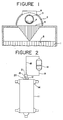
- this apparatus includes a header 2 forming a header chamber disposed on the top of a core 1 of a heat exchanger and extending along the length of the core 1, and a spreading pipe 3 extending along the length of the core 1 and having a plurality of spaced rows of holes 4 formed radially therein (ie each row of holes 4 extends radially about the centre line of the pipe 3) to spread the fluid across the top of the core.
- the liquid phase can be distributed to inlets 5 of downward flow passages 8 from the holes 4 of the spreading pipe 3 independently of the rate of distribution ofthe gas phase to the inlets 5 from a feed gas nozzle 6 via the header chamber 2.
- the holes 4 in each row are differentially spaced from each other, that is, in the disclosed apparatus the distance between adjacent holes 4 near an end of each row is smaller than the distance between adjacent holes 4 near the centre of each row in order to attain uniform distribution of liquid in the widthwise direction of the core 1, a greater amount of liquid will still be distributed at the centre than at opposite ends of each row. Accordingly, the apparatus is disadvantageous in that liquid is not distributed uniformly over the entire width of the core 1 and fluctuation of the amount of liquid will cause fluctuation of the distribution of the liquid.
- the present invention provides an apparatus for uniformly distributing a fluid including a gaseous and a liquid phase, said apparatus comprising a header which is disposed on the top of a core, said core having fluid inlets formed therein in a predetermined spaced relationship relative to each other and the header forming a chamber above said fluid inlets and a liquid spreading device disposed within and extending along the length of said header chamber, said liquid spreading device comprising a main pipe extending along the full length of said header chamber, characterised in that there are provided a plurality of upstanding feed gas nozzles connected to said header for feeding gas in a predetermined direction into said header chamber, a plurality of branch pipes connected to said main pipe and extending perpendicularly with reference to the axis of said main pipe, said branch pipes extending just above and along the full width of said fluid inlets of said core, the lower part of each of said branch pipes having a plurality of liquid spreading holes in a predetermined spaced relationship along the full length thereof arranged so as to distribute the fluid in the same direction as
- the heat exchanger includes a core 11, a header 12 for feeding a fluid having gaseous and liquid phases to the inlets of the downward flow -passages of the core 11, a feed gas nozzle 13 for feeding the gas phase of the fluid to the header 12, another header 14 for feeding the gas phase of the fluid to the header 12, and a gas/liquid separator 16 for separating the gaseous and liquid phases of the fluid fed thereto by way of a line 18.
- the gas phase is fed to a uniform distributor apparatus 20 by way of a line 18 and nozzle 13 while the liquid phase is fed to the apparatus 20 by way of another line 19.
- a pump may be provided for the line 19 for pumping the liquid to the uniform distributor apparatus 20.
- the apparatus 20 for uniformly distributing a fluid including a gaseous and a liquid phase includes the header 12 which forms a chamber above the inlets of the downward flow passages which inlets are provided in a predetermined spaced relationship on the top of the core 11.
- the apparatus further includes a pair of feed gas nozzles 13 which extend upwardly from the top of the header 12, and a liquid spreading device 21 extending within and along the length of the header 12.
- the liquid spreading device 21 includes a main pipe 22 extending along the full length of the header 12, a plurality of short pipes 23 secured to and located directly below the main pipe 22 in a predetermined spaced relationship relative to each other, and a plurality of branch pipes 24 each secured to the bottom end of a respective one of the short pipes 23 and extending perpendicularly to the main pipe 22 across the full width of the downward flow inlets 5 of the core 11.
- Each of the branch pipes 24 has a plurality of liquid spreading holes 25 passing through the bottom wall of the respective branch pipe 24, the set of holes being provided along the full length of each branch pipe 24 in a predetermined spaced relationship relative to each other.
- the main pipe 22 has a pair of feed liquid pipes 26 extending upwardly therefrom so that liquid may be fed by way of the feed liquid pipes 26 and the line 19.
- gas fed by way of the line 18 passes through the feed gas nozzle 13 and the chamber formed by the header 12 and is then dispersed to the inlets 5 of the downward flow passages of the core 11 similarly to the conventional manner, while liquid fed from the line 19 to the main pipe 22 of the liquid spreading device 21 is uniformly distributed to the individual inlets 5 of the downward flow passages from the branch pipes 24 located above the entrances 5.
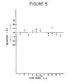
- the uniform distributor apparatus for uniformly distributing a fluid including a gaseous and a liquid phase can distribute liquid substantially uniformly with a deviation of less than plus or minus 10 percent. Besides, even if the flow rate fluctuates, the apparatus can follow such fluctuations and still distribute liquid uniformly.
Landscapes
- Chemical & Material Sciences (AREA)
- Engineering & Computer Science (AREA)
- Chemical Kinetics & Catalysis (AREA)
- Physics & Mathematics (AREA)
- Thermal Sciences (AREA)
- Mechanical Engineering (AREA)
- General Engineering & Computer Science (AREA)
- Organic Chemistry (AREA)
- Heat-Exchange Devices With Radiators And Conduit Assemblies (AREA)
- Details Of Heat-Exchange And Heat-Transfer (AREA)
- Feeding, Discharge, Calcimining, Fusing, And Gas-Generation Devices (AREA)
Claims (2)
Applications Claiming Priority (2)
| Application Number | Priority Date | Filing Date | Title |
|---|---|---|---|
| JP57161983A JPS5956696A (ja) | 1982-09-16 | 1982-09-16 | 気液二相流体の均一分配装置 |
| JP161983/82 | 1982-09-16 |
Publications (2)
| Publication Number | Publication Date |
|---|---|
| EP0106544A1 EP0106544A1 (de) | 1984-04-25 |
| EP0106544B1 true EP0106544B1 (de) | 1985-12-18 |
Family
ID=15745794
Family Applications (1)
| Application Number | Title | Priority Date | Filing Date |
|---|---|---|---|
| EP83305454A Expired EP0106544B1 (de) | 1982-09-16 | 1983-09-16 | Vorrichtung zur Verteilung von Medien, in der gasförmigen und flüssigen Phase |
Country Status (5)
| Country | Link |
|---|---|
| US (1) | US4544514A (de) |
| EP (1) | EP0106544B1 (de) |
| JP (1) | JPS5956696A (de) |
| DE (1) | DE3361568D1 (de) |
| DZ (1) | DZ574A1 (de) |
Families Citing this family (4)
| Publication number | Priority date | Publication date | Assignee | Title |
|---|---|---|---|---|
| IL107850A0 (en) * | 1992-12-07 | 1994-04-12 | Multistack Int Ltd | Improvements in plate heat exchangers |
| FR2716961B1 (fr) * | 1994-03-04 | 1996-06-14 | Packinox Sa | Dispositif d'injection d'un fluide sous pression dans un faisceau à plaques d'un échangeur thermique. |
| SE516537C2 (sv) * | 2000-05-19 | 2002-01-29 | Alfa Laval Ab | Plattpaket och plattvärmeväxlare |
| CN103486896B (zh) | 2013-07-30 | 2015-05-27 | 杭州三花微通道换热器有限公司 | 集流管组件和具有该集流管组件的换热器 |
Family Cites Families (11)
| Publication number | Priority date | Publication date | Assignee | Title |
|---|---|---|---|---|
| US1768162A (en) * | 1926-01-29 | 1930-06-24 | Koppers Co Inc | Apparatus for treating gases |
| GB413947A (en) * | 1933-12-06 | 1934-07-26 | Robert Morton & Company Ltd | Improvements in or relating to wort coolers and similar heat exchange apparatus |
| US2490080A (en) * | 1944-05-19 | 1949-12-06 | Francis L Melvill | Contacting apparatus |
| US2946726A (en) * | 1958-12-04 | 1960-07-26 | Jr Michael Markels | Horizontal distillation apparatus |
| US3079092A (en) * | 1959-07-13 | 1963-02-26 | Lizenzia A G | Liquid distributor for gas and liquid contact apparatus |
| US3282334A (en) * | 1963-04-29 | 1966-11-01 | Trane Co | Heat exchanger |
| US3419251A (en) * | 1965-06-21 | 1968-12-31 | Us Stoneware Inc | Distributor |
| GB1163288A (en) * | 1966-11-10 | 1969-09-04 | Zeitz Hydrierwerk | Liquid Distribution Device for Heat Exchangers |
| GB1337771A (en) * | 1972-08-16 | 1973-11-21 | Sim Chem Ltd | Apparatus for the distribution of liquids |
| SE423279B (sv) * | 1977-09-22 | 1982-04-26 | Munters Ab Carl | Tillforselanordning vid en evaporotiv kontaktkropp |
| US4299786A (en) * | 1980-10-28 | 1981-11-10 | Tower Systems Inc. | Waste heat disposal process |
-
1982
- 1982-09-16 JP JP57161983A patent/JPS5956696A/ja active Pending
-
1983
- 1983-09-15 DZ DZ836957A patent/DZ574A1/fr active
- 1983-09-16 EP EP83305454A patent/EP0106544B1/de not_active Expired
- 1983-09-16 DE DE8383305454T patent/DE3361568D1/de not_active Expired
- 1983-09-16 US US06/532,902 patent/US4544514A/en not_active Expired - Lifetime
Also Published As
| Publication number | Publication date |
|---|---|
| DE3361568D1 (en) | 1986-01-30 |
| EP0106544A1 (de) | 1984-04-25 |
| US4544514A (en) | 1985-10-01 |
| JPS5956696A (ja) | 1984-04-02 |
| DZ574A1 (fr) | 2004-09-13 |
Similar Documents
| Publication | Publication Date | Title |
|---|---|---|
| US4557877A (en) | Liquid distributor for an exchange column | |
| US6149136A (en) | Distributor for packed liquid-vapor contact column | |
| US5051214A (en) | Double-deck distributor and method of liquid distribution | |
| US4606745A (en) | Condenser-evaporator for large air separation plant | |
| JPS6017601A (ja) | 液体蒸発方法、液体蒸発用熱交換器および空気分離設備 | |
| US4317787A (en) | Device for distributing a liquid in thin-film form in vertical heat-exchangers | |
| US20040200602A1 (en) | System for stripping and rectifying a fluid mixture | |
| JPH0551340B2 (de) | ||
| US4436146A (en) | Shell and tube heat exchanger | |
| US5106544A (en) | Method of and apparatus for vapor distribution | |
| GB2158934A (en) | Heat exchanger | |
| US4510023A (en) | Perforated bubble caps for enhanced vapor/liquid contact on a distillation tray | |
| JPH09101095A (ja) | 状態調節の容易な熱交換器及び状態調節流体導入方法 | |
| EP2414090B1 (de) | Verbesserte flüssigkeitszufuhr für kontaktböden mit dampfflüssigkeits-parallelfluss | |
| EP1067347B1 (de) | Fallfilm-verdampfer als kondensationsverdampfer | |
| EP1316345B3 (de) | Flüssigkeitsverteiler mit innerem Leitelement | |
| EP0328786A1 (de) | Flüssigkeitsverteiler mit Prallplatten | |
| EP0106544A1 (de) | Vorrichtung zur Verteilung von Medien, in der gasförmigen und flüssigen Phase | |
| US5755279A (en) | Heat exchanger | |
| EP0378408B1 (de) | Doppelstöckiger Verteiler | |
| US7163051B2 (en) | Heat exchanger distributor for multicomponent heat exchange fluid | |
| US4301098A (en) | Vapor liquid contacting | |
| EP0688240B1 (de) | Wasserverteilung aus kühlturm | |
| US3911067A (en) | Direct contact gas condenser | |
| US11774189B2 (en) | Heat exchanger, hardway fin arrangement for a heat exchanger, and methods relating to same |
Legal Events
| Date | Code | Title | Description |
|---|---|---|---|
| PUAI | Public reference made under article 153(3) epc to a published international application that has entered the european phase |
Free format text: ORIGINAL CODE: 0009012 |
|
| 17P | Request for examination filed |
Effective date: 19830924 |
|
| AK | Designated contracting states |
Designated state(s): BE DE FR GB |
|
| GRAA | (expected) grant |
Free format text: ORIGINAL CODE: 0009210 |
|
| AK | Designated contracting states |
Designated state(s): BE DE FR GB |
|
| REF | Corresponds to: |
Ref document number: 3361568 Country of ref document: DE Date of ref document: 19860130 |
|
| ET | Fr: translation filed | ||
| PLBE | No opposition filed within time limit |
Free format text: ORIGINAL CODE: 0009261 |
|
| STAA | Information on the status of an ep patent application or granted ep patent |
Free format text: STATUS: NO OPPOSITION FILED WITHIN TIME LIMIT |
|
| 26N | No opposition filed | ||
| PGFP | Annual fee paid to national office [announced via postgrant information from national office to epo] |
Ref country code: BE Payment date: 19901108 Year of fee payment: 8 |
|
| PG25 | Lapsed in a contracting state [announced via postgrant information from national office to epo] |
Ref country code: BE Effective date: 19910930 |
|
| BERE | Be: lapsed |
Owner name: K.K. KOBE SEIKO SHO Effective date: 19910930 |
|
| REG | Reference to a national code |
Ref country code: GB Ref legal event code: IF02 |
|
| PGFP | Annual fee paid to national office [announced via postgrant information from national office to epo] |
Ref country code: FR Payment date: 20020910 Year of fee payment: 20 |
|
| PGFP | Annual fee paid to national office [announced via postgrant information from national office to epo] |
Ref country code: GB Payment date: 20020911 Year of fee payment: 20 |
|
| PGFP | Annual fee paid to national office [announced via postgrant information from national office to epo] |
Ref country code: DE Payment date: 20020925 Year of fee payment: 20 |
|
| PG25 | Lapsed in a contracting state [announced via postgrant information from national office to epo] |
Ref country code: GB Free format text: LAPSE BECAUSE OF EXPIRATION OF PROTECTION Effective date: 20030915 |
|
| REG | Reference to a national code |
Ref country code: GB Ref legal event code: PE20 |