EP0106508A2 - Spulnabeneinrichtung für Bandtransport - Google Patents
Spulnabeneinrichtung für Bandtransport Download PDFInfo
- Publication number
- EP0106508A2 EP0106508A2 EP83305259A EP83305259A EP0106508A2 EP 0106508 A2 EP0106508 A2 EP 0106508A2 EP 83305259 A EP83305259 A EP 83305259A EP 83305259 A EP83305259 A EP 83305259A EP 0106508 A2 EP0106508 A2 EP 0106508A2
- Authority
- EP
- European Patent Office
- Prior art keywords
- hub
- housing
- motor
- sun wheel
- carrier
- Prior art date
- Legal status (The legal status is an assumption and is not a legal conclusion. Google has not performed a legal analysis and makes no representation as to the accuracy of the status listed.)
- Granted
Links
Images
Classifications
-
- G—PHYSICS
- G11—INFORMATION STORAGE
- G11B—INFORMATION STORAGE BASED ON RELATIVE MOVEMENT BETWEEN RECORD CARRIER AND TRANSDUCER
- G11B15/00—Driving, starting or stopping record carriers of filamentary or web form; Driving both such record carriers and heads; Guiding such record carriers or containers therefor; Control thereof; Control of operating function
- G11B15/18—Driving; Starting; Stopping; Arrangements for control or regulation thereof
- G11B15/26—Driving record carriers by members acting directly or indirectly thereon
- G11B15/32—Driving record carriers by members acting directly or indirectly thereon through the reels or cores on to which the record carrier is wound
-
- G—PHYSICS
- G11—INFORMATION STORAGE
- G11B—INFORMATION STORAGE BASED ON RELATIVE MOVEMENT BETWEEN RECORD CARRIER AND TRANSDUCER
- G11B15/00—Driving, starting or stopping record carriers of filamentary or web form; Driving both such record carriers and heads; Guiding such record carriers or containers therefor; Control thereof; Control of operating function
- G11B15/60—Guiding record carrier
- G11B15/66—Threading; Loading; Automatic self-loading
- G11B15/662—Positioning or locking of spool or reel
-
- Y—GENERAL TAGGING OF NEW TECHNOLOGICAL DEVELOPMENTS; GENERAL TAGGING OF CROSS-SECTIONAL TECHNOLOGIES SPANNING OVER SEVERAL SECTIONS OF THE IPC; TECHNICAL SUBJECTS COVERED BY FORMER USPC CROSS-REFERENCE ART COLLECTIONS [XRACs] AND DIGESTS
- Y10—TECHNICAL SUBJECTS COVERED BY FORMER USPC
- Y10T—TECHNICAL SUBJECTS COVERED BY FORMER US CLASSIFICATION
- Y10T74/00—Machine element or mechanism
- Y10T74/19—Gearing
- Y10T74/19628—Pressure distributing
-
- Y—GENERAL TAGGING OF NEW TECHNOLOGICAL DEVELOPMENTS; GENERAL TAGGING OF CROSS-SECTIONAL TECHNOLOGIES SPANNING OVER SEVERAL SECTIONS OF THE IPC; TECHNICAL SUBJECTS COVERED BY FORMER USPC CROSS-REFERENCE ART COLLECTIONS [XRACs] AND DIGESTS
- Y10—TECHNICAL SUBJECTS COVERED BY FORMER USPC
- Y10T—TECHNICAL SUBJECTS COVERED BY FORMER US CLASSIFICATION
- Y10T74/00—Machine element or mechanism
- Y10T74/19—Gearing
- Y10T74/19637—Gearing with brake means for gearing
Definitions
- This invention relates to motor driven hubs for the support of supply or take-up reels in magnetic tape recording or playback machines, particularly though not exclusively a magnetic tape recorder adapted for the recording and playback of video-signals.
- the recorder may be arranged so that it can operate, with comparatively small size reels, with a lid closed but is versatile enough to take larger size reels which may require shifting of the supply and take-up reel hubs and the operation of the recorder with the lid removed.
- the shift of the supply or take-up reel hubs could be effected by simple pivoting but if ordinary forms of drive and drive coupling were:used for the hub, a complex coupling between the motor and the hub would be required.
- a further aspect of the invention arises from the considerations of efficiency and light weight, particularly for battery operated portable video tape recorders.
- a brushless DC machine is inherently efficient and can be made in a lightweight construction but since it is preferable to drive such a motor at high speed appropriate gearing is necessary between the motor and the hub.
- a further aspect of the present invention is therefore the design and manner of operation of a hub which includes its own motor and which also includes appropriate gearing between the motor and the rotating part of the hub.
- Another aspect of the invention lies in the features of construction which enable the hub which rotates and on which the reel is to be mounted to be removed easily from the rest of the hub unit without disturbing the remainder of the unit.
- a motor driven hub for holding and rotating a tape reel comprises a housing including at least a base and a side wall extending around the base, a rotary hub which is adapted for holding a reel of tape, the hub including a peripheral part which extends around the side wall and includes an inwardly directed ring of gear teeth, an electric motor, which may be a brushless DC motor, which is contained within the housing, a gear wheel which protrudes outwardly with respect to said side wall to engage said ring of gear teeth and means within the housing for coupling the motor to the gear wheel.
- an electric motor which may be a brushless DC motor
- the coupling means may comprise a sun wheel which is connected to be driven by the motor and the aforesaid gear wheel may constitute one of a pair of planet wheels evenly spaced around the sun wheel, each such planet wheel being in driving engagement with the sun wheel and protruding laterally of the side wall to engage the said ring.
- One important feature of such a coupling is the linking of the planet wheels so as to permit conjoint limited movement of the planets relative to the sun in a direction parallel to and transverse the line forming the centres of the planets. The transverse movement enables the sun to drive both planets evenly and the parallel movement, which is preferably resiliently resisted, reduces noise and promotes a smoother transmission of power.
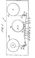
- Figure 1 illustrates in simplified form the principal parts of a video recorder.
- the recorder 1 is intended for recording signals or playing back signals from a magnetic tape 2 which is supplied by a supply reel driven by its own motor.
- a suitable construction for a hub supporting the reel 3 will be set forth with reference to Figure 2.
- From the supply reel the path of the tape 2 extends around a rotary guide 4 and thence to a guide 5 which is carried at one end of an arm 6 mounted for rotation coaxially with the guide 4.
- the purpose of the pivoted arm is to provide sensing of the tape tension in a loop formed around the guide 5. If the tension in the tape in this loop increases, the arm 6 will rotate.
- the rotation of the arm can be sensed by any convenient known means and used in known manner to control the motor which drives the reel 3 in order to maintain a substantially constant tension in the length of tape in the loop.
- the path of the tape extends past a guide 7, a video erase head 8, and around a pair of guides 9 controlling the entrance of the tape to a helical path extending around a drum 1 0 of which the axis 11 is slightly tilted relative to the general plane of the path of the tape.
- a motor driving around the periphery of the drum a scanning head for the scanning of the tape in oblique tracks, in a manner generally known per se.
- the tape passes around a pair of guides 12 and extends past a guide 13to capstan 14 which is provided with a pinch roller 15 for the maintenance of the tape in close proximity to the capstan.
- the tape path extends from the capstan past erase, audio and control track heads 16 to 18 and then around a further guide 19, a guide 20 mounted at one end of a pivoted arm 21 rotatable about a pivot, a further guide 22 which is coaxial with the pivot for the arm 21, and finally a take-up reel 23.
- the guide 20 acts in a manner similar to the guide 5, a pivoting movement of the arm 21 providing a measure of the tension in the loop of tape around the guide 20 and providing a control for the motor (not shown) which drives the take-up reel 23.
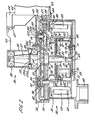
- Figure 2 illustrates in sectional form a preferred construction for a hub which is t Q support a supply reel or a take-up reel. It is important to note that the two halves of Figure 2 represent sections at right angles to each other.
- the hub unit comprises a housing 30 composed primarily of a circular base 31 and an upstanding peripheral side wall 32, and a rotary hub 33 which includes an axially directed peripheral portion or annulus 34 which extends around the side wall 32 of the housing and carries an internally toothed ring 35 of which the gear teeth face inwardly towards the side wall.
- the hub 33 is intended to be removable from the rest of the unit and for this purpose the central part of the hub has the shape of an inverted cup 36 which fits over a post 37 that carries an upper bearing 38 and a lower bearing 39 which mount the cup portion 36 for rotation about the axis of the cup.
- the hub 33 has a radial flange 40 extending outwardly from the bottom of the cup 36. The flange 40 terminates in a rim 41, the annular portion 34 forming an annular rebate with the rim 41.
- the hub is adapted to accommodate a reel 42 but the manner in which it does so is not of importance.
- the hub can carry reels at two different heights.
- the hub carries an assembly including radial ribs 43 which extend from the side wall of the cup 36 to near the periphery of the flange 40. These ribs are provided for strengthening and stiffening the hub 33.
- the reel 42 is shown as adjacent the annulus 34 and is supported between a flange 44 which forms part of an annulus 45 secured to the annulus 34 and a screw fixing 46 which engages a screw-threaded member 47 in engagement with the ribs 43.
- the hub is adapted differently, in a manner not relevant to the invention, the bottom side of the reel being then approximately level with the upper surface of-the base 31.
- the base 31 includes a downwardly extending post 48 which is eccentric relative to the rotary axis that extends centrally of the base and axially of the post 37 and the hub 33.
- the purpose of the downwardly extending post 48 is to provide a pivoted mount for the unit so that the unit can be pivoted from a position suitable for accommodating one size of reel to another position suitable for accommodating a different size of reel.
- the base 31 has a central aperture 49 which is surrounded by a short upstanding annular flange 50 accommodating a bearing 51 in which the lower, reduced diameter, end 52 of a shaft 53 is supported.
- the upper end 54 of the shaft 53 is received in a bearing 55 secured in a cover plate 56, which carries the post 37 and extends so as to form a top cover for the housing 30 at the side wall 32, the periphery of the plate 56 being accommodated within a rebate 57 in the upper inner margin of the side wall 32.
- the post 37 is shouldered at the top to carry the bearing 38 and has a groove 58 for a split ring 58a retaining a frusto-conical washer 58b to retain the'bearing 39 against a lug 58c which is externally adjustable by means of a screw 58d.
- the shaft 53 carries a sleeve 59 from which extends laterally a disc part or rotor 60 which carries at its periphery a cylindrical member 61 coaxial with and surrounding the rotor.
- the member 61 provides a mount for a plurality of permanent magnets 62 which produce the field system of the motor accommodated within the housing.
- the stator for this motor comprises windings shown schematically at 63 and carried in a plurality of narrow upstanding ribs 64 spaced apart around the periphery of the rotor, just inside the side wall 32 of the housing.
- the ribs 64 preferably support a magnetic return 65.
- the magnets 62 on the rotor, together with the windings 63 are the principal parts of a brushless DC motor.
- a brushless DC motor unlike an ordinary DC motor in which the field magnets are fixed and the energising windings rotate on an armature which has a commutator ring for switching the polarity of currents applied to the armature windings, the field magnets rotate and the windings are stationary.
- Brushless commutator motors are well-known in principle. It is also known that commutation for a brushless DC motor must be performed by an electrical switching circuit which however forms no part of the present invention and will not therefore be described.
- the magnets 62 are axially offset from the coils. 63 so that the rotor is, while driven, urged upwardly.
- a brake This is constituted by a disc 66 which carries pads 67 positioned to engage the underside of the rotor disc 60.
- the brake disc 66 is disposed over and in general register with a dish member including a cylindrical side wall 68 and a base plate 70.
- the plate 70 is attached to the'base 31 at appropriate angularly spaced intervals by means of bolts such as the bolts 71 extending through the base 31 to a nut 72 which engages the upper surface of the base plate 70 by means of a washer 73.
- a channel member 69 which thus provides an annular channel extending around the wall'68.
- spigots such as the spigot 74 which carries a collar 75 for the support of the lower end of a compression spring 76 which extends upwardly into a recess 77 formed at the periphery of the brake disc 66, so as to be in approximate register with the channel formed by the channel member 69.
- the springs such as the spring 76 provide a means for urging the brake disc into engagement, via the pads 67, with the rotor disc 60.
- bushings 78 supported in the channel member 69 by means of screws 79.
- the bushings each have a bore which receivesa respective downwardly extending spigot 80 carried on the brake disc 66. The spigots and bushes thereby provide for fixing of the brake disc 66 against rotation.
- a spool 81 below the brake disc, which is ferromagnetic, is a spool 81, of which the lower end 82 is accommodated in an aperture 83 formed in the base plate 70.
- the spool 81 carries a solenoid winding (not shown for convenience) energisation of which will attract the brake disc downwardly so as to permit the rotor disc 60 to rotate.
- the timing for the switching of a commutator circuit in a brushless commutator motor is preferably attained by sensing the rotation of the rotor and deriving pulse signals as the rotor passes through predetermined phase positions.
- the rotor disc 60 carries upstanding, short arcuate portions 84, which are coaxial with the rotor.
- the path of the arcuate portions 84 extends through a gap 85 in a core 86 on which is carried a sensing winding (not shown).
- the core 86 is carried on an arm 87 which is mounted by means of a mounting block 88 carried on an inwardly extending flange 89 from the side wall 32 of the housing 30.
- the number of sensing coils depends on the number of phases of the stator winding and the number of arcuate portions 84 depends upon the number of effective poles of the motor; there may be two portions 84 and two sensing coils, so that four pulses per revolution of the rotor are obtained.
- the shaft 53 carries a sun wheel 90 which is in geared connection with at least one planet wheel.
- a sun wheel 90 which is in geared connection with at least one planet wheel.
- Each planet wheel is mounted so as to protrude slightly from the side wall 32 of the housing and thereby to engage the teeth of the internally toothed ring 35.
- the plate 56 For mounting the planets, the plate 56 has angularly spaced apertures 92 over which is mounted a carrier in the form of a ring 93 which for each aperture 92 has a countersunk bore 94 for a shaft 95.
- This shaft carries or is formed integrally with a collar 96 between which and a clip 97 is supported a bearing 98 for the planet 91.
- apertures 92 spaced at 90° intervals. Two opposite apertures provide a mounting of the ring 93 to the rim or frame 41, the manner of mounting being illustrated for the right hand aperture 92a in Figure 2.
- the aperture 92a has an upper part 98 of smaller diameter and a lower part 99 of larger diameter forming a recess in the plate 56. Through the aperture 92a extends a short spigot 100 which is supported by the countersunk bore 94a and carries a collar 101 which fits loosely in the recess constituted by the lower part 99 of the aperture 92a. The collar traps within the upper part 98 of the aperture 92a a ring 102 of rubber or other resilient material.
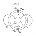
- the arrangement of the sun wheel 90, the planets 91, the annulus 34, the ring 93, the apertures 92a, the spigot 100 and the rings 102 is shown in Figure 3. .
- the apertures 92a are shown elongate in a direction transverse the imaginary line between the axes of the planets 91 for the purpose of explanation. Although the apertures 92a could be thus formed, in the actual embodiment illustrated in Figure 2 the rings 102 are shaped so that the spigots have some free movement in the direction which is radial with respect to the sun wheel and have some, resiliently opposed movement in the direction which is circumferential with respect to the sun wheel (these directions being denoted by the arrows A and B respectively). Both movements are limited by the collars 101 and the recesses 99.
- the movement in the direction of the arrow B smooths out irregularities in the gears, reduces noise and assists in maintaining balance in the drive to the annulus.
- the rings 102 are preferably as described, they may be simply circular so that both the movements mentioned are resiliently resisted. Such a form for the rings may be appropriate if there are more than two evenly spaced planet wheels and more than two apertures 92a and associated groups of components.
Landscapes
- Connection Of Motors, Electrical Generators, Mechanical Devices, And The Like (AREA)
- Storage Of Web-Like Or Filamentary Materials (AREA)
- Winding Of Webs (AREA)
- Advancing Webs (AREA)
Priority Applications (1)
| Application Number | Priority Date | Filing Date | Title |
|---|---|---|---|
| AT83305259T ATE51975T1 (de) | 1982-09-17 | 1983-09-08 | Spulnabeneinrichtung fuer bandtransport. |
Applications Claiming Priority (2)
| Application Number | Priority Date | Filing Date | Title |
|---|---|---|---|
| GB8226571 | 1982-09-17 | ||
| GB8226571 | 1982-09-17 |
Publications (3)
| Publication Number | Publication Date |
|---|---|
| EP0106508A2 true EP0106508A2 (de) | 1984-04-25 |
| EP0106508A3 EP0106508A3 (en) | 1986-05-14 |
| EP0106508B1 EP0106508B1 (de) | 1990-04-11 |
Family
ID=10532991
Family Applications (1)
| Application Number | Title | Priority Date | Filing Date |
|---|---|---|---|
| EP83305259A Expired - Lifetime EP0106508B1 (de) | 1982-09-17 | 1983-09-08 | Spulnabeneinrichtung für Bandtransport |
Country Status (5)
| Country | Link |
|---|---|
| US (1) | US4542663A (de) |
| EP (1) | EP0106508B1 (de) |
| JP (1) | JPS5992852A (de) |
| AT (1) | ATE51975T1 (de) |
| DE (1) | DE3381458D1 (de) |
Family Cites Families (11)
| Publication number | Priority date | Publication date | Assignee | Title |
|---|---|---|---|---|
| US1348539A (en) * | 1917-03-23 | 1920-08-03 | Julius M Breitenbach | Electric motor |
| US2716005A (en) * | 1953-04-30 | 1955-08-23 | Eastman Kodak Co | Reel driving mechanism for motionpicture projectors |
| DE1082091B (de) * | 1958-09-20 | 1960-05-19 | Boelkow Entwicklungen Kg | Reibradgetriebe, dessen UEbersetzung sich bei Umkehr der Drehrichtung des treibendenTeiles aendert, insbesondere fuer Magnettongeraete |
| US3153515A (en) * | 1962-03-15 | 1964-10-20 | Scully Recording Instr Corp | Differential braking system for tape transport mechanism |
| US3498571A (en) * | 1968-08-13 | 1970-03-03 | Interface Mechanisms | Tape reel drive system |
| US3690198A (en) * | 1970-11-04 | 1972-09-12 | Motorola Inc | Fast forward tape advance |
| JPS5241766A (en) * | 1975-09-30 | 1977-03-31 | Teijin Seiki Co Ltd | Planetary gear type transmission |
| JPS5815854B2 (ja) * | 1977-04-19 | 1983-03-28 | 日本ビクター株式会社 | テ−プ駆動装置 |
| US4292557A (en) * | 1978-05-10 | 1981-09-29 | Sony Corporation | Motor with integral clutch |
| US4303210A (en) * | 1978-12-13 | 1981-12-01 | Hitachi, Ltd. | Tape drive device |
| ATE10053T1 (de) * | 1980-06-17 | 1984-11-15 | Acec | Getriebemotor mit bremse. |
-
1983
- 1983-09-08 JP JP58165840A patent/JPS5992852A/ja active Granted
- 1983-09-08 AT AT83305259T patent/ATE51975T1/de active
- 1983-09-08 EP EP83305259A patent/EP0106508B1/de not_active Expired - Lifetime
- 1983-09-08 DE DE8383305259T patent/DE3381458D1/de not_active Expired - Lifetime
- 1983-09-15 US US06/533,094 patent/US4542663A/en not_active Expired - Lifetime
Also Published As
| Publication number | Publication date |
|---|---|
| US4542663A (en) | 1985-09-24 |
| EP0106508B1 (de) | 1990-04-11 |
| DE3381458D1 (de) | 1990-05-17 |
| ATE51975T1 (de) | 1990-04-15 |
| JPS5992852A (ja) | 1984-05-29 |
| EP0106508A3 (en) | 1986-05-14 |
| JPH0138736B2 (de) | 1989-08-16 |
Similar Documents
| Publication | Publication Date | Title |
|---|---|---|
| US5602694A (en) | Capstanless helical drive system | |
| NL192472C (nl) | Bandopneem- en/of weergeefinrichting. | |
| US2300778A (en) | Sound reproducer drive | |
| US4001887A (en) | Manual tape apparatus with generator for providing electrical power | |
| GB1518618A (en) | Direct drive for record player turntables | |
| US4767958A (en) | Stepping motor actuator with two interposed pole tooth pairs | |
| KR100245150B1 (ko) | 구동력 전달기구 | |
| US4542663A (en) | Reel hub assembly for tape transport | |
| US4521706A (en) | Tape driving capstan powered with a permanent magnet motor | |
| US5024162A (en) | Cable transport apparatus | |
| HK9296A (en) | Head wheel arrangement for a recorder | |
| US4611168A (en) | Magnetic tachometer assembly | |
| US2655563A (en) | Magnetic reproducing service for automobiles | |
| US3666193A (en) | Tape reel drive turntable | |
| US2495125A (en) | Wire recorder turret | |
| US4098474A (en) | Tape drive for a cassette in a sound reproducer and/or recorder | |
| KR0119481Y1 (ko) | 테이프 레코더의 헤드드럼 구조체 | |
| SU468298A1 (ru) | Устройство дл записи информации на магнитные диски | |
| JPH0210594Y2 (de) | ||
| JPH05168208A (ja) | 周波数発振器のステータ | |
| JPS6117567Y2 (de) | ||
| KR100312720B1 (ko) | 자기기록재생기의드럼모터를이용한테이프가이드장치 | |
| SU871213A2 (ru) | Лентопрот жный механизм | |
| JPH0232699B2 (ja) | Teepusokosochi | |
| JP2506632B2 (ja) | ピックアップの駆動装置 |
Legal Events
| Date | Code | Title | Description |
|---|---|---|---|
| PUAI | Public reference made under article 153(3) epc to a published international application that has entered the european phase |
Free format text: ORIGINAL CODE: 0009012 |
|
| AK | Designated contracting states |
Designated state(s): AT BE CH DE FR GB IT LI LU NL SE |
|
| PUAL | Search report despatched |
Free format text: ORIGINAL CODE: 0009013 |
|
| AK | Designated contracting states |
Kind code of ref document: A3 Designated state(s): AT BE CH DE FR GB IT LI LU NL SE |
|
| 17P | Request for examination filed |
Effective date: 19860903 |
|
| 17Q | First examination report despatched |
Effective date: 19880211 |
|
| GRAA | (expected) grant |
Free format text: ORIGINAL CODE: 0009210 |
|
| AK | Designated contracting states |
Kind code of ref document: B1 Designated state(s): AT BE CH DE FR GB IT LI LU NL SE |
|
| PG25 | Lapsed in a contracting state [announced via postgrant information from national office to epo] |
Ref country code: SE Effective date: 19900411 Ref country code: LI Effective date: 19900411 Ref country code: IT Free format text: LAPSE BECAUSE OF FAILURE TO SUBMIT A TRANSLATION OF THE DESCRIPTION OR TO PAY THE FEE WITHIN THE PRESCRIBED TIME-LIMIT;WARNING: LAPSES OF ITALIAN PATENTS WITH EFFECTIVE DATE BEFORE 2007 MAY HAVE OCCURRED AT ANY TIME BEFORE 2007. THE CORRECT EFFECTIVE DATE MAY BE DIFFERENT FROM THE ONE RECORDED. Effective date: 19900411 Ref country code: CH Effective date: 19900411 Ref country code: BE Effective date: 19900411 |
|
| REF | Corresponds to: |
Ref document number: 51975 Country of ref document: AT Date of ref document: 19900415 Kind code of ref document: T |
|
| REF | Corresponds to: |
Ref document number: 3381458 Country of ref document: DE Date of ref document: 19900517 |
|
| ET | Fr: translation filed | ||
| REG | Reference to a national code |
Ref country code: CH Ref legal event code: PL |
|
| PG25 | Lapsed in a contracting state [announced via postgrant information from national office to epo] |
Ref country code: LU Free format text: LAPSE BECAUSE OF NON-PAYMENT OF DUE FEES Effective date: 19900930 |
|
| PGFP | Annual fee paid to national office [announced via postgrant information from national office to epo] |
Ref country code: NL Payment date: 19900930 Year of fee payment: 8 |
|
| PLBE | No opposition filed within time limit |
Free format text: ORIGINAL CODE: 0009261 |
|
| STAA | Information on the status of an ep patent application or granted ep patent |
Free format text: STATUS: NO OPPOSITION FILED WITHIN TIME LIMIT |
|
| 26N | No opposition filed | ||
| PGFP | Annual fee paid to national office [announced via postgrant information from national office to epo] |
Ref country code: AT Payment date: 19910909 Year of fee payment: 9 |
|
| PG25 | Lapsed in a contracting state [announced via postgrant information from national office to epo] |
Ref country code: NL Effective date: 19920401 |
|
| NLV4 | Nl: lapsed or anulled due to non-payment of the annual fee | ||
| PG25 | Lapsed in a contracting state [announced via postgrant information from national office to epo] |
Ref country code: AT Effective date: 19920908 |
|
| PGFP | Annual fee paid to national office [announced via postgrant information from national office to epo] |
Ref country code: GB Payment date: 19930901 Year of fee payment: 11 |
|
| PGFP | Annual fee paid to national office [announced via postgrant information from national office to epo] |
Ref country code: DE Payment date: 19930908 Year of fee payment: 11 |
|
| PGFP | Annual fee paid to national office [announced via postgrant information from national office to epo] |
Ref country code: FR Payment date: 19930909 Year of fee payment: 11 |
|
| REG | Reference to a national code |
Ref country code: GB Ref legal event code: 732E |
|
| PG25 | Lapsed in a contracting state [announced via postgrant information from national office to epo] |
Ref country code: GB Effective date: 19940908 |
|
| GBPC | Gb: european patent ceased through non-payment of renewal fee |
Effective date: 19940908 |
|
| PG25 | Lapsed in a contracting state [announced via postgrant information from national office to epo] |
Ref country code: FR Effective date: 19950531 |
|
| PG25 | Lapsed in a contracting state [announced via postgrant information from national office to epo] |
Ref country code: DE Effective date: 19950601 |
|
| REG | Reference to a national code |
Ref country code: FR Ref legal event code: ST |