EP0106483B1 - Piezoelektrischer Versetzungsapparat - Google Patents
Piezoelektrischer Versetzungsapparat Download PDFInfo
- Publication number
- EP0106483B1 EP0106483B1 EP83305091A EP83305091A EP0106483B1 EP 0106483 B1 EP0106483 B1 EP 0106483B1 EP 83305091 A EP83305091 A EP 83305091A EP 83305091 A EP83305091 A EP 83305091A EP 0106483 B1 EP0106483 B1 EP 0106483B1
- Authority
- EP
- European Patent Office
- Prior art keywords
- displacing
- displacement
- members
- piezoelectric
- amount
- Prior art date
- Legal status (The legal status is an assumption and is not a legal conclusion. Google has not performed a legal analysis and makes no representation as to the accuracy of the status listed.)
- Expired
Links
Images
Classifications
-
- H—ELECTRICITY
- H02—GENERATION; CONVERSION OR DISTRIBUTION OF ELECTRIC POWER
- H02N—ELECTRIC MACHINES NOT OTHERWISE PROVIDED FOR
- H02N2/00—Electric machines in general using piezoelectric effect, electrostriction or magnetostriction
- H02N2/02—Electric machines in general using piezoelectric effect, electrostriction or magnetostriction producing linear motion, e.g. actuators; Linear positioners ; Linear motors
-
- G—PHYSICS
- G12—INSTRUMENT DETAILS
- G12B—CONSTRUCTIONAL DETAILS OF INSTRUMENTS, OR COMPARABLE DETAILS OF OTHER APPARATUS, NOT OTHERWISE PROVIDED FOR
- G12B1/00—Sensitive elements capable of producing movement or displacement for purposes not limited to measurement; Associated transmission mechanisms therefor
-
- H—ELECTRICITY
- H10—SEMICONDUCTOR DEVICES; ELECTRIC SOLID-STATE DEVICES NOT OTHERWISE PROVIDED FOR
- H10N—ELECTRIC SOLID-STATE DEVICES NOT OTHERWISE PROVIDED FOR
- H10N30/00—Piezoelectric or electrostrictive devices
- H10N30/50—Piezoelectric or electrostrictive devices having a stacked or multilayer structure
- H10N30/503—Piezoelectric or electrostrictive devices having a stacked or multilayer structure having a non-rectangular cross-section in a plane orthogonal to the stacking direction, e.g. polygonal or circular in top view
Definitions
- the present invention relates to a piezoelectric displacing device which utilizes the longitudinal effect of a piezoelectric material.
- a longitudinal effect-type piezoelectric displacing device when a signal voltage is applied to a piezoelectric element, the element expands/ contracts in the direction along the axis of an electric field acting thereupon. Thus, if one end of the element is fixed in position, the other end thereof is displaced.
- the element of such a device generally consists of PZT or a ternary polycrystalline material.
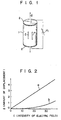
- the, piezoelectric material is formed into a column 1, and a DC high voltage is applied to the column along an axis parallel to the central axis of the column 1 for polarization along this axis, as shown in Fig. 1.
- the polarized element has a "polarization direction" along the axis parallel to the central axis, and exhibits piezoelectricity which depends on this polarization direction.
- electrodes 2 are formed on two end faces of the column 1 and a signal voltage V 1 is applied between the electrodes 2 so as to apply an electric field in the polarization direction
- the element expands/contracts in the direction of the axis parallel to the central axis of the column 1 in correspondence with the polarity of the voltage applied.
- a polarization axis P, an electric field axis E and a displacement axid 6 coincide with each other, this is referred to as the "longitudinal effect" of a piezoelectric material.
- the amount of displacement of a longitudinal effect-type piezoelectric displacing device is proportional to the product of an intensity of an electric field (a ratio of the signal voltage applied between the electrodes in the example of the element described above to the thickness of the piezoelectric material between the electrodes) and the size of the element along the electric field axis, that is, the length of the column.
- an intensity of an electric field a ratio of the signal voltage applied between the electrodes in the example of the element described above to the thickness of the piezoelectric material between the electrodes
- the size of the element along the electric field axis that is, the length of the column.
- the amount of displacement that is, change, reaches saturation, and the degree of polarization decreases depending upon the polarity of the electric field applied. Accordingly, the degree to which the intensity of the electric field may be increased is limited; it is usually 10 to 50% of the coersive field depending on the piezoelectric material
- the second method as described above a device mounting such an element with an increased length becomes large in size, thus preventing actual adoption of this method. Accordingly, the amount of displacement of a longitudinal effect-type piezoelectric displacing device is limited due to limits on the intensity of the electric field applied and the size of the device along the displacement axis.
- the upper limit of the piezoelectric constant associated with displacement is about 500 ⁇ 10 -12 m/V and the maximum intensity of the electric field within a normal operation range is about 1 kV/mm.
- the column has a length of 10 cm, an amount of displacement of only about 50 ⁇ m is obtained.
- Such a longitudinal effect-type piezoelectric displacing device can be applied to various types of measuring equipment, a precision displacing device such as a processor, or a precision drive apparatus such as an X-Y table.
- a piezoelectric displacing device is known to have an important defect. More specifically, displacement of an element has a hysteresis characteristic with respect to an applied electric field, so that the amount of displacement and the intensity of the electric field are not linear.
- Such residual displacement may be reduced by forming a displacing element having a structure which provides an increased amount of displacement for a given applied electric field.
- This method is established based on the following.
- the displacement of an element of a piezoelectric displacing device is substantially linearly proportional to the intensity of an electric field
- the residual displacement is substantially proportional to the power of ⁇ (where (3>1) of the electric field.
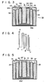
- Fig. 2 demonstrates this wherein the amount of displacement 6 is plotted along the axis of ordinate and the intensity of the electric field E is plotted along the axis of abscissa.
- Curve a shows the relationship between the amount of displacement of the element and the intensity of the elelUric field.
- Curve b shows the relationship between the residual displacement and the intensity of the electric field.
- the residual displacement after obtaining a given displacement is proportional to E 1 ⁇ before the displacement sensitivity is increased, it is proportional to N(E l /N) P after the displacement sensitivity is increased to N times the original value. This means that when the displacement sensitivity is increased to N times the original value, the residual displacement can be reduced to 1/N P - l .
- a piezoelectric displacing device having a new structure which has a constant element length along the displacement axis and which has an improved displacement sensitivity
- a piezoelectric displacing device can be provided which is small in size, and is less subject to a hysteresis characteristic; that is, which has an excellent linear response characteristic of a displacement with respect to the intensity of an electric field.
- EP-A-0 054 704 discloses a piezoelectric displacing device having displacing means including a plurality of displacing members.
- Each displacing member includes a plurality of stacked longitudinal effect type piezoelectric elements, the piezoelectric elements in each displacing member being stacked such that the displacement axes thereof are in the same direction.
- the displacing members are arranged juxtaposed to each other in a direction normal to the displacement axes of the piezoelectric elements and serve to convert a voltage applied thereto to a mechanical displacement.
- the displacing members are coupled to give the output displacement of the device.
- an object of the present invention to provide a longitudinal effect-type piezoelectric displacing device, which is capable of increasing the amount of displacement without requiring an increase in the overall length, and which has a small hysteresis characteristic and an excellent displacement sensitivity.
- a piezoelectric displacing device comprising displacing means including a plurality of displacing members each including a plurality of stacked longitudinal effect type piezoelectric elements, said piezoelectric elements in each displacing member being stacked such that the displacement axes thereof are in the same direction, said displacing members being arranged juxtaposed to each other in a direction normal to the displacement axes of said piezoelectric elements and serving to a voltage applied thereto to a mechanical displacement; and connecting means for mechanically connecting said piezoelectric displacing members, characterized in that the connecting means comprises a plurality of connecting members, in that each of said connecting members has a first member extending parallel to said displacement axes and arranged between adjacent displacing members, a second member extending from said first member to one of said adjacent displacing members and a third member extending from said first member to the other of said adjacent displacing members, said second and third members being connected at different positions along the displacement
- the displacement for a given intensity of the applied electric field increases proportionally to the number of displacing members connected without requiring a change in the size of each displacing member along its displacement axis.
- the length of the displacing member in order to increase the amount of displacement and sensitivity for a given intensity of an applied electric field, the length of the displacing member can only be increased along the electric field axis (displacement axis).
- the length of the displacing member must be increased to N times the original length along the axis of the displacing member as to increase the amount of displacement to N times the original displacement. This makes the overall device elongated and prevents easy mounting of the device.
- the amount of displacement can be increased to N times the original amount by incorporating N displacing members each having N elements, which are mechanically connected in series with each other. For this reason, the amount of displacement can be increased while keeping the length of the displacing members substantially the same as that of the conventional device. In this case, the total sectional area of the members is increased only to NxN times that before mechanical series connection. Accordingly, a longitudinal effect-type piezoelectric displacing device is provided which is relatively small in size and which can increase the amount of displacement, that is, displacement sensitivity for a given intensity of an electric field.
- the device of the present invention is advantageous in that it allows assembly of a compact system. Furthermore, the device of the present invention is compact in size, provides a larger amount of displacement, and has an excellent displacing characteristic with less residual displacement. Since the device of the present invention does not use a special displacement amplifying mechanism, a conventional problem of ruggedness is not presented.
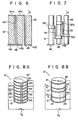
- Fig. 3 shows a piezoelectric displacing device 30 according to the first embodiment of the present invention.
- the device 30 has a columnar piezoelectric displacing member 31 and three cylndrical piezoelectric displacing members 32, 33 and 34 which have substantially the same length; and three cylindrical connectors 35, 36 and 37 with bottoms which mechanically connect the members 31,32,33 and 34 in series with each other.
- Each cylindrical connector 35, 36 or 37 has an annular flange 35a, 36a or 37a which extends horizontally outward from the open edge thereof.
- the columnar displacing member 31 is concentrically housed in the first cylindrical connector 35 at a distance therefrom, and has its lower end face fixed to the bottom surface of the cylindrical connector 35. A free end 31a of the member 31 projects beyond the flange 35a of the connector 35.
- the first cylindrical displacing member 32 is arranged to concentrically surround the first connector 35 at a distance therefrom.
- the upper end face of the member 32 engages with and is fixed to the rear surface of the flange 35a of the connector 35.
- the lower end face of the member 32 is fixed to and is supported by the bottom surface of the second connector 36 concentrically holding it therein at a distance therefrom.
- the bottom surface of the connector 36 is spaced apart from the bottom surface of the connector 35.
- the second cylindrical displacing member 33 is arranged to concentrically surround the connector 36 at a distance therefrom.
- the upper end face of the member 33 engages with and is fixed to the rear surface of the flange 36a of the connector 36.
- the lower end face of the member 33 is fixed to and is supported by the bottom surface of the third connector 37 concentrically holding it therein at a distance therefrom.
- the third cylindrical displacing member 34 concentrically surrounds the third cylindrical connector 37 at a distance therefrom.
- the upper end face of the member 34 engages with and is fixed to the rear surface of the flange 37a of the connector 37.
- the lower end face of the member 34 is fixed to and is supported by a bottom surface 38b of a casing 38 for holding the overall device therein.
- the bottom surface 38b of the casing 38 is spaced apart from the bottom surface of the connector 37.
- a window larger than the member 31 is formed in a position of a top surface 38a of the casing 38 which corresponds to the member 31 so as to allow passage of the member 31 therethrough.
- the lower end of the member 34 is a fixed end of the overall device, and the upper end 31 a of the member 31 is the free end E of the overall device.
- the piezoelectric displacing device 30 having the structure as described above displaces (expands/contracts) from point A as shown by arrows in Fig. 4.
- the member 34 displaces about the point A
- the member 33 displaces about point B
- the member 32 displaces about point C
- the member 31 displaces about point D.
- the free end E (the upper end 31 a of the member 31) is moved upward or downward according to a polarity of the applied electric field.
- the length of the overall device remains substantially the same as that of each displacing member
- a displacement characteristic equivalent to that of a member of a length substantially four times that of a single member used in the device of the present invention can be obtained.
- the amount of displacement at the point E shown in Fig. 4 for a given intensity of an applied electric field can be about four times that obtained when a single displacing member is used.
- Fig. 5 shows a modification of the device shown in Fig. 3.
- the same reference numerals as used in Fig. 3 denote the same parts, and a detailed description thereof will be omitted.
- the device shown in Fig. 5 has a connector 35' obtained by inverting the connector 35 of the device shown in Fig. 3.
- the upper and lower ends of the columnar displacing member 31 are fixed between the closed end of the connector 35' and the bottom surface of the connector 36.
- the lower end face of the first cylindrical displacing member 32 is fixed to and is supported by a flange 35a' of the connector 35'.
- the bottom surfaces of the flange 35a' and the connector 36 are spaced apart from each other.
- the upper end (free end) of the first cylindrical displacing member 32 projects above the top surface of the connector 35' and a disc plate 39 covers the upper, open end of the connector 35'.
- the disc plate 39 provides a wide displacement surface.
- Fig. 6 shows another embodiment of the present invention wherein three columnar piezoelectric displacing members 41,42 and 43 of the same length are connected by two connectors (cranks) 44 and 45 such that the displacements are in series with each other.
- the lower end of the member 41 is fixed to a stationary base 46 and the upper end thereof is fixed to an upper branch 44a of the crank 44.
- the lower end of the member 42 is fixed to and is supported by a lower branch 44b of the crank 44 extending in a direction opposite to the upper branch 44a.
- the upper end of the member 42 is fixed to an upper branch 45a of the crank 45.
- the lower end of the member 43 is fixed to and is supported by a lower branch 45b of the crank 45, and the upper end thereof is a free end at which displacement of the device occurs.
- Fig. 7 shows an embodiment wherein respective columnar piezoelectric displacing members 41, 42 and 43 are connected at their intermediate portions by connectors 51 and 52.
- Each connector 51 or 52 has clamps 51a a and 51b or 52a and 52b for clamping and holding the members 41, 42 and 43.
- each connector connects adjacent displacing members at different positions along the displacement axis.
- each piezoelectric displacing member such as a columnar displacing member 31 preferably has a structure wherein a piezoelectric material material such as a ternary piezoelectric material (Pb, Sr) [(Y"Z Nb"2), Ti, Zr]0 3 is formed into a disc shape, and resultant disc-shaped piezoelectric elements 61 are stacked through respective electrodes 65, as shown in Fig. 8A.
- a piezoelectric material material such as a ternary piezoelectric material (Pb, Sr) [(Y"Z Nb"2), Ti, Zr]0 3
- each element 61 can have a different length along the axial direction of the element. Also, a voltage can be applied only to selected elements using switches S so as to freely adjust the amount of displacement. Then, the amount of displacement of the free end E of the displacing member 31 can be finely adjusted, and the range of adjustment is widened.
- each connector is preferably formed of a material such as stainless steel, which has a great tensile strength, a small Young's modulus and a small coefficient of thermal expansion.
- the amount of displacement can be further freely adjusted, and the length thereof can be increased/decreased freely.
- Some of the piezoelectric displacing members may be fixed to have opposite directions of expansion/contraction and can be used as adjusting elements.
Landscapes
- General Electrical Machinery Utilizing Piezoelectricity, Electrostriction Or Magnetostriction (AREA)
- Control Of Position Or Direction (AREA)
Claims (5)
Applications Claiming Priority (2)
| Application Number | Priority Date | Filing Date | Title |
|---|---|---|---|
| JP57152554A JPS5943582A (ja) | 1982-09-03 | 1982-09-03 | 圧電変位装置 |
| JP152554/82 | 1982-09-03 |
Publications (3)
| Publication Number | Publication Date |
|---|---|
| EP0106483A2 EP0106483A2 (de) | 1984-04-25 |
| EP0106483A3 EP0106483A3 (en) | 1987-01-21 |
| EP0106483B1 true EP0106483B1 (de) | 1989-12-13 |
Family
ID=15542999
Family Applications (1)
| Application Number | Title | Priority Date | Filing Date |
|---|---|---|---|
| EP83305091A Expired EP0106483B1 (de) | 1982-09-03 | 1983-09-02 | Piezoelektrischer Versetzungsapparat |
Country Status (5)
| Country | Link |
|---|---|
| US (1) | US4510412A (de) |
| EP (1) | EP0106483B1 (de) |
| JP (1) | JPS5943582A (de) |
| CA (1) | CA1202352A (de) |
| DE (1) | DE3380976D1 (de) |
Families Citing this family (29)
| Publication number | Priority date | Publication date | Assignee | Title |
|---|---|---|---|---|
| JPS6086880A (ja) * | 1983-10-19 | 1985-05-16 | Nec Corp | 電歪効果素子 |
| US4895574A (en) * | 1984-06-06 | 1990-01-23 | Larry Rosenberg | Piezoelectric motivator for prosthetic devices |
| JPS61108182A (ja) * | 1984-11-01 | 1986-05-26 | Toshiba Corp | 積層形圧電素子装置とその使用方法 |
| JPS61167785A (ja) * | 1985-01-17 | 1986-07-29 | Nippon Denso Co Ltd | 圧電素子を利用した作動装置 |
| DE3626507A1 (de) * | 1985-08-06 | 1987-02-19 | Canon Kk | Betaetigungsvorrichtung |
| JPH0436138Y2 (de) * | 1985-09-02 | 1992-08-26 | ||
| JPS62141791A (ja) * | 1985-12-16 | 1987-06-25 | Nec Corp | セラミツク変位素子 |
| JPS62179783A (ja) * | 1986-02-04 | 1987-08-06 | Olympus Optical Co Ltd | 圧電式アクチユエ−タ |
| JPH0732273B2 (ja) * | 1986-05-22 | 1995-04-10 | 日本電気株式会社 | 電歪効果素子 |
| JPS63120480A (ja) * | 1986-11-10 | 1988-05-24 | Tokin Corp | 積層型圧電アクチユエ−タ |
| JPS63207185A (ja) * | 1987-02-23 | 1988-08-26 | Toyota Motor Corp | 圧電アクチユエ−タ |
| US4814622A (en) * | 1987-11-06 | 1989-03-21 | Bell Communications Research, Inc. | High speed scanning tunneling microscope |
| US5095725A (en) * | 1989-05-12 | 1992-03-17 | Fuji Electric Co., Ltd. | Press and actuator using piezoelectric element |
| GB8928952D0 (en) * | 1989-12-21 | 1990-02-28 | Queensgate Instr Ltd | Piezo-electric actuators |
| DE4116270C2 (de) * | 1990-05-18 | 2002-01-17 | Toyo Tire & Rubber Co | Dämpfungseinrichtung |
| US5206557A (en) * | 1990-11-27 | 1993-04-27 | Mcnc | Microelectromechanical transducer and fabrication method |
| US5173605A (en) * | 1991-05-02 | 1992-12-22 | Wyko Corporation | Compact temperature-compensated tube-type scanning probe with large scan range and independent x, y, and z control |
| DE4230799C1 (de) * | 1992-09-15 | 1994-03-31 | Freudenberg Carl Fa | Aktiver Schwingungstilger |
| DE4230800A1 (de) * | 1992-09-15 | 1994-03-17 | Freudenberg Carl Fa | Aktives Stellelement |
| US5367500A (en) * | 1992-09-30 | 1994-11-22 | The United States Of America As Represented By The Secretary Of The Navy | Transducer structure |
| JP2542154B2 (ja) * | 1992-11-26 | 1996-10-09 | 山一電機株式会社 | 圧電アクチェ―タ― |
| US5479061A (en) * | 1992-12-31 | 1995-12-26 | University Of North Carolina | Pleated sheet microelectromechanical transducer |
| US5925969A (en) * | 1995-10-17 | 1999-07-20 | O'neill; Cormac G. | Ferroelectric transducers |
| DE19712923A1 (de) * | 1997-03-27 | 1998-10-01 | Bosch Gmbh Robert | Piezoelektrischer Aktor |
| JP2000262076A (ja) * | 1999-03-05 | 2000-09-22 | Honda Motor Co Ltd | 超磁歪アクチュエータ |
| US6297576B1 (en) * | 2000-06-22 | 2001-10-02 | Agilent Technologies, Inc. | Piezoelectric actuator |
| US20040207293A1 (en) * | 2003-04-17 | 2004-10-21 | Seeley Charles Erklin | Telescoping piezoelectric actuator |
| US8297133B2 (en) * | 2005-06-20 | 2012-10-30 | S.W.A.C. Schmitt-Walter Automation Consult Gmbh | Pressure sensor |
| JP6778958B2 (ja) | 2016-04-07 | 2020-11-04 | マイクロファイン・マテリアルズ・テクノロジーズ・ピーティーイー・リミテッド | 曲げ剛性の高い変位コネクタおよびそれからなる圧電アクチュエータ |
Family Cites Families (8)
| Publication number | Priority date | Publication date | Assignee | Title |
|---|---|---|---|---|
| US2883486A (en) * | 1954-03-09 | 1959-04-21 | Bell Telephone Labor Inc | Piezoelectric switching device |
| US3154700A (en) * | 1961-01-09 | 1964-10-27 | Joseph T Mcnaney | Piezoelectric transducer force to motion converter |
| DE2210696A1 (de) * | 1971-05-18 | 1972-11-30 | Elektromaschinenbau Veb K | Elektrische Maschine |
| JPS5235994A (en) * | 1975-09-16 | 1977-03-18 | Nippon Telegr & Teleph Corp <Ntt> | Piezo electric type digital quivering element |
| SU640385A1 (ru) * | 1976-07-14 | 1978-12-30 | Предприятие П/Я А-1376 | Пьезоэлектрический преобразователь микроперемещений |
| FR2425599A1 (fr) * | 1978-05-10 | 1979-12-07 | Commissariat Energie Atomique | Vanne de reglage du debit d'un fluide |
| DE3037078C2 (de) * | 1980-10-01 | 1982-08-12 | Daimler-Benz Ag, 7000 Stuttgart | Elektrisch angesteuertes Stellglied |
| DE3048631A1 (de) * | 1980-12-23 | 1982-07-22 | Siemens AG, 1000 Berlin und 8000 München | Stellglied mit piezokeramischem koerper |
-
1982
- 1982-09-03 JP JP57152554A patent/JPS5943582A/ja active Pending
-
1983
- 1983-09-02 CA CA000435937A patent/CA1202352A/en not_active Expired
- 1983-09-02 US US06/528,841 patent/US4510412A/en not_active Expired - Fee Related
- 1983-09-02 EP EP83305091A patent/EP0106483B1/de not_active Expired
- 1983-09-02 DE DE8383305091T patent/DE3380976D1/de not_active Expired - Lifetime
Also Published As
| Publication number | Publication date |
|---|---|
| US4510412A (en) | 1985-04-09 |
| CA1202352A (en) | 1986-03-25 |
| EP0106483A3 (en) | 1987-01-21 |
| DE3380976D1 (de) | 1990-01-18 |
| EP0106483A2 (de) | 1984-04-25 |
| JPS5943582A (ja) | 1984-03-10 |
Similar Documents
| Publication | Publication Date | Title |
|---|---|---|
| US4510412A (en) | Piezoelectric displacing device | |
| US3673442A (en) | Temperature compensated piezoelectric accelerometer | |
| US5365140A (en) | Piezoelectric actuator having strain gage | |
| US4877957A (en) | Scanning type tunnel microscope | |
| DE69211153T2 (de) | Dunnfilmpyroelektrische bildmatrix | |
| US4349762A (en) | Fiber reinforced piezoelectric bender transducer | |
| DE68915940T2 (de) | Sondeneinheit, Betriebsverfahren und Rastervorrichtung zur Feststellung eines Tunnelstromes mit dieser Sonde. | |
| US4811246A (en) | Micropositionable piezoelectric contactor | |
| US5117696A (en) | Biaxial accelerometer | |
| US4448085A (en) | Force transducer | |
| CA1239965A (en) | Electrostriction transducer comprising electrostriction layers of axially varied thicknesses | |
| US4463614A (en) | Force transducer | |
| US5512794A (en) | Shear accelerometer | |
| US4688908A (en) | Microscope stage | |
| KR20180002031A (ko) | 압전 변환기 | |
| US5051594A (en) | Fine positioning device, as for the stage of a scanning tunneling microscope | |
| JPS6310595B2 (de) | ||
| EP0265494A4 (en) | Accelerometer proof mass interface | |
| EP0664004B1 (de) | Beschleunigungsmesser mit scherschwinger | |
| EP0319038B1 (de) | Struktur zur Versiegelung eines elektrostriktiven Elements | |
| GB2085641A (en) | Deflectable transducer head assemblies | |
| US3440888A (en) | Bifurcate resonance column | |
| US5083467A (en) | Piezo-electric type of pressure sensor and pressure-detecting device employing the same | |
| US4476726A (en) | Pressure transducers exhibiting linear pressure operation | |
| US5191949A (en) | Weighing apparatus with an adjustable ratio of stresses in the load bearing members |
Legal Events
| Date | Code | Title | Description |
|---|---|---|---|
| PUAI | Public reference made under article 153(3) epc to a published international application that has entered the european phase |
Free format text: ORIGINAL CODE: 0009012 |
|
| 17P | Request for examination filed |
Effective date: 19830919 |
|
| AK | Designated contracting states |
Designated state(s): DE FR GB NL |
|
| RAP1 | Party data changed (applicant data changed or rights of an application transferred) |
Owner name: KABUSHIKI KAISHA TOSHIBA |
|
| PUAL | Search report despatched |
Free format text: ORIGINAL CODE: 0009013 |
|
| AK | Designated contracting states |
Kind code of ref document: A3 Designated state(s): DE FR GB NL |
|
| 17Q | First examination report despatched |
Effective date: 19881103 |
|
| GRAA | (expected) grant |
Free format text: ORIGINAL CODE: 0009210 |
|
| AK | Designated contracting states |
Kind code of ref document: B1 Designated state(s): DE FR GB NL |
|
| REF | Corresponds to: |
Ref document number: 3380976 Country of ref document: DE Date of ref document: 19900118 |
|
| ET | Fr: translation filed | ||
| PLBE | No opposition filed within time limit |
Free format text: ORIGINAL CODE: 0009261 |
|
| STAA | Information on the status of an ep patent application or granted ep patent |
Free format text: STATUS: NO OPPOSITION FILED WITHIN TIME LIMIT |
|
| 26N | No opposition filed | ||
| PGFP | Annual fee paid to national office [announced via postgrant information from national office to epo] |
Ref country code: DE Payment date: 19930908 Year of fee payment: 11 |
|
| PGFP | Annual fee paid to national office [announced via postgrant information from national office to epo] |
Ref country code: FR Payment date: 19930909 Year of fee payment: 11 |
|
| PGFP | Annual fee paid to national office [announced via postgrant information from national office to epo] |
Ref country code: NL Payment date: 19930930 Year of fee payment: 11 |
|
| PG25 | Lapsed in a contracting state [announced via postgrant information from national office to epo] |
Ref country code: NL Effective date: 19950401 |
|
| NLV4 | Nl: lapsed or anulled due to non-payment of the annual fee | ||
| PG25 | Lapsed in a contracting state [announced via postgrant information from national office to epo] |
Ref country code: FR Effective date: 19950531 |
|
| PG25 | Lapsed in a contracting state [announced via postgrant information from national office to epo] |
Ref country code: DE Effective date: 19950601 |
|
| REG | Reference to a national code |
Ref country code: FR Ref legal event code: ST |
|
| PGFP | Annual fee paid to national office [announced via postgrant information from national office to epo] |
Ref country code: GB Payment date: 19980824 Year of fee payment: 16 |
|
| REG | Reference to a national code |
Ref country code: GB Ref legal event code: 746 Effective date: 19981126 |
|
| PG25 | Lapsed in a contracting state [announced via postgrant information from national office to epo] |
Ref country code: GB Free format text: LAPSE BECAUSE OF NON-PAYMENT OF DUE FEES Effective date: 19990902 |
|
| GBPC | Gb: european patent ceased through non-payment of renewal fee |
Effective date: 19990902 |