EP0106431A2 - Quelle für Infrarotstrahlung - Google Patents
Quelle für Infrarotstrahlung Download PDFInfo
- Publication number
- EP0106431A2 EP0106431A2 EP83303304A EP83303304A EP0106431A2 EP 0106431 A2 EP0106431 A2 EP 0106431A2 EP 83303304 A EP83303304 A EP 83303304A EP 83303304 A EP83303304 A EP 83303304A EP 0106431 A2 EP0106431 A2 EP 0106431A2
- Authority
- EP
- European Patent Office
- Prior art keywords
- source element
- elongate member
- element according
- rod
- cavity
- Prior art date
- Legal status (The legal status is an assumption and is not a legal conclusion. Google has not performed a legal analysis and makes no representation as to the accuracy of the status listed.)
- Granted
Links
Images
Classifications
-
- H—ELECTRICITY
- H05—ELECTRIC TECHNIQUES NOT OTHERWISE PROVIDED FOR
- H05B—ELECTRIC HEATING; ELECTRIC LIGHT SOURCES NOT OTHERWISE PROVIDED FOR; CIRCUIT ARRANGEMENTS FOR ELECTRIC LIGHT SOURCES, IN GENERAL
- H05B3/00—Ohmic-resistance heating
- H05B3/40—Heating elements having the shape of rods or tubes
-
- G—PHYSICS
- G01—MEASURING; TESTING
- G01J—MEASUREMENT OF INTENSITY, VELOCITY, SPECTRAL CONTENT, POLARISATION, PHASE OR PULSE CHARACTERISTICS OF INFRARED, VISIBLE OR ULTRAVIOLET LIGHT; COLORIMETRY; RADIATION PYROMETRY
- G01J3/00—Spectrometry; Spectrophotometry; Monochromators; Measuring colours
- G01J3/02—Details
- G01J3/10—Arrangements of light sources specially adapted for spectrometry or colorimetry
- G01J3/108—Arrangements of light sources specially adapted for spectrometry or colorimetry for measurement in the infrared range
-
- H—ELECTRICITY
- H05—ELECTRIC TECHNIQUES NOT OTHERWISE PROVIDED FOR
- H05B—ELECTRIC HEATING; ELECTRIC LIGHT SOURCES NOT OTHERWISE PROVIDED FOR; CIRCUIT ARRANGEMENTS FOR ELECTRIC LIGHT SOURCES, IN GENERAL
- H05B3/00—Ohmic-resistance heating
- H05B3/40—Heating elements having the shape of rods or tubes
- H05B3/42—Heating elements having the shape of rods or tubes non-flexible
- H05B3/46—Heating elements having the shape of rods or tubes non-flexible heating conductor mounted on insulating base
Definitions
- This invention is concerned with infrared source elements.
- infrared sources are in an infrared spectrophotometer, an instrument which measures the relative absorption spectra of chemical compounds.
- infrared radiation is collected optically from an infrared source and focused onto a cell containing a chemical sample.
- the sample characteristically absorbs selected wavelengths of the incident radiation. Transmitted wavelengths pass through the sample cell and are focused onto a photoelectric detector which produces an electrical output relative to the intensity of transmitted radiation.
- the sensitivity of a spectrophotometer is ultimately dependent upon the sensitivity of the detector, the intensity of radiation emitted by the source at each wavelength and the ability to efficiently focus the radiant energy through the sample cell and to the detector.
- an infrared spectrophotometer source Several factors affect the desirability of an infrared spectrophotometer source. In addition to high infrared flux, it is highly desirable that the source be stable, reach equilibrium in a short period of time, and not thermally or chemically pollute the inner environment of the spectrophotometer. It is further desirable that the source have a life expectancy of at least 1000 hours at normal operating conditions, and when expired be easily and inexpensively replaced. Further, the source should be of relatively small size to provide optimum spacing between adjoining and optically coupled components in the spectrophotometer.
- incandescent non-gaseous elements Nernst glowers, wire wound ceramic glowers, silicon carbide rods and metallic ribbon filaments. When heated, these elements emit radiation according to well known Plankian spectral distribution having intensity proportional to the absolute temperature and spectral emissivity of the radiating surface at each wavelength. These devices are small, inexpensive, readily replaced, and temperature equilibrate quickly.
- the refractory materials which are used to construct these devices and are suitable for use at high temperatures have relatively poor spectral emissivities which usually decrease with increasing temperature, and, likewise, those materials with uniformly high spectral emissivities are limited to relatively low temperatures.
- Nernst glowers are constructed from rod or tubes of refractory ceramics, usually zirconia and to a lesser extent yttria and thoria. Platinum leads located near the ends of each element conduct power through the ceramic, heating it to temperatures up to 2000 degrees K. Nernst glowers suffer from several shortcomings. First, they are not self-starting and require some means of auxiliary heating to lower their high electrical resistance at room temperature. Second, as with most rod heaters, these elements are substantially power inefficient since the entire outer diameter of the rod radiates energy and usually only a small area on one outer segment of the rod is usable for focusing. The rods are also relatively long since they are supported and electrically connected through their ends. Third, these elements have relatively poor spectral emissivities, averaging about 0.75 over the spectrographically useful range of 2-20 micron wavelength, and as low as 0.15-0.30 at 3 micron.
- Wire wound ceramic glowers overcome the self-starting deficiency of Nerst glowers. These elements comprise a ceramic rod externally wound or a ceramic tube internally wound with a precious metal wire, usually platinum or a platinum alloy, which serves to heat the ceramic. The windings are secured by a ceramic powder which is sintered to the base element. In each case the ceramic is the radiating surface, usually alumina or zirconia, and as such the wire wound ceramic glowers exhibit the same poor short wavelength characteristics as the Nernst glowers, and are effectively as power inefficient since they too - are heated rods which radiate along the lengths of their outer diameters.
- the silicon carbide rod commercialized by the Union Carbide Corp. under the tradename "GLOB A R".
- the rod is of bonded silicon carbide capped with metallic electrodes, usually silver, which serve to pass current through the rod to heat it.
- the rod is self-starting and has a spectral emittance which is relatively uniform and averages 0.89 from 2-15 micron wavelength, with only a narrow emittance loss to about 0.6 at 12 microns.
- the primary shortcoming of the rod is its temperature limitation in air of about 1570 degrees K. It is also necessary to cool its end caps, usually with water, adding unwanted bulk and cost to the spectrophotometer. And, like other rod sources, the rod is appreciably power inefficient.
- metallic ribbon filament sources Some recent interest has surfaced in the use of metallic ribbon filament sources.
- An alloy mixture of 80% nickel and 20% chromium has a relatively high spectral emissivity, approximately 0.91 over the range of 2-15 micron wavelength when oxidized and measured at 1400 degrees K.
- the nickel chromium alloy also has favorable electrical resistance for heating, is inexpensive, and easily replaced.
- the metallic ribbon filament is limited to temperatures of about 1400 degrees K, however, and has" relatively poor longevity at this temperature in air, less than 1000 hours.
- the present invention provides a source element for providing electromagnetic radiation and characterized in that the source element comprises an elongate member, conduction means about the elongate member for heating the elongate member, and a cavity in the elongate member to emit radiation.
- the conduction means comprises a wire coil wound about the outside of the elongate member.
- the wire coil may be composed of a metal selected from platinum, rhodium, iridium, and alloys thereof.
- the elongate member may comprise a refractory ceramic material, and may be in the form of a rod. Additionally, sintered ceramic material may be used to cement the conduction means to the elongate member.
- the elongate member When the elongate member is formed as a rod, it may have a plurality of circumferential grooves and the conduction means may comprise the conduction means comprises a wire coil wound around the outside of the rod with adjacent coils separated by the plurality of circumferential grooves.
- the cavity may comprise a cylindrically shaped blind hole, which may flare out as a frusto conically shaped portion at the opening of the cavity.
- the axial length of the hole is preferably totally within the uniform heating length of the conduction means.
- the cavity is preferably axially oriented with respect to said elongate member.
- the element may further comprise an electrically non-conductive sheath covering the conduction means.
- the element may further comprise insulating means surrounding the conduction means for thermally insulating the elongate member.
- the element may further comprise a hole through the insulating means and axially aligned with the cavity in the elongate member.
- the present invention further provides an electro- omagnetic radiation source comprising an elongate'rod of refractory ceramic material and having a plurality of circumferential grooves, a wire coil wound around the outside of the elongate rod with adjacent coils separated by the plurality of grooves, a cavity in the elongate rod and oriented axially with respect to the elongated rod, the cavity being part cylindrical along its length and part frusto conical, sintered ceramic material for cementing the wire coil to the elongate rod, an electrically non-conductive outer sheath covering the wire coil, an insulating means covering the outer sheath for thermally insulating and positioning the elongate rod, a frusto conical hole through the insulating means and axially aligned with the axial cavity in the elongated rod, and electrical connection means coupled to the wire coil for permitting replacement of said coil.
- an electro- omagnetic radiation source comprising an elongate'rod of refractory ceramic material and
- a high temperature precious metal alloy heating wire is wound about the outer diameter of a high temperature refractory ceramic core having machined at one end along its central axis a blackbody cavity, e.g., a cylindrical blind hole. Concentric to this cavity and encasing the heater windings a ceramic sleeve is secured in place over the core and windings through a sintered ceramic cement.
- the thusly constructed element can be nested in mating blocks of low thermal conductivity refractory insulation, the concentric sleeve serving to locate the blackbody cavity accurately in the insulating block.
- Heater winding leads emitting from the ceramic sleeve of the element are connected to a suitable power source which controllably heats the ceramic core through the windings to the desired temperature.
- a hole in the insulating block allows axial radiation from the blackbody cavity to pass directly out of the insulation. Energy dissipation from the heated element is otherwise transferred through the high thermal resistance insulation by conduction providing relative high energy efficiency and low heat loss into the surrounding environment in which the source is located.
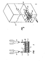
- Figure 1 is a cross-sectional view of the source element according to the present invention
- Figure 2 is an isometric view of the source element nested in insulation blocks, one block removed, also showing electrical connection.
- the present invention is based on the premise that the relatively poor emissivity characteristics of refractory materials at high temperature can be sufficiently overcome by the inclusion of a radiation cavity through which an apparent emissivity approaching that of a blackbody can be realized at all wavelengths of interest. Secondly, the efficiency of a source can greatly be increased by thermally insulating all surfaces of the heated source element other than the radiation cavity, thus eliminating the primary sources of power loss at high temperatures, radiation and convection.
- the source element generally designated 15 consists of a circdlar ceramic rod 2 having furnace wire 1 radially wound about the length of its outer diameter. To maintain even heating distribution from the wire and assure that no windings are shorted together, furnace wire 1 is wound in equally spaced grooves 3 machined or cast about the outer diameter of the ceramic rod 2.. A radiation cavity 4 is machined or cast into one end of the ceramic rod 2 along the central axis of the rod and concentric to the windings 1. The radiation cavity 4 is a drilled blind hole. In operation, the furnace wire 1 is electrically connected to a power source which provides for the heating of the 4 windings 1 and consequently the heating of the ceramic rod 2.
- the exposed ends of the ceramic rod 2 will be somewhat cooler than its mid-section when heated.
- the length of the cavity 4 is chosen such that its bottom remains within the uniformly heated length of the ceramic rod 2.
- the opening of the cavity 4 has machined therein a frusto conical shoulder 11, the intersection of the shoulder 11 and the walls of the cavity 4 being within the uniformly heated length of the ceramic rod 2, said intersection also providing the mouth of the cavity 4.
- the angle of the shoulder 11 is selected not to significantly interfere with the radiant flux eminating from the cavity 4.
- Suitable materials for the ceramic rod 2 include but are not limited to high temperature metallic oxide refractories, such as alumina, beryillia, magnesium oxide, and zirconia, all having melting points in excess of 2250 degrees K, and all stable at high temperatures in air.
- Suitable materials for the furnace wire 1 include but are not limited to platinum, rhodium, iridium, and alloys thereof. Pure platinum can be employed up to temperatures of about 1950 degrees K, alloys of platinum and rhodium allow winding temperatures near 2100 degrees K. Pure rhodium and pure iridium and their alloys can be used at even higher temperatures. They are less ductile and harder to wind, however.
- the free ends of the wound furnace wire 1 also serve as electrical leads 7 and 10 which emanate from the' ceramic core 2.
- Each free end is preferably cut to approximately twice the desired length and then doubled over on itself and twisted. The twisting reduces the electrical resistance of each lead such that the lead temperatures will be substantially cooler than the windings. This measure provides greater protection and greater life for the leads as will become apparent.
- Spade connectors 8 and 9 are crimped and soldered over the folded ends of each lead 7 and 10, respectively, thus providing a means for easy connection and disconnection of the source element 15 from its power source, not shown.
- the spade connectors are chosen to allow low terminal resistance when connected. Such connectors are well known and will not described herein.
- the grooves 3 in the ceramic rod 2 are preferably arranged such that the outer diameter of the winding coil 1 is less than the outer diameter of the ceramic rod 2.
- a high purity refractory cement 6 is trowelled in the annulus formed between these two diameters, and surrounding the exposed surface of each winding 1.
- This winding encapsulation serves a dual purpose. First it protects the windings from scratches and other surface imperfections which lead to premature winding failure. Second, the encapsulation retards evaporation of the furnace wire at high temperatures, and hence prolongs the life of the windings. Both the ceramic rod 2 and the refractory cement 6 should be selected from materials of highest purity.
- a preferred refactory cement 6 consists of slurry of powdered ceramic in deionized water. Once trowelled and water removed, the powdered ceramic is sintered at high temperature to a hard, well-bonded encapsulant.
- a high purity alumina marketed as EA 139 by Norton Company, Worcester, Massachusetts.
- the thus trowelled and sintered surface of refractory cement 6 usually does not form an easily smoothed or even surface, important for proper alignment of the source when assembled into an instrument.
- a thin walled ceramic sleeve 5 is slid over the outer diameter of the ceramic rod 2 prior to the sintering of the refractory cement 6.
- the ceramic sleeve 5 is preferably made of the same refractory material as the ceramic rod 2.
- the inner diameter of the ceramic sleeve 5 is nominally that of the outer diameter of the ceramic rod 2 to maintain concentricity between the central axis of the cavity 4 and the outer diameter of the ceramic sleeve 5.
- the leads 7 and 10 are aligned to be parallel and lie in a single plane which bisects the source along its central axis.
- the ends of each lead 12 and 13 are cut such that the leads 7 and 10 do not short to the adjacent windings 1 yet the ends are well within the outer diameter of the ceramic sleeve 5.
- the sleeve is positioned over the ceramic rod 2 and windings 1 while the refractory cement 6 is still wet.
- the slot in the ceramic sleeve 5 is also filled with cement and trowelled to meet the outer diameter of the sleeve while fully encapsulating the lead ends 12 and 13. All excess cement is removed prior to sintering. Sintering can be accomplished by furnace heating or simply by heating the source through its own windings. In either case the rate of the temperature rise during sintering must be carefully controlled to prevent stress cracking of the unsintered brittle ceramic powder.
- the depth of the radiation cavity, and hence the length of the source element 15, can be quite small and still produce high apparent emissivities for materials having relatively low normal spectral emissivities.
- zirconia a material having a melting point of 3250 degrees K, has an emissivity of approximately 0.15 at high temperatures at 3 micron wave length.
- the apparent emissivity of zirconia at 3 micron can be raised to approximately 0.85 through a cylindrical cavity measuring 1.5 mm diameter by only 10 mm deep.
- wire gauge for the source element windings should be based on electrical resistance, cost, energy consumption, and longevity.
- life of furnace wire is proportional to its cross-sectional area, and decreases with increasing temperature and power loading.
- winding wire should not be subjected to over twelve watts per cm2 of wire surface area; four or less watts per cm2 is a preferred operating point for maximum longevity.
- 27 gauge wire will provide adequate life at relatively low cost.
- the above-described source element 15 comprises the renewable entity of the source apparatus. Since the only usable energy emitted by the source element is through the radiation cavity 4 all external surfaces of the source element are preferably insulated from energy loss to limit heat exchange of the source element with its environment, e.g., a spectrophotometer, and to minimize the power required to heat furnace windings 1, thus prolonging the life of the source element.
- the preferred method to insulate the source element 15, shown in Figure 2 also serves to nest the source element for easy replacement and to align the axis of the radiation cavity 4 with the adjoining optics of the host instrument.
- FIG 2 is an isometric view of a source assembly according to this invention.
- the source element 15 is nested between two adjoining insulation blocks, 16 and 17, composed of refractory materials and having very low thermal conductivity.
- Ceramic fibre insulation is particularly suitable for this application, a good example being an alumina fibre block marketed as WRP-XA by Refractory Products Company, Elgin, Illinois.
- Each insulating block has machined on its mating surfaces the half contour of the source element 15, i.e., half cylinder recesses to captivate the source element body and grooves to captivate its leads 7 and 10.
- the contours are precisely dimensioned such that when the assembly of the insulating blocks 16 and 17 is secured into its host instrument, e.g., a spectrophotometer, the nested source element 15 will properly align with the optics of the host instrument.
- Adjoining the half cylinder recesses in the blocks 16 and 17 are half frusto conic recesses 18 and 19, respectively.
- the recesses 18 and 19 will form a frusto conical extension of the frusto conical opening 11 at the cavity end of source element 15. In this manner, the insulating blocks 16 and 17 will not significantly interfere with radiation emanating from the cavity 4 in the source element 15.
- the half cylinders and half frusto cones can readily be machined by drilling and countersinking into the intersection of insulating blocks 16 and 17,'while clamped together.
- a terminal block 26 made of ceramic material such as alumina, or other electrical insulation material, is made to fit and is secured into a rectangular section of the insulating block 16 at one end directly adjacent to the source element 15 and in line with its electrical leads 7 and 10.
- Two rectangular solid blocks of metal, preferably copper or brass, are secured and separated by rectangular grooves machined into the terminal block 26. Said metal blocks form electrical terminal connectors 22 and 23.
- the spade connectors 8 and 9 of the sample element 15 are secured to the terminal connectors 22 and 23, respectively, through fastening screws 20 and 21, respectively, threaded into the terminal connectors.
- Power supply electrical leads 24 and 25 are inserted through drilled holes in the terminal connectors 22 and 23, respectively, and soldered in place.
- the power supply leads 24 and 25 are also connected to the power supply, not shown, which controls the amount of electrical power which flows across the source element windings.
- the source element 15 can be easily removed and replaced with the simple nesting and terminal connection techniques described above.
- the insulating block 16 is preferably anchored to the host instrument in proper alignment to its optics while the insulating block 17 is clamped to the insulating block 16 through removable bolts (not shown) passing through both blocks, or other suitable means.
- the insulating block 17 is simply unclamped from the insulation block 16, the fastening screws 20 and 21 are loosened and the expired source element is removed; the new source element 15 is then nested in the contoured recesses of the insulating block 16, sliding the spade connectors 8 and 9 under the fastening screws 20 and 21, respectively, and tightening same; the recessed contours of the insulating block 17 are then oriented over the exposed. surfaces of the nested source element 15 and the insulating blocks 16 and 17 reclamped as previously described.
- electric current from the controlling power supply is caused to pass through the leads 7 and 10 and windings 1 in the source element 15, heating the windings in proportion to the product of the current squared and electrical resistance of the windings and to the thermal resistance of the insulating blocks 16 and 17.
- the hot windings uniformly heat the radiation cavity 4 such that radiation approaching blackbody radiation is emitted from its aperture. As the windings rise in temperature, so does its electrical resistance.
- the electrical resistance forms an acceptable form of feedback for controlling the source temperature at the controlling power supply.
- the insulating blocks 16 and 17 restrict the flow of heat from the outer surfaces of the source element 15 from dissipating into and hence heating the host instrument.
- a series of eighteen radial grooves were equally spaced along the length of the alumina rod'symmetrical to the ends, and measured 2.62 mm inner diameter for seventeen grooves, 3.30 mm inner diameter for the eighteenth groove, and all having a 3.81 mm outer diameter.
- the eighteenth groove was located over the countersink of the radiation cavity.
- Each groove was 0.406 mm in width and the spacing was 0.71 mm, and comprised grooves 3 of the source element 15.
- a 27 gauge furnace wire composed of an alloy of 20% rhodium -- 80% platinum, manufactured by Englehard Industries, Carteret, New Jersey, was tightly wound in the eighteen grooves leaving 90 mm free length at each end.
- a refractory cement 6 comprising a 99% purity alumina powder manufactured as EA 139 by Norton Company, Worcester, Mass., admixed with deionized water to form a mortar was trowelled over all windings and grooves to a diameter of at least 4.75 mm about the alumina rod 2. While the cement was still wet the above described alumina ceramic sleeve 5 was slid over the cement and rod as described previously. With all excess cement removed, the thus formed source element was allowed to dry at room temperature for one hour..
- the insulating blocks 16 and 17 were cut from blocks of alumina fibre insulation marketed as WRP- A 5 by Refractory Products, Elgin, Illinois. This material has a thermal conductivity of approximately 2.6 X 10⁻⁴ cal/cm sec degrees C at 1025 degrees K. Each block measured 64.8 mm in length, 43.2 mm front to back and 35.7 mm high. Nesting contours for the source element 15 were machined into both'blocks ' to allow the cavity end of the source element to be located 8.1 mm from the front face of each insulating block and on a central line along their length.
- the above described source element was nested in the insulating blocks and connected to a power source for self-sintering.
- the source element temperature was raised slowly and uniformly to 1875 degrees K over a period of 6.5 hours and held there for 30 minutes. At these temperatures the alumina powder sintered rendering the source element strong and its inner windings well sealed.
- the color temperature of the source cavity was measured with a Model No. 95 pyrometer manufactured by Pyrometer Instrument Company, Northvale, New Jersey.
- the 1.57 mm diameter X 7.6 mm deep radiation cavity in the alumina source element of this example provides apparent emissivities exceeding 0.95 at all wavelengths between 2 and 20 micron wavelength and averaging in excess of 0.99 over the same range. This compares to normal spectral emissivities as low as 0.4 and averaging less tha 0.78 over the same range for a plain alumina surface radiating at the same temperature.
- the power requirement for the nested source element of this invention has been measured at 22 watts for 1700 degrees K and 31 watts for 2000 degrees K cavity color temperature. This compares to 60 watts for a 3.18 mm diameter X 25 mm long Nernst glower operating at 2000 degrees K.
- the source element of this example has operated continuously at 1700 degrees K in excess of 1000 hours without failure.
- the source element of this invention can provide for both greater infrared flux at all wavelengths and greater energy efficiency than prior art spectrophotometric sources.
Landscapes
- Physics & Mathematics (AREA)
- Spectroscopy & Molecular Physics (AREA)
- General Physics & Mathematics (AREA)
- Resistance Heating (AREA)
- Spectrometry And Color Measurement (AREA)
Applications Claiming Priority (2)
| Application Number | Priority Date | Filing Date | Title |
|---|---|---|---|
| US06/434,817 US4499382A (en) | 1982-10-18 | 1982-10-18 | Infrared source element |
| US434817 | 1999-11-05 |
Publications (3)
| Publication Number | Publication Date |
|---|---|
| EP0106431A2 true EP0106431A2 (de) | 1984-04-25 |
| EP0106431A3 EP0106431A3 (en) | 1984-12-05 |
| EP0106431B1 EP0106431B1 (de) | 1987-10-07 |
Family
ID=23725823
Family Applications (1)
| Application Number | Title | Priority Date | Filing Date |
|---|---|---|---|
| EP83303304A Expired EP0106431B1 (de) | 1982-10-18 | 1983-06-08 | Quelle für Infrarotstrahlung |
Country Status (4)
| Country | Link |
|---|---|
| US (1) | US4499382A (de) |
| EP (1) | EP0106431B1 (de) |
| JP (1) | JPS5990021A (de) |
| DE (1) | DE3374026D1 (de) |
Cited By (5)
| Publication number | Priority date | Publication date | Assignee | Title |
|---|---|---|---|---|
| EP0577261A3 (en) * | 1992-07-01 | 1994-06-01 | Nicolet Instrument Corp | High efficiency infrared source |
| EP0692702A1 (de) * | 1994-07-11 | 1996-01-17 | Instrumentarium Corporation | Strahlungsquelle für Infrarot-Gasanalysator und Verfahren zur Erzeugung von Infrarotstrahlung |
| EP0713075A1 (de) * | 1994-11-18 | 1996-05-22 | Hughes Aircraft Company | Thermische Justierungsreferenzquelle |
| DE19848120A1 (de) * | 1998-10-20 | 2000-05-18 | Abb Patent Gmbh | Einrichtung zur Messung der Strahlungsabsorption von Gasen |
| US8610067B2 (en) | 2011-08-25 | 2013-12-17 | Innovative Sensor Technology Ist Ag | Radiation source |
Families Citing this family (7)
| Publication number | Priority date | Publication date | Assignee | Title |
|---|---|---|---|---|
| JPH072211B2 (ja) * | 1988-08-03 | 1995-01-18 | 博 中井 | 遠赤外線放射体の製造方法 |
| US5003184A (en) * | 1989-08-25 | 1991-03-26 | Mobay Corporation | Low temperature infrared source |
| US5030837A (en) * | 1989-09-13 | 1991-07-09 | Hughes Aircraft Company | Thermal beacon assembly |
| US5247185A (en) * | 1991-10-28 | 1993-09-21 | Critikon, Inc. | Regulated infrared source |
| FI107963B (fi) * | 1995-06-20 | 2001-10-31 | Instrumentarium Oy | Infrapunasäteilijä |
| US5939726A (en) * | 1997-12-11 | 1999-08-17 | Cal-Sensors, Inc. | Infrared radiation source |
| US8975604B2 (en) * | 2009-09-18 | 2015-03-10 | Thermo Electron Scientific Instruments Llc | Emissivity enhanced mid IR source |
Family Cites Families (10)
| Publication number | Priority date | Publication date | Assignee | Title |
|---|---|---|---|---|
| US2280977A (en) * | 1939-02-10 | 1942-04-28 | Westinghouse Electric & Mfg Co | High temperature heating unit and method of making same |
| US3138697A (en) * | 1962-10-16 | 1964-06-23 | Barnes Eng Co | Black body radiation sources |
| US3602693A (en) * | 1969-11-20 | 1971-08-31 | Sylvania Electric Prod | Infrared radiation source |
| US3841920A (en) * | 1971-07-06 | 1974-10-15 | Block Engineering | Method of manufacturing an infrared radiation source |
| BE790954A (fr) * | 1971-12-23 | 1973-05-03 | Schlumberger Compteurs | Emetteur de rayonnement infrarouge |
| US4084096A (en) * | 1977-02-14 | 1978-04-11 | Edwards Miles L | Electrically activated infrared source |
| JPS53133691U (de) * | 1977-03-28 | 1978-10-23 | ||
| US4317042A (en) * | 1980-06-26 | 1982-02-23 | Bartell Frederick O | Blackbody simulator with uniform emissivity |
| JPS5754825A (en) * | 1980-09-19 | 1982-04-01 | Yamatake Honeywell Co Ltd | Light source apparatus for infrared ray analyzer |
| JPH0233148Y2 (de) * | 1981-01-30 | 1990-09-06 |
-
1982
- 1982-10-18 US US06/434,817 patent/US4499382A/en not_active Expired - Lifetime
-
1983
- 1983-06-08 DE DE8383303304T patent/DE3374026D1/de not_active Expired
- 1983-06-08 EP EP83303304A patent/EP0106431B1/de not_active Expired
- 1983-10-05 JP JP58186660A patent/JPS5990021A/ja active Granted
Cited By (6)
| Publication number | Priority date | Publication date | Assignee | Title |
|---|---|---|---|---|
| EP0577261A3 (en) * | 1992-07-01 | 1994-06-01 | Nicolet Instrument Corp | High efficiency infrared source |
| EP0692702A1 (de) * | 1994-07-11 | 1996-01-17 | Instrumentarium Corporation | Strahlungsquelle für Infrarot-Gasanalysator und Verfahren zur Erzeugung von Infrarotstrahlung |
| EP0713075A1 (de) * | 1994-11-18 | 1996-05-22 | Hughes Aircraft Company | Thermische Justierungsreferenzquelle |
| DE19848120A1 (de) * | 1998-10-20 | 2000-05-18 | Abb Patent Gmbh | Einrichtung zur Messung der Strahlungsabsorption von Gasen |
| DE19848120C2 (de) * | 1998-10-20 | 2001-09-27 | Abb Patent Gmbh | Einrichtung zur Messung der Strahlungsabsorption von Gasen |
| US8610067B2 (en) | 2011-08-25 | 2013-12-17 | Innovative Sensor Technology Ist Ag | Radiation source |
Also Published As
| Publication number | Publication date |
|---|---|
| EP0106431A3 (en) | 1984-12-05 |
| JPS5990021A (ja) | 1984-05-24 |
| JPH0564285B2 (de) | 1993-09-14 |
| EP0106431B1 (de) | 1987-10-07 |
| DE3374026D1 (en) | 1987-11-12 |
| US4499382A (en) | 1985-02-12 |
Similar Documents
| Publication | Publication Date | Title |
|---|---|---|
| EP0106431B1 (de) | Quelle für Infrarotstrahlung | |
| US5296686A (en) | Heating element | |
| TWI649860B (zh) | 紅外線發射器 | |
| EP2115372B1 (de) | Lampe für eine kammer für schnelles thermisches verfahren | |
| US5247185A (en) | Regulated infrared source | |
| US4774396A (en) | Infrared generator | |
| CN104535224B (zh) | 一种高温热电偶检定炉用加热体 | |
| US4241292A (en) | Resistive heater | |
| US3205343A (en) | Blackbody source | |
| Lapworth et al. | A black-body source of radiation covering a wavelength range from the ultraviolet to the infrared | |
| US6018216A (en) | Multielement selective emitter | |
| Sapritsky et al. | Blackbody sources for the range 100 K to 3500 K for precision measurements in radiometry and radiation thermometry | |
| US5747820A (en) | Infrared radiation source for a gas analyzer and method for generating infrared radiation | |
| Glaser | Imaging‐Furnace Developments for High‐Temperature Research | |
| US4214117A (en) | Furnace heated by radiation | |
| JPH05343170A (ja) | 光ファイバ加工用小型電気炉 | |
| US20040062287A1 (en) | Electric resistance furnace | |
| US8975604B2 (en) | Emissivity enhanced mid IR source | |
| US20030095796A1 (en) | Apparatus for the uniform heating of substrates or of surfaces, and the use thereof | |
| US20030214258A1 (en) | Selective emitter with electrical stabilization and switching | |
| RU2148801C1 (ru) | Модель черного тела | |
| JPS6188481A (ja) | 赤外線放射体 | |
| US20040084441A1 (en) | Resistance-heating element, and electric resistance furnace using the same | |
| JPH0143621Y2 (de) | ||
| CN1056746A (zh) | 双球腔实用标准黑体 |
Legal Events
| Date | Code | Title | Description |
|---|---|---|---|
| PUAI | Public reference made under article 153(3) epc to a published international application that has entered the european phase |
Free format text: ORIGINAL CODE: 0009012 |
|
| 17P | Request for examination filed |
Effective date: 19830613 |
|
| AK | Designated contracting states |
Designated state(s): DE FR GB |
|
| PUAL | Search report despatched |
Free format text: ORIGINAL CODE: 0009013 |
|
| AK | Designated contracting states |
Designated state(s): DE FR GB |
|
| 17Q | First examination report despatched |
Effective date: 19860416 |
|
| GRAA | (expected) grant |
Free format text: ORIGINAL CODE: 0009210 |
|
| AK | Designated contracting states |
Kind code of ref document: B1 Designated state(s): DE FR GB |
|
| REF | Corresponds to: |
Ref document number: 3374026 Country of ref document: DE Date of ref document: 19871112 |
|
| ET | Fr: translation filed | ||
| PLBE | No opposition filed within time limit |
Free format text: ORIGINAL CODE: 0009261 |
|
| STAA | Information on the status of an ep patent application or granted ep patent |
Free format text: STATUS: NO OPPOSITION FILED WITHIN TIME LIMIT |
|
| 26N | No opposition filed | ||
| PGFP | Annual fee paid to national office [announced via postgrant information from national office to epo] |
Ref country code: FR Payment date: 19960515 Year of fee payment: 14 |
|
| PGFP | Annual fee paid to national office [announced via postgrant information from national office to epo] |
Ref country code: DE Payment date: 19960528 Year of fee payment: 14 |
|
| PGFP | Annual fee paid to national office [announced via postgrant information from national office to epo] |
Ref country code: GB Payment date: 19960529 Year of fee payment: 14 |
|
| PG25 | Lapsed in a contracting state [announced via postgrant information from national office to epo] |
Ref country code: GB Free format text: LAPSE BECAUSE OF NON-PAYMENT OF DUE FEES Effective date: 19970608 |
|
| GBPC | Gb: european patent ceased through non-payment of renewal fee |
Effective date: 19970608 |
|
| PG25 | Lapsed in a contracting state [announced via postgrant information from national office to epo] |
Ref country code: FR Free format text: LAPSE BECAUSE OF NON-PAYMENT OF DUE FEES Effective date: 19980227 |
|
| PG25 | Lapsed in a contracting state [announced via postgrant information from national office to epo] |
Ref country code: DE Free format text: LAPSE BECAUSE OF NON-PAYMENT OF DUE FEES Effective date: 19980303 |
|
| REG | Reference to a national code |
Ref country code: FR Ref legal event code: ST |
|
| REG | Reference to a national code |
Ref country code: FR Ref legal event code: ST |