EP0106079A2 - Überspannungsschutz für Signalübertragungssysteme - Google Patents
Überspannungsschutz für Signalübertragungssysteme Download PDFInfo
- Publication number
- EP0106079A2 EP0106079A2 EP83108377A EP83108377A EP0106079A2 EP 0106079 A2 EP0106079 A2 EP 0106079A2 EP 83108377 A EP83108377 A EP 83108377A EP 83108377 A EP83108377 A EP 83108377A EP 0106079 A2 EP0106079 A2 EP 0106079A2
- Authority
- EP
- European Patent Office
- Prior art keywords
- amplifier
- surge
- cathode
- bridge
- anode
- Prior art date
- Legal status (The legal status is an assumption and is not a legal conclusion. Google has not performed a legal analysis and makes no representation as to the accuracy of the status listed.)
- Granted
Links
- 230000008054 signal transmission Effects 0.000 title claims description 9
- 239000004020 conductor Substances 0.000 claims abstract description 26
- 230000005540 biological transmission Effects 0.000 claims abstract description 24
- 238000000605 extraction Methods 0.000 claims description 10
- 238000004804 winding Methods 0.000 description 8
- 238000010586 diagram Methods 0.000 description 3
- OKTJSMMVPCPJKN-UHFFFAOYSA-N Carbon Chemical compound [C] OKTJSMMVPCPJKN-UHFFFAOYSA-N 0.000 description 2
- 229910052799 carbon Inorganic materials 0.000 description 2
- 230000002457 bidirectional effect Effects 0.000 description 1
- 239000000969 carrier Substances 0.000 description 1
- 230000008878 coupling Effects 0.000 description 1
- 238000010168 coupling process Methods 0.000 description 1
- 238000005859 coupling reaction Methods 0.000 description 1
- 230000001419 dependent effect Effects 0.000 description 1
- 230000001066 destructive effect Effects 0.000 description 1
- 230000006866 deterioration Effects 0.000 description 1
- 231100001261 hazardous Toxicity 0.000 description 1
- 238000013021 overheating Methods 0.000 description 1
- 239000004065 semiconductor Substances 0.000 description 1
- 230000001052 transient effect Effects 0.000 description 1
Images

Classifications
-
- H—ELECTRICITY
- H04—ELECTRIC COMMUNICATION TECHNIQUE
- H04M—TELEPHONIC COMMUNICATION
- H04M1/00—Substation equipment, e.g. for use by subscribers
- H04M1/738—Interface circuits for coupling substations to external telephone lines
- H04M1/74—Interface circuits for coupling substations to external telephone lines with means for reducing interference; with means for reducing effects due to line faults
- H04M1/745—Protection devices or circuits for voltages surges on the line
-
- H—ELECTRICITY
- H02—GENERATION; CONVERSION OR DISTRIBUTION OF ELECTRIC POWER
- H02H—EMERGENCY PROTECTIVE CIRCUIT ARRANGEMENTS
- H02H9/00—Emergency protective circuit arrangements for limiting excess current or voltage without disconnection
- H02H9/04—Emergency protective circuit arrangements for limiting excess current or voltage without disconnection responsive to excess voltage
- H02H9/049—Circuit arrangements for limiting the number of protection devices
-
- H—ELECTRICITY
- H04—ELECTRIC COMMUNICATION TECHNIQUE
- H04B—TRANSMISSION
- H04B3/00—Line transmission systems
-
- H—ELECTRICITY
- H04—ELECTRIC COMMUNICATION TECHNIQUE
- H04B—TRANSMISSION
- H04B3/00—Line transmission systems
- H04B3/02—Details
- H04B3/46—Monitoring; Testing
Definitions
- the invention relates to surge protection for signal transmission systems having a plurality of transmission lines and is particularly applicable to protecting line-powered repeater amplifiers interconnecting telephone lines against damage by hazardous surges on the lines.
- Surges are produced in telephone or other signal transmission lines in various ways. Short duration surges may be produced by lightning discharges in the vicinity of, or directly onto, the transmission line. Longer duration surges may be produced by a neighbouring power transmission line experiencing fault or unbalanced-loading conditions. Line repeater amplifiers interconnecting multi-paired telephone cables in rural areas are particularly vulnerable because such cables are often carried by the same poles that carry power conductors and are also more exposed to lightning.
- surges propagate along the telephone or other signal line and impinge upon the line repeater amplifiers or other equipment terminating the line.
- the destructive effect of the surge is dependent upon both its amptitude and duration, neither of which is predictable. It is usual therefore to design the terminating equipment to withstand surges of a specified level and duration and to provide surge diverters to prevent higher voltages reaching the equipment.
- surge diverters characteristically have a very high impedance until a certain threshold voltage is impressed across them, whereupon they switch or "fire" providing a low impedance path around the equipment to be protected.
- Such secondary protection often is provided at the equipment, for example on the line reater card, and comprises resistors and a solid-state device which will operate many times over a long period without deterioration.
- One known scheme using solid-state devices has a diode bridge with its cathode/anode nodes connected one to each of the line terminals of the equipment to be protected. A series resistor is connected between each such terminal and the associated line conductor.
- a Transzorb Trade Mark
- a transient voltage suppressor characterised by high surge handling capacity and very fast response time, interconnects the other nodes of the bridge.
- the anode of the Transzorb is connected to the anode/anode node of the bridge.
- a differential-mode surge raises the voltage between the line terminals to a predetermined level the Transzorb "fires", providing a low impedance shunt path via the Transzorb and two opposite arms of the bridge.
- the series resistors limit the current through the shunt path to a safe level for the components.
- the Transzorb will not "fire” if a common mode surge raises the voltage of both conductors of a line simultaneously relative to a common bus. Then relatively low voltage, high current surges, for example induced common-mode 60Hz power surges, may overload the series resistors and transformer and/or power extraction device without the threshold voltage being developed across the Transzorb to "fire” it. Also the Transzorb is primarily intended to respond to high amplitude, short duration surges, and it will be appreciated that to upgrade the system would require bulkier components to be accommodated on an already congested repeater card.
- An object of the present invention is to overcome these disadvantages.
- a signal transmission system having a plurality of transmission lines, each line comprising a pair of conductors, includes surge protection means comprising a first diode bridge with its cathode/anode nodes connected to respective conductors of one line, a second diode bridge with its cathode/anode nodes connected to respective conductors of a second line, and a pair of surge diverter devices each connected between the anode/anode node of one diode bridge and the cathode/cathode node of the other diode bridge.
- Each surge diverter device comprises a device which switches from a high impedance state to a low impedance state when a predetermined threshold voltage is impressed across it.
- the two lines interconnected by the protection circuitry are coupled in series by a signal amplifier.
- the two lines interconnected by the protection circuitry are coupled to two different amplifiers connected in opposite directions. Said one line is connected to the input of one amplifier, said second line is connected to the output of the other amplifier.
- power for the or each amplifier may be supplied via the lines.
- Power extraction means then conveniently comprises a Zener diode interconnecting the same lines that are coupled by a surge diverter.
- each Figure shows two repeater amplifiers connected to convey signals in opposite directions.
- Each amplifier is connected in series between two transmission lines.
- each such line will usually comprise two conductors, designated “tip” (T) and “ring” (R), of a shielded multipaired cable.
- T tip
- R ring
- the two repeater amplifiers, together with many similarly connected pairs of amplifiers, would be located at a line repeater station. Several such stations might be provided at discrete locations along the multipaired cable. It should be understood that, although not shown, primary protection in the form of a pair of gas tubes or the like would be provided between each line conductor and a common bus.
- a repeater amplifier 10A interconnects the conductors 11A, 12A of an incoming transmission line with the conductors 13A, 14A of an outgoing line.
- the conductors 11A and 12A are connected via series resistors 15A and 16A, respectively, to opposite ends of a centre tapped primary winding of a transformer 17A.
- the secondary winding of the transformer is coupled to the input of the repeater amplifier 10A.
- a similar transformer 18A is connected to the output of the repeater amplifier 10A and has its centre tapped winding connected via series resistors 19A and 20A, respectively, to the conductors 13A and 14A of the outgoing line.
- the centre taps of the transformers 17A and 18A are connected directly together in well known manner to provide d.c. coupling between the two lines.
- a diode bridge 21A is connected with its cathode/anode nodes one to each end of the centre-tapped winding of input transformer 17A.
- a Transzorb 22A has its anode connected to the anode/anode node 23A of the bridge 21A and its cathode connected to the cathode/cathode node 24A of the bridge.
- a second Transzorb 25A and diode bridge 26A are connected in similar fashion across the centre-tapped winding of the output transformer 18A.
- the second repeater amplifier 10B is arranged to convey signals oppositely to the first repeater amplifier 10A but otherwise is connected to the line conductors 13B, 14B and 11B, 12B by a similar set of series resistors 15B, 16B and 19B, 20B, and input and output transformers 17B and 18B, respectively, and is protected by Transzorbs 22B and 25B connected across diode bridges 22B and 26B, respectively.
- the centre taps of transformers 17B and 18B are not directly interconnected but instead are interconnected by a power-extraction Zener diode 27B which supplies power to both repeater amplifiers 10A and 10B.
- the power is derived from a constant current source fed serially to each line from a main source (not shown) in a well known manner. Usually, one line will be connected to a 130 volt positive source and the other to a 130 volt negative source.
- the Transzorbs 22A, 25A, 22B and 25B are non-conducting and present a relatively high impedance across the corresponding line.
- the Transzorb 22A conducts, providing with the diodes in opposite arms of the bridge 21A a relatively low impedance shunt path across the transformer 17A.
- the resistors 15A and 16A limit the current in this shunt path to a safe value.
- Embodiments of the invention overcome these problems.
- the embodiment shown in Figure 2 differs from the prior art circuit of Figure 1 in that the diode bridges 21 and 26 are connected directly across the corresponding line conductors 11, 12 and 13, 14, respectively. Also the pairs of series resistors 15, 16 and 19, 20, are each connected in series between the corresponding bridge node and the centre-tapped transformer winding. There is no significance to the power extraction Zener diode 27A 'being associated with amplifier 10A rather than amplifier 10B.
- each diverter 30 has its anode connected to the anode/anode node 23 of input bridge 21 and its cathode connected to the cathode/cathode node 32 of output bridge 26.
- Each second diverter, 31, has its anode connected to the anode/anode node 33 of output bridge 26 and its cathode connected to the cathode/cathode node 24 of input bridge 21.
- a high voltage (lightning) surge on any one or pair of conductors of one line will cause one or other of the surge diverters to "fire", shunting the surge past the amplifier to the other line.
- power is fed in known manner from two opposite polarity 130 volt sources, one at each end of the system, towards a central point.
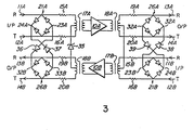
- the embodiment of Figure 3 is different, being a so-called "power-looping" repeater amplifier arrangement in which the input transformer of each amplifier is d.c. coupled to the output transformer of the other amplifier.
- the power extraction diode 35 is connected between the centre taps of input transformer 17A and output transformer 188, respectively, and the centre taps of transformers 18A and 17B are directly interconnected.
- the surge diverters follow the power feed.
- one pair of diverters 36 and 37 interconnect the corresponding nodes of diode bridges 21A and 26B, and a second pair of diverters 38, 39 interconnect diode bridges 21B and 26A.
- the operation of this embodiment is basically the same as that illustrated in Figure 2, except that the surge is now diverted to a different pair of conductors in the same multi-paired cable. It should perhaps be noted that in such a cable the input pairs usually are segregated from the output pairs by a grounded inner divider or sheath.
- surge diverters other than Transzorbs will be required since they must be capable of handling the longer duration power surges with associated relatively long thermal time constants. Nevertheless, the diverters should still have a fast response so as to respond to short rise-time lightning pulses. It should be noted that the d.c. power supply current will persist after the surge has dissipated. Consequently the surge diverter devices should turn off in the presence of this supply. If necessary, additional control circuitry might be provided to turn the device off.
- One device suitable for telephone line repeater protection is presently marketed under the type number LS 5060 by SGS Semiconductor Group and is configured as a triac, having a bidirectional characteristic.
- the device switches or "fires” when the voltage across it exceeds about 60 volts, substantially independently of the surge rise-time.
- the voltage across the device in its "on” state is about 2 volts, allowing it to handle relatively long duration surges without excessive dissipation requirements.
- the device's "holding” current is larger than the d.c. power supply current so that the device will return to its "off” state when the surge dissappears.
- a corresponding unidirectional device effectively a single SCR, will be used since the diode bridges provide polarity steering. It is expected that such a device will "switch" when the voltage across it exceeds about 18 volts, so that, with series resistors of, say, 5.6 ohms, the device will switch when the surge current exceeds about 1 ampere.
- the capacitance across the amplifier must be kept low enough to avoid undesirable feedback.
- An advantage of embodiments of the invention is that the shunt path always includes the capacitance of two of the bridge diodes in series with that of the surge diverter. Therefore these diodes and the diverter itself may each have a relatively high capacitance and corresponding current-carrying capacity.
- the invention comprehends other systems in which transmission lines, such as coaxial cables, are interconnected by surge-sensitive devices such as amplifiers.
Landscapes
- Engineering & Computer Science (AREA)
- Signal Processing (AREA)
- Computer Networks & Wireless Communication (AREA)
- Emergency Protection Circuit Devices (AREA)
- Cable Transmission Systems, Equalization Of Radio And Reduction Of Echo (AREA)
Applications Claiming Priority (2)
| Application Number | Priority Date | Filing Date | Title |
|---|---|---|---|
| CA000412030A CA1186016A (en) | 1982-09-23 | 1982-09-23 | Surge protection for signal transmission systems |
| CA412030 | 1982-09-23 |
Publications (3)
| Publication Number | Publication Date |
|---|---|
| EP0106079A2 true EP0106079A2 (de) | 1984-04-25 |
| EP0106079A3 EP0106079A3 (en) | 1984-05-23 |
| EP0106079B1 EP0106079B1 (de) | 1986-12-30 |
Family
ID=4123649
Family Applications (1)
| Application Number | Title | Priority Date | Filing Date |
|---|---|---|---|
| EP83108377A Expired EP0106079B1 (de) | 1982-09-23 | 1983-08-25 | Überspannungsschutz für Signalübertragungssysteme |
Country Status (5)
| Country | Link |
|---|---|
| US (1) | US4449157A (de) |
| EP (1) | EP0106079B1 (de) |
| JP (1) | JPS5976120A (de) |
| CA (1) | CA1186016A (de) |
| DE (1) | DE3368825D1 (de) |
Cited By (2)
| Publication number | Priority date | Publication date | Assignee | Title |
|---|---|---|---|---|
| GB2258570A (en) * | 1991-08-08 | 1993-02-10 | British Telecomm | Device for protecting high speed communications network from overvoltages |
| CN105552870A (zh) * | 2014-10-27 | 2016-05-04 | 菲尼克斯电气公司 | 一种用于有线数据传输系统数据传送的有源保护电路 |
Families Citing this family (6)
| Publication number | Priority date | Publication date | Assignee | Title |
|---|---|---|---|---|
| JPS637137A (ja) * | 1986-06-26 | 1988-01-13 | 株式会社 昭電 | 過電圧保護回路 |
| JPS63133819A (ja) * | 1986-11-11 | 1988-06-06 | シーメンス、アクチエンゲゼルシヤフト | 自己保護性電力開閉器の回路装置 |
| US4878145A (en) * | 1988-11-21 | 1989-10-31 | Oneac Corporation | Surge/transient protector for a plurality of data lines |
| GB9021222D0 (en) * | 1990-09-28 | 1990-11-14 | Raychem Ltd | Circuit protection device |
| US5493469A (en) * | 1991-01-18 | 1996-02-20 | Mildred A. Lace | Surge protection for data lines |
| US9912149B2 (en) * | 2014-08-06 | 2018-03-06 | Sensomatic Electronics, LLC | Lightning and surge protection for electronic circuits |
Family Cites Families (8)
| Publication number | Priority date | Publication date | Assignee | Title |
|---|---|---|---|---|
| US3152319A (en) * | 1958-10-06 | 1964-10-06 | Epsco Inc | Signal switching system |
| US3633093A (en) * | 1970-07-01 | 1972-01-04 | Honeywell Inc | Amplifier overload protection circuit |
| GB1492153A (en) * | 1976-05-25 | 1977-11-16 | Standard Telephones Cables Ltd | Repeaters |
| US4066918A (en) * | 1976-09-30 | 1978-01-03 | Rca Corporation | Protection circuitry for insulated-gate field-effect transistor (IGFET) circuits |
| US4161008A (en) * | 1978-04-26 | 1979-07-10 | Northern Telecom Limited | Protection circuitry for cable transmission system |
| US4213012A (en) * | 1978-11-03 | 1980-07-15 | General Signal Corporation | Discriminating means for telephone circuits |
| US4389695A (en) * | 1981-02-09 | 1983-06-21 | Carpenter Jr Roy B | Equipment for protecting electronic equipment and personnel against inadvertent occurrence of extended or transient high voltages and method |
| JPS58144531A (ja) * | 1982-02-22 | 1983-08-27 | 日本電信電話株式会社 | 過電圧印加防止回路 |
-
1982
- 1982-09-23 CA CA000412030A patent/CA1186016A/en not_active Expired
- 1982-09-27 US US06/423,609 patent/US4449157A/en not_active Expired - Lifetime
-
1983
- 1983-08-25 DE DE8383108377T patent/DE3368825D1/de not_active Expired
- 1983-08-25 EP EP83108377A patent/EP0106079B1/de not_active Expired
- 1983-09-22 JP JP58174401A patent/JPS5976120A/ja active Pending
Cited By (3)
| Publication number | Priority date | Publication date | Assignee | Title |
|---|---|---|---|---|
| GB2258570A (en) * | 1991-08-08 | 1993-02-10 | British Telecomm | Device for protecting high speed communications network from overvoltages |
| CN105552870A (zh) * | 2014-10-27 | 2016-05-04 | 菲尼克斯电气公司 | 一种用于有线数据传输系统数据传送的有源保护电路 |
| CN105552870B (zh) * | 2014-10-27 | 2018-04-13 | 菲尼克斯电气公司 | 一种用于有线数据传输系统数据传送的有源保护电路 |
Also Published As
| Publication number | Publication date |
|---|---|
| DE3368825D1 (en) | 1987-02-05 |
| EP0106079B1 (de) | 1986-12-30 |
| CA1186016A (en) | 1985-04-23 |
| EP0106079A3 (en) | 1984-05-23 |
| JPS5976120A (ja) | 1984-05-01 |
| US4449157A (en) | 1984-05-15 |
Similar Documents
| Publication | Publication Date | Title |
|---|---|---|
| US4203006A (en) | Direct access coupler | |
| EP0338107B1 (de) | Überspannungs-Schutzschaltung, die mit einem Telefonleitungspaar oder ähnlichen Datenkommunikationsleitungen benutzt wird | |
| US4389695A (en) | Equipment for protecting electronic equipment and personnel against inadvertent occurrence of extended or transient high voltages and method | |
| US7687791B2 (en) | Ethernet data signal transmission apparatus | |
| US4661878A (en) | Overvoltage protection circuit | |
| US5323289A (en) | Lightning protection for field mounted instruments | |
| US5719693A (en) | Power feeding system for an optical transmission system | |
| US4449157A (en) | Surge protection for signal transmission systems | |
| US4161008A (en) | Protection circuitry for cable transmission system | |
| US5570263A (en) | Communications bus surge protector | |
| US4099217A (en) | Protection circuits | |
| US4110570A (en) | Surge protection device for repeater | |
| FI85929C (fi) | Skyddskrets foer skydd av en abonnentkrets mot oeverspaenningar. | |
| US2356296A (en) | Protective system | |
| EP0185777A1 (de) | Sicherheitsschaltung zum Überspannschutz bei Mehrdrahtverbindungen | |
| GB2133939A (en) | An h v d c cable protection system | |
| US4734937A (en) | Telephone installation | |
| US4253131A (en) | Repeater overload circuit | |
| KR102345726B1 (ko) | 다중 접지형 서지 보호장치 | |
| JPH0312029Y2 (de) | ||
| CA1270300A (en) | Safety circuit system for overvoltage protection of multiwire lines | |
| CA2085189A1 (en) | Circuit arrangement for protecting interface circuits against overvoltages | |
| US2037859A (en) | Protective system for cable circuits | |
| US1979256A (en) | Electrical protective system | |
| CA3205062A1 (en) | Protective device for protecting an electrical track-field infrastructure, track-field power supply apparatus and method for limiting potential shifts in an electrical track-field infrastructure |
Legal Events
| Date | Code | Title | Description |
|---|---|---|---|
| PUAI | Public reference made under article 153(3) epc to a published international application that has entered the european phase |
Free format text: ORIGINAL CODE: 0009012 |
|
| PUAL | Search report despatched |
Free format text: ORIGINAL CODE: 0009013 |
|
| AK | Designated contracting states |
Designated state(s): DE FR GB NL SE |
|
| AK | Designated contracting states |
Designated state(s): DE FR GB NL SE |
|
| 17P | Request for examination filed |
Effective date: 19840625 |
|
| GRAA | (expected) grant |
Free format text: ORIGINAL CODE: 0009210 |
|
| AK | Designated contracting states |
Kind code of ref document: B1 Designated state(s): DE FR GB NL SE |
|
| ET | Fr: translation filed | ||
| REF | Corresponds to: |
Ref document number: 3368825 Country of ref document: DE Date of ref document: 19870205 |
|
| PLBE | No opposition filed within time limit |
Free format text: ORIGINAL CODE: 0009261 |
|
| STAA | Information on the status of an ep patent application or granted ep patent |
Free format text: STATUS: NO OPPOSITION FILED WITHIN TIME LIMIT |
|
| 26N | No opposition filed | ||
| PGFP | Annual fee paid to national office [announced via postgrant information from national office to epo] |
Ref country code: SE Payment date: 19900807 Year of fee payment: 8 Ref country code: FR Payment date: 19900807 Year of fee payment: 8 |
|
| PGFP | Annual fee paid to national office [announced via postgrant information from national office to epo] |
Ref country code: GB Payment date: 19900813 Year of fee payment: 8 |
|
| PGFP | Annual fee paid to national office [announced via postgrant information from national office to epo] |
Ref country code: NL Payment date: 19900831 Year of fee payment: 8 |
|
| PGFP | Annual fee paid to national office [announced via postgrant information from national office to epo] |
Ref country code: DE Payment date: 19900927 Year of fee payment: 8 |
|
| PG25 | Lapsed in a contracting state [announced via postgrant information from national office to epo] |
Ref country code: GB Effective date: 19910825 |
|
| PG25 | Lapsed in a contracting state [announced via postgrant information from national office to epo] |
Ref country code: SE Effective date: 19910826 |
|
| PG25 | Lapsed in a contracting state [announced via postgrant information from national office to epo] |
Ref country code: NL Effective date: 19920301 |
|
| NLV4 | Nl: lapsed or anulled due to non-payment of the annual fee | ||
| GBPC | Gb: european patent ceased through non-payment of renewal fee | ||
| PG25 | Lapsed in a contracting state [announced via postgrant information from national office to epo] |
Ref country code: FR Effective date: 19920430 |
|
| PG25 | Lapsed in a contracting state [announced via postgrant information from national office to epo] |
Ref country code: DE Effective date: 19920501 |
|
| REG | Reference to a national code |
Ref country code: FR Ref legal event code: ST |
|
| EUG | Se: european patent has lapsed |
Ref document number: 83108377.9 Effective date: 19920306 |