EP0106021A2 - Ferrous product having an alloy coating thereon of aluminium-zinc-magnesium-silicon, and method - Google Patents
Ferrous product having an alloy coating thereon of aluminium-zinc-magnesium-silicon, and method Download PDFInfo
- Publication number
- EP0106021A2 EP0106021A2 EP83106105A EP83106105A EP0106021A2 EP 0106021 A2 EP0106021 A2 EP 0106021A2 EP 83106105 A EP83106105 A EP 83106105A EP 83106105 A EP83106105 A EP 83106105A EP 0106021 A2 EP0106021 A2 EP 0106021A2
- Authority
- EP
- European Patent Office
- Prior art keywords
- coating
- alloy
- overlay
- zinc
- silicon
- Prior art date
- Legal status (The legal status is an assumption and is not a legal conclusion. Google has not performed a legal analysis and makes no representation as to the accuracy of the status listed.)
- Granted
Links
- 238000000576 coating method Methods 0.000 title claims abstract description 161
- 239000011248 coating agent Substances 0.000 title claims abstract description 121
- 229910045601 alloy Inorganic materials 0.000 title claims abstract description 68
- 239000000956 alloy Substances 0.000 title claims abstract description 68
- CWYNVVGOOAEACU-UHFFFAOYSA-N Fe2+ Chemical compound [Fe+2] CWYNVVGOOAEACU-UHFFFAOYSA-N 0.000 title claims abstract description 44
- 238000000034 method Methods 0.000 title claims description 10
- -1 aluminium-zinc-magnesium-silicon Chemical compound 0.000 title description 3
- 239000011701 zinc Substances 0.000 claims abstract description 70
- 229910052710 silicon Inorganic materials 0.000 claims abstract description 58
- 238000005260 corrosion Methods 0.000 claims abstract description 56
- 230000007797 corrosion Effects 0.000 claims abstract description 56
- 239000011777 magnesium Substances 0.000 claims abstract description 47
- 229910052782 aluminium Inorganic materials 0.000 claims abstract description 44
- 229910052749 magnesium Inorganic materials 0.000 claims abstract description 44
- 239000010703 silicon Substances 0.000 claims abstract description 38
- XUIMIQQOPSSXEZ-UHFFFAOYSA-N Silicon Chemical compound [Si] XUIMIQQOPSSXEZ-UHFFFAOYSA-N 0.000 claims abstract description 37
- 229910052725 zinc Inorganic materials 0.000 claims abstract description 37
- XAGFODPZIPBFFR-UHFFFAOYSA-N aluminium Chemical compound [Al] XAGFODPZIPBFFR-UHFFFAOYSA-N 0.000 claims abstract description 34
- HCHKCACWOHOZIP-UHFFFAOYSA-N Zinc Chemical compound [Zn] HCHKCACWOHOZIP-UHFFFAOYSA-N 0.000 claims abstract description 33
- FYYHWMGAXLPEAU-UHFFFAOYSA-N Magnesium Chemical compound [Mg] FYYHWMGAXLPEAU-UHFFFAOYSA-N 0.000 claims abstract description 27
- 210000001787 dendrite Anatomy 0.000 claims abstract description 17
- 239000000203 mixture Substances 0.000 claims abstract description 12
- 230000001464 adherent effect Effects 0.000 claims abstract description 7
- 239000001995 intermetallic alloy Substances 0.000 claims abstract description 7
- 150000003839 salts Chemical class 0.000 claims description 13
- 229910007981 Si-Mg Inorganic materials 0.000 claims description 8
- 229910008316 Si—Mg Inorganic materials 0.000 claims description 8
- 238000001816 cooling Methods 0.000 claims description 8
- 229910019752 Mg2Si Inorganic materials 0.000 claims description 7
- VYPSYNLAJGMNEJ-UHFFFAOYSA-N silicon dioxide Inorganic materials O=[Si]=O VYPSYNLAJGMNEJ-UHFFFAOYSA-N 0.000 claims description 5
- 238000007711 solidification Methods 0.000 claims description 5
- 230000008023 solidification Effects 0.000 claims description 5
- 238000004519 manufacturing process Methods 0.000 claims description 4
- XLYOFNOQVPJJNP-UHFFFAOYSA-N water Substances O XLYOFNOQVPJJNP-UHFFFAOYSA-N 0.000 claims description 4
- 229910001209 Low-carbon steel Inorganic materials 0.000 claims description 3
- 229910017708 MgZn2 Inorganic materials 0.000 claims description 3
- 229910052681 coesite Inorganic materials 0.000 claims description 3
- 229910052906 cristobalite Inorganic materials 0.000 claims description 3
- 229910052682 stishovite Inorganic materials 0.000 claims description 3
- 229910052905 tridymite Inorganic materials 0.000 claims description 3
- 239000000758 substrate Substances 0.000 abstract description 16
- 229910052751 metal Inorganic materials 0.000 abstract description 12
- 239000002184 metal Substances 0.000 abstract description 12
- 238000003618 dip coating Methods 0.000 abstract description 10
- 239000000047 product Substances 0.000 description 29
- 229910000831 Steel Inorganic materials 0.000 description 25
- 239000010959 steel Substances 0.000 description 25
- 238000012360 testing method Methods 0.000 description 16
- 239000007921 spray Substances 0.000 description 10
- 229910018137 Al-Zn Inorganic materials 0.000 description 9
- 229910018573 Al—Zn Inorganic materials 0.000 description 9
- 239000000470 constituent Substances 0.000 description 8
- 230000000694 effects Effects 0.000 description 7
- 239000012298 atmosphere Substances 0.000 description 6
- 239000008199 coating composition Substances 0.000 description 6
- 230000004580 weight loss Effects 0.000 description 6
- 229910019064 Mg-Si Inorganic materials 0.000 description 5
- 229910019406 Mg—Si Inorganic materials 0.000 description 5
- 230000004888 barrier function Effects 0.000 description 5
- 238000011835 investigation Methods 0.000 description 5
- 230000007246 mechanism Effects 0.000 description 5
- 150000002739 metals Chemical class 0.000 description 5
- 229910001297 Zn alloy Inorganic materials 0.000 description 4
- 238000007792 addition Methods 0.000 description 4
- 238000012545 processing Methods 0.000 description 4
- 229910000975 Carbon steel Inorganic materials 0.000 description 3
- 238000004140 cleaning Methods 0.000 description 3
- XEEYBQQBJWHFJM-UHFFFAOYSA-N iron Substances [Fe] XEEYBQQBJWHFJM-UHFFFAOYSA-N 0.000 description 3
- 230000008018 melting Effects 0.000 description 3
- 238000002844 melting Methods 0.000 description 3
- IJGRMHOSHXDMSA-UHFFFAOYSA-N nitrogen Substances N#N IJGRMHOSHXDMSA-UHFFFAOYSA-N 0.000 description 3
- 229910000838 Al alloy Inorganic materials 0.000 description 2
- FJMNNXLGOUYVHO-UHFFFAOYSA-N aluminum zinc Chemical compound [Al].[Zn] FJMNNXLGOUYVHO-UHFFFAOYSA-N 0.000 description 2
- 230000009286 beneficial effect Effects 0.000 description 2
- 229910052804 chromium Inorganic materials 0.000 description 2
- 239000011651 chromium Substances 0.000 description 2
- 230000001627 detrimental effect Effects 0.000 description 2
- 238000007598 dipping method Methods 0.000 description 2
- 239000004519 grease Substances 0.000 description 2
- 229910000765 intermetallic Inorganic materials 0.000 description 2
- 238000011005 laboratory method Methods 0.000 description 2
- 239000011159 matrix material Substances 0.000 description 2
- 229910052757 nitrogen Inorganic materials 0.000 description 2
- 230000009022 nonlinear effect Effects 0.000 description 2
- 230000003647 oxidation Effects 0.000 description 2
- 238000007254 oxidation reaction Methods 0.000 description 2
- 239000002245 particle Substances 0.000 description 2
- 239000000377 silicon dioxide Substances 0.000 description 2
- OKTJSMMVPCPJKN-UHFFFAOYSA-N Carbon Chemical compound [C] OKTJSMMVPCPJKN-UHFFFAOYSA-N 0.000 description 1
- VYZAMTAEIAYCRO-UHFFFAOYSA-N Chromium Chemical compound [Cr] VYZAMTAEIAYCRO-UHFFFAOYSA-N 0.000 description 1
- 230000002411 adverse Effects 0.000 description 1
- 238000004458 analytical method Methods 0.000 description 1
- 238000013459 approach Methods 0.000 description 1
- 239000007864 aqueous solution Substances 0.000 description 1
- 230000015572 biosynthetic process Effects 0.000 description 1
- 229910052799 carbon Inorganic materials 0.000 description 1
- 238000005352 clarification Methods 0.000 description 1
- 238000002485 combustion reaction Methods 0.000 description 1
- 239000013065 commercial product Substances 0.000 description 1
- 150000001875 compounds Chemical class 0.000 description 1
- 229910052802 copper Inorganic materials 0.000 description 1
- 239000013078 crystal Substances 0.000 description 1
- 230000003111 delayed effect Effects 0.000 description 1
- 230000005496 eutectics Effects 0.000 description 1
- 238000011156 evaluation Methods 0.000 description 1
- 238000005246 galvanizing Methods 0.000 description 1
- 239000007789 gas Substances 0.000 description 1
- 229910001385 heavy metal Inorganic materials 0.000 description 1
- 239000012535 impurity Substances 0.000 description 1
- 238000007689 inspection Methods 0.000 description 1
- 230000003993 interaction Effects 0.000 description 1
- 229910052742 iron Inorganic materials 0.000 description 1
- KFZAUHNPPZCSCR-UHFFFAOYSA-N iron zinc Chemical compound [Fe].[Zn] KFZAUHNPPZCSCR-UHFFFAOYSA-N 0.000 description 1
- JEIPFZHSYJVQDO-UHFFFAOYSA-N iron(III) oxide Inorganic materials O=[Fe]O[Fe]=O JEIPFZHSYJVQDO-UHFFFAOYSA-N 0.000 description 1
- 238000009533 lab test Methods 0.000 description 1
- 229910052745 lead Inorganic materials 0.000 description 1
- 238000012886 linear function Methods 0.000 description 1
- 239000007788 liquid Substances 0.000 description 1
- 239000002932 luster Substances 0.000 description 1
- 239000000463 material Substances 0.000 description 1
- 229910044991 metal oxide Inorganic materials 0.000 description 1
- 150000004706 metal oxides Chemical class 0.000 description 1
- 239000012299 nitrogen atmosphere Substances 0.000 description 1
- 229910000510 noble metal Inorganic materials 0.000 description 1
- 239000003921 oil Substances 0.000 description 1
- 239000003973 paint Substances 0.000 description 1
- 238000002360 preparation method Methods 0.000 description 1
- 230000008569 process Effects 0.000 description 1
- 230000001681 protective effect Effects 0.000 description 1
- 238000002310 reflectometry Methods 0.000 description 1
- 238000000611 regression analysis Methods 0.000 description 1
- 238000009877 rendering Methods 0.000 description 1
- 238000007788 roughening Methods 0.000 description 1
- 150000003376 silicon Chemical class 0.000 description 1
- 239000007787 solid Substances 0.000 description 1
- 238000007619 statistical method Methods 0.000 description 1
- 238000010301 surface-oxidation reaction Methods 0.000 description 1
- 230000000007 visual effect Effects 0.000 description 1
Images



Classifications
-
- C—CHEMISTRY; METALLURGY
- C23—COATING METALLIC MATERIAL; COATING MATERIAL WITH METALLIC MATERIAL; CHEMICAL SURFACE TREATMENT; DIFFUSION TREATMENT OF METALLIC MATERIAL; COATING BY VACUUM EVAPORATION, BY SPUTTERING, BY ION IMPLANTATION OR BY CHEMICAL VAPOUR DEPOSITION, IN GENERAL; INHIBITING CORROSION OF METALLIC MATERIAL OR INCRUSTATION IN GENERAL
- C23C—COATING METALLIC MATERIAL; COATING MATERIAL WITH METALLIC MATERIAL; SURFACE TREATMENT OF METALLIC MATERIAL BY DIFFUSION INTO THE SURFACE, BY CHEMICAL CONVERSION OR SUBSTITUTION; COATING BY VACUUM EVAPORATION, BY SPUTTERING, BY ION IMPLANTATION OR BY CHEMICAL VAPOUR DEPOSITION, IN GENERAL
- C23C2/00—Hot-dipping or immersion processes for applying the coating material in the molten state without affecting the shape; Apparatus therefor
- C23C2/04—Hot-dipping or immersion processes for applying the coating material in the molten state without affecting the shape; Apparatus therefor characterised by the coating material
-
- B—PERFORMING OPERATIONS; TRANSPORTING
- B32—LAYERED PRODUCTS
- B32B—LAYERED PRODUCTS, i.e. PRODUCTS BUILT-UP OF STRATA OF FLAT OR NON-FLAT, e.g. CELLULAR OR HONEYCOMB, FORM
- B32B15/00—Layered products comprising a layer of metal
- B32B15/01—Layered products comprising a layer of metal all layers being exclusively metallic
- B32B15/012—Layered products comprising a layer of metal all layers being exclusively metallic one layer being formed of an iron alloy or steel, another layer being formed of aluminium or an aluminium alloy
-
- Y—GENERAL TAGGING OF NEW TECHNOLOGICAL DEVELOPMENTS; GENERAL TAGGING OF CROSS-SECTIONAL TECHNOLOGIES SPANNING OVER SEVERAL SECTIONS OF THE IPC; TECHNICAL SUBJECTS COVERED BY FORMER USPC CROSS-REFERENCE ART COLLECTIONS [XRACs] AND DIGESTS
- Y10—TECHNICAL SUBJECTS COVERED BY FORMER USPC
- Y10S—TECHNICAL SUBJECTS COVERED BY FORMER USPC CROSS-REFERENCE ART COLLECTIONS [XRACs] AND DIGESTS
- Y10S428/00—Stock material or miscellaneous articles
- Y10S428/922—Static electricity metal bleed-off metallic stock
- Y10S428/9335—Product by special process
- Y10S428/939—Molten or fused coating
-
- Y—GENERAL TAGGING OF NEW TECHNOLOGICAL DEVELOPMENTS; GENERAL TAGGING OF CROSS-SECTIONAL TECHNOLOGIES SPANNING OVER SEVERAL SECTIONS OF THE IPC; TECHNICAL SUBJECTS COVERED BY FORMER USPC CROSS-REFERENCE ART COLLECTIONS [XRACs] AND DIGESTS
- Y10—TECHNICAL SUBJECTS COVERED BY FORMER USPC
- Y10T—TECHNICAL SUBJECTS COVERED BY FORMER US CLASSIFICATION
- Y10T428/00—Stock material or miscellaneous articles
- Y10T428/12—All metal or with adjacent metals
- Y10T428/12458—All metal or with adjacent metals having composition, density, or hardness gradient
-
- Y—GENERAL TAGGING OF NEW TECHNOLOGICAL DEVELOPMENTS; GENERAL TAGGING OF CROSS-SECTIONAL TECHNOLOGIES SPANNING OVER SEVERAL SECTIONS OF THE IPC; TECHNICAL SUBJECTS COVERED BY FORMER USPC CROSS-REFERENCE ART COLLECTIONS [XRACs] AND DIGESTS
- Y10—TECHNICAL SUBJECTS COVERED BY FORMER USPC
- Y10T—TECHNICAL SUBJECTS COVERED BY FORMER US CLASSIFICATION
- Y10T428/00—Stock material or miscellaneous articles
- Y10T428/12—All metal or with adjacent metals
- Y10T428/12493—Composite; i.e., plural, adjacent, spatially distinct metal components [e.g., layers, joint, etc.]
- Y10T428/12736—Al-base component
-
- Y—GENERAL TAGGING OF NEW TECHNOLOGICAL DEVELOPMENTS; GENERAL TAGGING OF CROSS-SECTIONAL TECHNOLOGIES SPANNING OVER SEVERAL SECTIONS OF THE IPC; TECHNICAL SUBJECTS COVERED BY FORMER USPC CROSS-REFERENCE ART COLLECTIONS [XRACs] AND DIGESTS
- Y10—TECHNICAL SUBJECTS COVERED BY FORMER USPC
- Y10T—TECHNICAL SUBJECTS COVERED BY FORMER US CLASSIFICATION
- Y10T428/00—Stock material or miscellaneous articles
- Y10T428/12—All metal or with adjacent metals
- Y10T428/12493—Composite; i.e., plural, adjacent, spatially distinct metal components [e.g., layers, joint, etc.]
- Y10T428/12736—Al-base component
- Y10T428/1275—Next to Group VIII or IB metal-base component
- Y10T428/12757—Fe
-
- Y—GENERAL TAGGING OF NEW TECHNOLOGICAL DEVELOPMENTS; GENERAL TAGGING OF CROSS-SECTIONAL TECHNOLOGIES SPANNING OVER SEVERAL SECTIONS OF THE IPC; TECHNICAL SUBJECTS COVERED BY FORMER USPC CROSS-REFERENCE ART COLLECTIONS [XRACs] AND DIGESTS
- Y10—TECHNICAL SUBJECTS COVERED BY FORMER USPC
- Y10T—TECHNICAL SUBJECTS COVERED BY FORMER US CLASSIFICATION
- Y10T428/00—Stock material or miscellaneous articles
- Y10T428/12—All metal or with adjacent metals
- Y10T428/12493—Composite; i.e., plural, adjacent, spatially distinct metal components [e.g., layers, joint, etc.]
- Y10T428/12771—Transition metal-base component
- Y10T428/12785—Group IIB metal-base component
- Y10T428/12792—Zn-base component
-
- Y—GENERAL TAGGING OF NEW TECHNOLOGICAL DEVELOPMENTS; GENERAL TAGGING OF CROSS-SECTIONAL TECHNOLOGIES SPANNING OVER SEVERAL SECTIONS OF THE IPC; TECHNICAL SUBJECTS COVERED BY FORMER USPC CROSS-REFERENCE ART COLLECTIONS [XRACs] AND DIGESTS
- Y10—TECHNICAL SUBJECTS COVERED BY FORMER USPC
- Y10T—TECHNICAL SUBJECTS COVERED BY FORMER US CLASSIFICATION
- Y10T428/00—Stock material or miscellaneous articles
- Y10T428/12—All metal or with adjacent metals
- Y10T428/12493—Composite; i.e., plural, adjacent, spatially distinct metal components [e.g., layers, joint, etc.]
- Y10T428/12771—Transition metal-base component
- Y10T428/12785—Group IIB metal-base component
- Y10T428/12792—Zn-base component
- Y10T428/12799—Next to Fe-base component [e.g., galvanized]
Definitions
- This invention is directed to a corrosion'resistant ferrous article comprising a ferrous substrate having an alloy coating on a surface thereof, which coating consists essentially of aluminum, zinc, magnesium and silicon, and to a method of producing such article.
- Galvanizing is the conventional way of providing a ferrous article with a corrosion resistant coating. Although zinc alone provides substantial protection against corrosion and is acceptable for many purposes, its corrosion resistant properties can be improved by adding minor percentages of other metals to the molten bath of zinc in which the ferrous articles are dipped. Examples thereof are:
- ferrous articles are coated with aluminum containing lesser amounts of other metals. Examples of such coatings are described in:
- This invention relates to a corrosion resistant ferrous article, comprising a ferrous base having a ductile, adherent, aluminum-zinc-magnesium-silicon coating metallurgically bonded to a surface of the base, which renders the base corrosion resistant to both S0 2 and salt water atmospheres.
- the coating comprises an alloy overlay and an intermetallic alloy layer intermediate said base and said alloy overlay.
- the alloy overlay consists essentially of a mixture of cored aluminum-rich dendrites having dendrite arm spacings (DAS) of less than 10 ⁇ , zinc-rich interdendritic regions, and intermetallic phases of zinc, aluminum, magnesium and silicon, where two of the dominant phases comprise Mg 2 Si and M g Zn 2 .
- DAS dendrite arm spacings
- This invention also relates to a method for producing a metallic coating metallurgically bonded to a ferrous base, comprising the steps of (1) cleaning said ferrous base; (2) coating said cleaned ferrous base with a molten alloy comprising Zn, Al, Si and Mg; and (3) cooling said coating on said ferrous base.
- the resulting product consists essentially of an alloy overlay on a thin layer of an intermetallic alloy layer adjacent the ferrous base.
- the alloy overlay consists essentially of a combination of aluminum and zinc with effective amounts of magnesium and silicon to enhance the performance of the coating in rendering the ferrous base corrosion resistant to both SO 2 and salt water atmospheres, wherein said effective amounts, by weight, are magnesium between 3% and 20% and, silicon between 3% and 15%, when is between 1 and 1.5.
- the products of this invention comprise a ferrous base or substrate, such as a plain-carbon steel sheet or strip, having a ductile, adherent, corrosion resistant alloy coating metallurgically bonded to the base.
- the ferrous base is coated with an alloy from the quaternary Al-Zn-Mg-Si system.
- the coatings of this invention contain cored aluminum-rich dendrites and zinc-rich interdendritic regions. Unlike the former, the coatings of this invention also contain phases discrete from the aluminum-rich dendrites and the zinc-rich interdendritic regions, which phases consist essentially of intermetallic phases of zinc, aluminum, magnesium and silicon. It is believed that the improved corrosion resistance imparted by the coating of this invention is due in part to the presence of these intermetallic phases which provide obstacles or barriers for the corrosion which occurs in the zinc-rich interdendritic regions. These obstacles created by these phases increase the time required for corrosion to reach the ferrous substrate and thereby improves the corrosion resistance of the coating.
- the alloy overlay consists essentially of, by weight:
- While other elements may be present in the alloy in trace amounts, it is important to avoid the noble or heavy metals, particularly Pb and Cu.
- Fe may be present in an amount up to 1%.
- the starting substrate can be any ferrous material whose surface is susceptible to corrosion, e.g., iron and low carbon steels. It can have any desired shape, e.g., sheets, rods, conduits, wires and articles of convoluted and complex shapes. As is well known in the art, the surface of the starting substrate should be substantially free of organic and inorganic impurities, e.g., oil, grease and metal oxides, to ensure uniform adherence of molten alloy thereto.
- organic and inorganic impurities e.g., oil, grease and metal oxides
- Products of this invention in the form of test panels can be prepared by a laboratory dipping technique, in which panels cut from a low carbon steel strip, whose surfaces have been suitably cleaned, e.g., freed of grease and oxides, and protected against oxidation, are dipped in a molten bath of the selected alloy having a composition which falls within the broad or preferred range of the alloy coating, withdrawn and drained.
- a laboratory dipping technique in which panels cut from a low carbon steel strip, whose surfaces have been suitably cleaned, e.g., freed of grease and oxides, and protected against oxidation, are dipped in a molten bath of the selected alloy having a composition which falls within the broad or preferred range of the alloy coating, withdrawn and drained.
- the products of this invention can be prepared on a commercial.scale employing a conventional continuous hot-dip coating line, as known in the art.
- Two known types of continuous hot-dip coating lines are the Sendzimir line and the Selas-type direct fired furnace line.
- Each type of line involves gas cleaning of the ferrous base, typically a plain carbon steel strip, to prepare the strip surface for the reception of the molten alloy coating metal.
- the steel strip is heated in a direct fired furnace to a temperature of about 1275°F (690°C) followed by treatment in a second furnace, the atmosphere of which is maintained under reducing conditions.
- the surfaces of the steel strip are protected against oxidation in a protective atmosphere of hydrogen-nitrogen, which by way of example may be 18% H 2 , by volume, balance nitrogen.
- a protective atmosphere of hydrogen-nitrogen which by way of example may be 18% H 2 , by volume, balance nitrogen.
- the strip is immersed in a molten alloy bath having the composition of the coating overlay, i.e. a bath composed of the elements as defined above within the quaternary Al-Zn-Mg-Si system.
- the temperature of the strip as it enters the bath is below the temperature of the bath, which in the case of the coating baths according to this invention are between about 1000° to 1300 0 F (539° to 705 0 C).
- the actual temperature of the molten alloy bath for a commercial hot-dip coating line is maintained at about 50°F (28°C) above the melting point for the alloy composition of the bath.
- the alloy coating on the strip is passed between coating wiping dies to control the thickness of the coating, after which the coating solidifies in air or by accelerated cooling means.
- the resulting product is a corrosion resistant alloy coating metallurgically bonded to said steel strip.
- a laboratory method to simulate the actual time and processing parameters for such a commercial continuous hot-dip coating line has been devised.
- Such method by way of example for a coating bath having a nominal composition, by weight percent, of 45Al-35Zn-10Si-10Mg, and a melting point of 1075°F (580°C), includes the following steps:
- This laboratory method results in a coating thickness of approximately 35 ⁇ m. Due to improved coating flow characteristics for a commercially hot-dip coated product, resulting in part from the use of coating wiping dies directed against the molten coating adhering to the steel base product following withdrawal of the coated product from the molten coating bath, a typical commercial coating thickness will be between 20 and 25 / um. Additionally, the bath temperature may be reduced from about 1230°F (666 0 C) to a range between 1135°F (613 0 C) to 1150°F (621°C).
- the appearance criteria include such features as color, texture and reflectivity.
- a high rating was given to a coating which was smooth and shiny, and was characterized by a satin sheen finish.having a fine spangle.
- FIGURES 1-6 represent the calculated hours per 25/um of coating to the designated degree of rusting or weight loss, at the selected silicon level, for different aluminum, zinc, and magnesium concentrations.
- FIGURES 8 and 9 Contour plots of appearance ratings of Al-Zn-Mg-Si, at 4% and 8% silicon, are shown in FIGURES 8 and 9. The higher numbers represent the coatings with the preferred appearance. For purposes of clarification, “9” represents a very good coating from an appearance standpoint. On this same scale, a “10” would be equivalent to the best appearing commercial hot-dipped coatings. The optimum appearance for the coatings are shown by the shaded areas.
- FIGURES 2, 5 and 8 or FIGURES 3, 6 and 9 were superimposed on each other, to select a composition which optimized the coating's performance in all three tests, namely, (1) salt spray test, (2) Kesternich test, and (3) appearance, it would be found that the optimum ratio of Al/Zn is between 1.2 and 1.3, and magnesium and silicon are each present in an amount of about 10%.
- the optimum ratio of Al/Zn is between 1.2 and 1.3, and magnesium and silicon are each present in an amount of about 10%.
- compositional ranges or specific constituents, as used herein, are by weight percent.
- Coated panels according to the prior art having the optimum corrosion resistance values currently available in a commercial hot-dip metallic coated product, and panels of this invention were prepared in the laboratory by dipping low-carbon steel panels, three panels each, in various molten metal baths having the compositions, by weight percent, listed in TABLE I.
- Metallurgical bond refers to the type of joint in which two dissimilar metals are brought into contact and so treated that an intermediate alloy is formed between them which gives a direct metallurgical link between the two dissimilar metals.
- a 0.5 mil (12.7 / um) coating is not necessarily one-half as good as a 1.0 mil (25.4 / um) coating. Nevertheless, because the method of preparation of the test panels with the thicker coating, or thinner coating as the case may be, was duplicated, a valid comparison can be made between test panels 1 and 3 and test panels 2 and 4.
- test data of TABLES II and III illustrate the superior performance of the coated panels (3, 4) according to this invention over comparably produced coated panels (1, 2) according to the prior art, i.e. U.S. Patent No. 3,343,930, believed to have the best overall corrosion resistance in a commercial hot-dip metallic coated product.
- the superiority is on the order of two to three times better.
- as-cast alloy coated panels having nominal coating compositions comparable to alloy coatings 1 and 4 in TABLE I, were prepared for analysis under the microscope. All coated panels that were tested during the investigation were processed by a rapid-cooling practice described in U.S. Patent No. 3,782,909. That is, all alloy coatings were forced air-cooled at a rate of at least 20°F (11°C)/sec., more specifically at a rate of about 40°F (22 0 C)/sec., during the entire solidification of the coating. It is believed that this brief comment on the processing of the alloy coated panels may be helpful in understanding the microstructure and corrosion mechanism of 55Al-Zn sheet, as well as the microstructure and corrosion mechanism of the alloy coatings of this invention.
- FIGURE 10 is an etched cross-section, magnified to 500X, of the coated panel, having a coating composition comparable to #1 of TABLE I.
- the coating on 55Al-Zn sheet develops a nonequilibrium and complex structure.
- the first solid formed during the coating solidification is alpha-aluminum 12 at about 80% Al leading to a cored dendritic structure in which the final liquid to solidify is substantially lower in aluminum content (zinc-rich) 10 and whose microstructure is quite fine and not well defined.
- a further feature of the 55Al-Zn sheet coating is a thin intermetallic layer 14 between the steel base 16 and coating overlay 18.
- the coating microstructure of 55Al-Zn sheet may be described as comprising cored aluminum-rich dendrites 10 and zinc-rich interdendritic constituents 12 overlying a thin intermetallic layer 14.
- the mode of corrosion of 55Al-Zn may be described as one of preferential corrosion, that is, the zinc-rich interdendritic portion 12 of the coating corrodes preferentially.
- the intermetallic layer 14 is believed to be cathodic to the steel substrate as well as to the other components of the coating. Accordingly, this layer 14 appears to function as an electrochemical barrier that prevents corrosion of the steel substrate subsequent to interdendritic corrosion of the overlay 18.
- the excellent corrosion resistance performance of 55Al-Zn.sheet particularly over the conventional coatings, such as aluminized or galvanized sheet, may be attributed to the interrelationship of (1) the coating overlay comprising the cored aluminum-rich dendrites and zinc-rich interdendritic constituents, and (2). the intermetallic layer.
- the present invention describes a method for producing an alloy coating for steel which is capable of surpassing the performance of 55Al-Zn sheet coatings by as much as two-fold.
- FIGURE 11 is a photomicrograph, similar to FIGURE 10, showing an as-cast coated product having a coating comparable to #4 of TABLE I, and produced according to this invention.
- the coating overlay microstructure illustrated in FIGURE 11 is similar, yet more complex than the microstructure of 55Al-Zn sheet overlay illustrated in FIGURE 10.
- the coating overlay 20 consists of a mixture of cored aluminum-rich dendrites 22 containing zinc-rich interdendritic constituents 24, and intermetallic compounds 26 of zinc, aluminum, magnesium and silicon. While a number of intermetallic compounds have been identified, two of the prominent compounds are MgZn 2 and Mg 2 Si. Additionally, SiO 2 has been identified in the coating as crystals embedded in Mg 2 Si. Further, where Mg is present in the coating in an amount of at least about 10%, as found in #3, the phase identified as Mg 32 (Al,Zn) 49 will be found.
- FIGURES 12 and 13 are photomicrographs, magnified to 200 X, of a selected area on the etched surface of 55Al-Zn sheet and the coating of this invention, respectively, showing an aluminum-rich dendrite.
- the dendrites featured in such FIGURES are characterized by a core 10A, 22A (FIGURES 12 and 13, respectively) and a plurality of branches or arms 10B, 22B emanating therefrom as angles normal to said core. At high magnification these branches or arms are readily observable and the perpendicular distances between such branches or arms can be measured. These measured distances are called the dendrite arm spacings (DAS).
- DAS dendrite arm spacings
- the'DAS for the coatings of this invention are at least 3 ⁇ m smaller than the DAS for 55Al-Zn sheet.
- the DAS for the coatings of this invention produced by the rapid cooling technique described above will fall within the range of less than 10 m, preferably between about 3 to 9/um.
- a commercially produced 55Al- Zn sheet will have a DAS in the range of 10 to 13 ⁇ m.
- the atmospheric corrosion mechanism for the alloy coatings of this invention is similar to that established for 55Al-Zn sheet coatings. That is, such mechanism is that of preferential corrosion of one phase or microstructural constituent.
- the first factor resulting in the improved performance of the coated products of this invention is the smaller DAS found in the overlay structure over that of the overlay structure of a comparably produced 55Al-Zn sheet. With the smaller DAS the preferential corrosion of the interdendritic phase or constituent must follow a more circuitous route to reach the intermetallic layer. Secondly, if this route of preferential corrosion can be delayed by added barriers, the rate of corrosion must necessarily decrease and the coating performance increase.
- Silicon added in small quantities, up to about 3% by weight, to Al-Zn hot-dip coatings appears in patches at the interface of the intermetallic alloy layer and the coating overlay. Silicon also occurs in the form of particles in the overlay, which particles act as cathodes in an Al-Zn matrix and thus increase the corrosion rate. The inventors believe this apparent cathodic activity accounts for the detrimental effect of small silicon additions. As silicon concentration is increased to above about 3% by weight of-the Al-Zn coating, the patches at the intermetallic alloy layer-coating overlay interface link-up and form a continuous silicon-rich barrier layer.
Landscapes
- Chemical & Material Sciences (AREA)
- Chemical Kinetics & Catalysis (AREA)
- Engineering & Computer Science (AREA)
- Materials Engineering (AREA)
- Mechanical Engineering (AREA)
- Metallurgy (AREA)
- Organic Chemistry (AREA)
- Coating With Molten Metal (AREA)
- Other Surface Treatments For Metallic Materials (AREA)
Abstract

Description
- This invention is directed to a corrosion'resistant ferrous article comprising a ferrous substrate having an alloy coating on a surface thereof, which coating consists essentially of aluminum, zinc, magnesium and silicon, and to a method of producing such article.
- Galvanizing is the conventional way of providing a ferrous article with a corrosion resistant coating. Although zinc alone provides substantial protection against corrosion and is acceptable for many purposes, its corrosion resistant properties can be improved by adding minor percentages of other metals to the molten bath of zinc in which the ferrous articles are dipped. Examples thereof are:
- U.S. 3,320,040, directed to the production of a paintable, spangle-free galvanized ferrous article having a ductile, adherent coating comprising 0.1-3.5% dissolved .Al to regulate the thickness of the intermetallic layer between the coating and the ferrous substrate, 0.02-0.2% Mg to improve adherence of paint to the coating, less than 0.1% Ph to provide a substantially spangle-free surface, and the balance Zn;
- U.S. 3,993,482, directed to a zinc base alloy coating for a ferrous substrate. The coating contains up to about 2% aluminum plus larger amounts of magnesium and a trace of chromium, with an optimum coating alloy comprising 5% Mg, 2% Al, and balance Zn, except for 0.2% Cr to increase corrosion resistance;
- U.S. 3,505,042, directed to a hot-dip coating method, wherein a ferrous metal article is coated with a zinc alloy containing 1.5-5% by weight magnesium, plus 0.15-0.5% aluminum to retard iron-zinc alloy growth in the intermetallic layer and reduce surface oxidation losses in the bath;
- British Patent No. 1,125,965, cited in the specification of U.S. 3,993,482, is briefly reviewed by the U.S. patentee as teaching a zinc-based alloy for use against widespread corrosion. The alloy contains 1-4% Mg and 0.05 to 5% Al, with best results being obtained with about 2.5% Mg.and about 4.4% Al.
- In situations where high resistance to an S02 environment is desired, ferrous articles are coated with aluminum containing lesser amounts of other metals. Examples of such coatings are described in:
- U.S. 2,406,245, directed to a process for hot-dip coating ferrous articles in a molten Al bath containing 7.5-9.5% Si to improve adhesion and .02-2.5% Mg, to improve luster and spangle;
- U.S. 3,010,190, directed to an aluminum alloy coating for a ferrous metal base, which coating contains up to · 6% Si to decrease the intermetallic layer and 0.5-2% Zn to eliminate the surface roughening effect and steel grey appearance imparted to the coating by the Si; and
- U.S. 3,026,606, directed to hot-dip aluminum coating of ferrous articles in an aluminum bath containing Mg and Si in a stoichiometrical relationship to yield up to 25% Mg2Si in the coating.
- Whereas zinc coatings on steel offer galvanic protection to unprotected edges of the steel base in salt water, such coatings'have relatively poor resistance to SO2 environments. Aluminum coatings on steel are noted for their durability, but fail to provide galvanic protection to unprotected edges of the steel base. Therefore, combinations of the two metals, zinc and aluminum, have been employed to produce coatings having the desirable features of both types of coatings. Examples of aluminum-zinc coatings are described in:
- U.S. 3,505,043, directed to a metallic coated ferrous product having a eutectic type aluminum-zinc coating containing, by weight, 3-17% aluminum, 1-5% magnesium, balance zinc; and
- German Patent Application No. 2,146,376 which discloses that if steel is first coated with pure zinc, it can then be coated with a zinc alloy which contains up to 50% Al, preferably no more than 35% Al. A specific example of the coating is one having 20% Al, 5% Mg, 1% Si, balance Zn;
- U.S. 3,343,930 and 3,393,089, directed, respectively, to the product and to the method of hot-dip coating a ferrous base with an alloy comprising, by weight, 25 to . 70% aluminum, and the balance essentially zinc. A small amount, e.g., about 1.6% of silicon is included to insure adherence of the coating to the substrate. A typical commercial sheet product, which the inventors of this invention believe to represent the optimum in corrosion resistance performance for commercial hot-dip coated products, consists of a steel base having a coating comprised of an alloy overlay and a thin intermetallic layer intermediate said overlay and steel base, and which coating has a composition of, by weight, 55% aluminum, 1.6% silicon, balance essentially Zn (hereinafter referred to as 55Al-Zn). The as-cast microstructure of the overlay has cored aluminum-rich dendrites and zinc-rich interdentritic constituents.
- In U.S. 3,505,043, up to 17% Al is added to the Zn coating along with 1.5% to 4% Mg. In German Patent Application 2,146,376, a typical alloy coating contains 20% Al, 5% Mg, 1% Si, balance Zn. With each such zinc- base alloy coating the corrosion resistance performance would be from 1-1/2 to 3 times worse than with 55 Al-Zn, particularly in the coating's resistance to S02 environments.
- Surprisingly, it was discovered with the present invention that with an aluminum/zinc alloy coating containing sufficient amounts of both Si and Mg, a product results which has even better overall corrosion resistant properties and good appearance compared to the 55 Al-Zn product. Such discovery will become apparent from the description which follows.
- This invention relates to a corrosion resistant ferrous article, comprising a ferrous base having a ductile, adherent, aluminum-zinc-magnesium-silicon coating metallurgically bonded to a surface of the base, which renders the base corrosion resistant to both S02 and salt water atmospheres. The coating comprises an alloy overlay and an intermetallic alloy layer intermediate said base and said alloy overlay. The alloy overlay consists essentially of a mixture of cored aluminum-rich dendrites having dendrite arm spacings (DAS) of less than 10µ, zinc-rich interdendritic regions, and intermetallic phases of zinc, aluminum, magnesium and silicon, where two of the dominant phases comprise Mg2Si and MgZn2.
- This invention also relates to a method for producing a metallic coating metallurgically bonded to a ferrous base, comprising the steps of (1) cleaning said ferrous base; (2) coating said cleaned ferrous base with a molten alloy comprising Zn, Al, Si and Mg; and (3) cooling said coating on said ferrous base. The resulting product consists essentially of an alloy overlay on a thin layer of an intermetallic alloy layer adjacent the ferrous base. The alloy overlay consists essentially of a combination of aluminum and zinc with effective amounts of magnesium and silicon to enhance the performance of the coating in rendering the ferrous base corrosion resistant to both SO2 and salt water atmospheres, wherein said effective amounts, by weight, are magnesium between 3% and 20% and, silicon between 3% and 15%, when

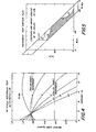
- FIGURE 1 is a plot of the number of hours to the appearance of red rust of ferrous sheet coated with various combinations of elements within the quaternary Al-Zn-Si-Mg system, illustrating the effects of Mg and Si with a fixed Al/Zn ratio of 1.26, in a salt spray environment.
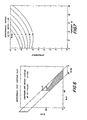
- FIGURE 2 is a contour plot showing the salt spray resistance for steel products coated with alloys within the Al-Zn-Si-Mg system at 4% Si.
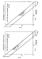
- FIGURE 3 is contour plot similar to FIGURE 2 except that the coatings contain 8% Si.
- FIGURE 4 is a plot of weight loss in an S02 containing environment of ferrous sheet coated by various combinations of elements within the quaternary Al-Zn-Si-Mg system, showing the effects of variations of Mg and Si with a fixed Al/Zn ratio of 1.26.
- FIGURE 5 is a contour plot showing weight loss in an S02-containing atmosphere for steel products coated with alloys within the Al-Zn-Si-Mg system at 4% Si.
- FIGURE 6 is a contour plot similar to FIGURE 5 except that the coatings contain 8% Si.
- FIGURE 7 is a plot of coating appearance of ferrous sheet coated by various combinations of elements within the quaternary Al-Zn-Si-Mg system, showing the effects of variations of Mg and Si with a fixed Al/Zn ratio of 1.26.
- FIGURE 8 is a contour plot showing the coating appearance for steel products coated with alloys within the Al- Zn-Si-Mg-system at 4% Si.
- FIGURE 9 is a contour plot similar to FIGURE 8 except that the coatings contain 8% Si.
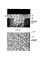
- FIGURE 10 is a photomicrograph of an etched cross-section, magnified to 500X, of an as-cast coating microstructure for a coating alloy system produced according to the prior art.
- FIGURE 11 is a photomicrograph of an etched cross-section, magnified to 500X, of the as-cast coated product according to this invention.
- FIGURE 12 is a photomicrograph of the etched surface, magnified to 200X,.of an as-cast coating microstructure for a coating alloy system produced according to the prior art..
- FIGURE 13 is a photomicrograph of the etched surface, magnified to 200X, of the as-cast, coated product according to this invention.
- The products of this invention comprise a ferrous base or substrate, such as a plain-carbon steel sheet or strip, having a ductile, adherent, corrosion resistant alloy coating metallurgically bonded to the base.
- More specifically, the ferrous base is coated with an alloy from the quaternary Al-Zn-Mg-Si system.
- Like the coatings of U.S. 3,343,930 and 3,393,089, the coatings of this invention contain cored aluminum-rich dendrites and zinc-rich interdendritic regions. Unlike the former, the coatings of this invention also contain phases discrete from the aluminum-rich dendrites and the zinc-rich interdendritic regions, which phases consist essentially of intermetallic phases of zinc, aluminum, magnesium and silicon. It is believed that the improved corrosion resistance imparted by the coating of this invention is due in part to the presence of these intermetallic phases which provide obstacles or barriers for the corrosion which occurs in the zinc-rich interdendritic regions. These obstacles created by these phases increase the time required for corrosion to reach the ferrous substrate and thereby improves the corrosion resistance of the coating.
- In broad and preferred embodiments, from a corrosion resistance point of view, the alloy overlay consists essentially of, by weight:

- While other elements may be present in the alloy in trace amounts, it is important to avoid the noble or heavy metals, particularly Pb and Cu. However, Fe may be present in an amount up to 1%.
- The starting substrate can be any ferrous material whose surface is susceptible to corrosion, e.g., iron and low carbon steels. It can have any desired shape, e.g., sheets, rods, conduits, wires and articles of convoluted and complex shapes. As is well known in the art, the surface of the starting substrate should be substantially free of organic and inorganic impurities, e.g., oil, grease and metal oxides, to ensure uniform adherence of molten alloy thereto.
- Products of this invention in the form of test panels can be prepared by a laboratory dipping technique, in which panels cut from a low carbon steel strip, whose surfaces have been suitably cleaned, e.g., freed of grease and oxides, and protected against oxidation, are dipped in a molten bath of the selected alloy having a composition which falls within the broad or preferred range of the alloy coating, withdrawn and drained. Such a technique is described hereinafter.
- The products of this invention can be prepared on a commercial.scale employing a conventional continuous hot-dip coating line, as known in the art. Two known types of continuous hot-dip coating lines are the Sendzimir line and the Selas-type direct fired furnace line. Each type of line involves gas cleaning of the ferrous base, typically a plain carbon steel strip, to prepare the strip surface for the reception of the molten alloy coating metal. In the Selas practice, for example, the steel strip is heated in a direct fired furnace to a temperature of about 1275°F (690°C) followed by treatment in a second furnace, the atmosphere of which is maintained under reducing conditions. In such second furnace the surfaces of the steel strip are protected against oxidation in a protective atmosphere of hydrogen-nitrogen, which by way of example may be 18% H2, by volume, balance nitrogen. After the steel strip leaves the second furnace, without being exposed to the atmosphere, the strip is immersed in a molten alloy bath having the composition of the coating overlay, i.e. a bath composed of the elements as defined above within the quaternary Al-Zn-Mg-Si system.The temperature of the strip as it enters the bath is below the temperature of the bath, which in the case of the coating baths according to this invention are between about 1000° to 13000F (539° to 7050C). The actual temperature of the molten alloy bath for a commercial hot-dip coating line is maintained at about 50°F (28°C) above the melting point for the alloy composition of the bath. Upon emerging from the bath, the alloy coating on the strip is passed between coating wiping dies to control the thickness of the coating, after which the coating solidifies in air or by accelerated cooling means. The resulting product is a corrosion resistant alloy coating metallurgically bonded to said steel strip.
- A laboratory method to simulate the actual time and processing parameters for such a commercial continuous hot-dip coating line has been devised. Such method, by way of example for a coating bath having a nominal composition, by weight percent, of 45Al-35Zn-10Si-10Mg, and a melting point of 1075°F (580°C), includes the following steps:
- (a) providing a cold-rolled, plain carbon (DQSK strand cast) steel sheet, the dimensions of wich are 0.635 mm x 114.3 mm x 254 mm;
- (b) cleaning the surface of said sheet with an aqueous solution;
- (c) preheating the cleaned sheet to a temperature of about 1200°F (649°C) in a reducing atmosphere of 30% H 2-N 2 ;
- (d) maintaining said sheet in said reducing atmosphere while lowering the temperature of the steel sheet to about 950°F (510°C) i.e. below the temperature of the molten coating bath;
- (e) immersing said sheet in said molten coating bath, maintained at a temperature of about 155°F (86°C) above the melting point (1075°F or 580°C);
- (f) withdrawing said sheet, after an elapsed time of about 4 seconds, and cooling the molten coating adhering to the sheets at a rate of about 40°F (22°C)/sec. during the entire solidification of the coating by directing blowers against the coated sheet.
- This laboratory method results in a coating thickness of approximately 35 µm. Due to improved coating flow characteristics for a commercially hot-dip coated product, resulting in part from the use of coating wiping dies directed against the molten coating adhering to the steel base product following withdrawal of the coated product from the molten coating bath, a typical commercial coating thickness will be between 20 and 25/um. Additionally, the bath temperature may be reduced from about 1230°F (6660C) to a range between 1135°F (6130C) to 1150°F (621°C).
- To develop a better understanding of coating alloys from within the quaternary Al-Zn-Si-Mg system, and to determine the interrelationship of the several elements when applied as a coating to a ferrous base, an intensive investigation was conducted on coated products having a coating composed of elements from the above alloy system.
- Two goals of this investigation were to identify the range of coating compositions, within such alloy system, that would (1) provide a high level of corrosion resistance to an underlying steel base, and (2) be acceptable as a coating from an appearance standpoint. The criterion for corrosion resistance performance was to identify those alloy coatings, which when applied to a ferrous substrate, would perform as well or better, preferably twice as well, as 55Al-Zn.
- With respect to appearance, a visual evaluation, the appearance criteria include such features as color, texture and reflectivity. A low rating, on a scale of 0 to 10, for example, would be given to a coating which was discolored and/or rough due to the presence of scum. A high rating was given to a coating which was smooth and shiny, and was characterized by a satin sheen finish.having a fine spangle.
- With such goals defined, a number of samples were prepared using coating alloys from within the above quarternary alloy system. A statistical analysis of -the corrosion and appearance data was employed to identify the most promising coating compositions in the quaternary Al-Zn-Mg-Si system. The data generated by this investigation enabled the inventors to calculate the effect of certain of the four elements on the performance of coating compositions within such alloy system.
- One important discovery from this investigation, which discovery is confirmed by the several FIGURES hereinafter described in detail, was that within the alloy ranges for the coatings on products of this invention there is a preferred Al/Zn ratio between 1.2 and 1.3. While such ratio is preferred, good results are achievable within the broader range of 1.0 to 1.5 for the Al/Zn.
- Turning now to the accompanying FIGURES, particularly FIGURES 1-9, the plots thereof depicting performance values were produced by regression analysis from the data of a large number of test samples. FIGURES 1-6 represent the calculated hours per 25/um of coating to the designated degree of rusting or weight loss, at the selected silicon level, for different aluminum, zinc, and magnesium concentrations.
- However, while only several contour lines have been illustrated for purposes of simplifying the drawings, it should be understood that many such lines could have been included. To illustrate this feature without unduly complicating the drawings, an arrow is shown within an area to indicate that further improvements will be observed in the coating with compositional changes in the direction of the arrow.
- FIGURE 1 shows the salt spray resistance of various alloy coated products as a function of silicon and magnesium, for coatings at Al/Zn ='1.26. There is a nonlinear effect of silicon on salt spray resistance with a minimum performance at between about 3% to 3.5%. Though magnesium additions improve the salt spray resistance, the best results occur when %Si>3.5%. By inspection of FIGURE 1, it will be seen that the condition for improving salt spray resistance by a factor of two over 55 Al-Zn sheet is:

- FIGURES 2 and 3 are contour plots showing the salt spray resistance for coatings within the Al-Zn-Mg-Si system for 4% and 8% silicon, respectively. Optimum performance is shown by the shaded areas.
- FIGURE 4 shows the S02 resistance of coatings with Al/Zn = 1.26. Again, nonlinear effect of silicon appear and the positive interaction between silicon and magnesium is readily seen. For two times the resistance to SO2, or one-half the weight loss, than 55Al-Zn sheet, it is important to satisfy the following general conditions:

- FIGURES 5 and 6 are contour plots for the weight loss in SO? environments of coating compositions within the Al-Zn-Si-Mg system. Since the contours represent weight loss after 50 cycles, the lower the value the better the coating performance. As in the case of the salt-spray projections (FIGURES 2 and 3) aluminum, zinc, and magnesium contents were varied at two silicon levels of 4% and 8%, FIGURES 5 and 6 respectively. Optimum performance is shown by the shaded areas.
- FIGURE 7 shows the appearance of as-cast coatings with Al/Zn = 1.26. It was observed that silicon counters the adverse effects on appearance caused by magnesium additions,hence, for a coating with equivalent or better appearance than coatings of 55Al-Zn sheets the following condition should be satisfied:

- Contour plots of appearance ratings of Al-Zn-Mg-Si, at 4% and 8% silicon, are shown in FIGURES 8 and 9. The higher numbers represent the coatings with the preferred appearance. For purposes of clarification, "9" represents a very good coating from an appearance standpoint. On this same scale, a "10" would be equivalent to the best appearing commercial hot-dipped coatings. The optimum appearance for the coatings are shown by the shaded areas.
- If, for example, FIGURES 2, 5 and 8 or FIGURES 3, 6 and 9, were superimposed on each other, to select a composition which optimized the coating's performance in all three tests, namely, (1) salt spray test, (2) Kesternich test, and (3) appearance, it would be found that the optimum ratio of Al/Zn is between 1.2 and 1.3, and magnesium and silicon are each present in an amount of about 10%. However, for a commercial product it should be noted that situations may arise where it may be desirable to enhance the coating performance in one test while settling for less than optimum performance in another.
- There are further considerations which are not apparent from the above FIGURES, but must be considered for a commercial hot-dip coating operation. Such considerations involve the properties of the coating bath. For example, at 20% Mg combustion in air will occur. Thus, in order to avoid the costly expenditure of a means to protect the coating bath, e.g. enclosing the bath in a nitrogen atmosphere, magnesium in the molten alloy bath should not exceed 20%. Further, when magnesium is present in an amount of 6% or more, for optimum bath fluidity it is desirable to have silicon present in the bath at a level of at least 5%, preferably at least 7%.
- Based on the information gathered from FIGURES.1 to 9, the broad and preferred compositional ranges for the alloy coating constituents set forth hereinbefore were established. The numerical values for compositional ranges or specific constituents, as used herein, are by weight percent.
- Coated panels according to the prior art having the optimum corrosion resistance values currently available in a commercial hot-dip metallic coated product, and panels of this invention were prepared in the laboratory by dipping low-carbon steel panels, three panels each, in various molten metal baths having the compositions, by weight percent, listed in TABLE I.

- The panels were removed from the molten metal bath and the excess coating metal adhering thereto drained leaving an adherent, corrosion resistant coating metallurgically bonded to the steel base. Metallurgical bond, as known in the art (Metallurgical Principles for Engineers by J.G.Tweeddale, p. 273, published by London ILIFFE Books Ltd. 1962) and used herein, refers to the type of joint in which two dissimilar metals are brought into contact and so treated that an intermediate alloy is formed between them which gives a direct metallurgical link between the two dissimilar metals.
- To determine the corrosion resistance performance of such coated panels, the panels were subjected to two accelerated laboratory tests, namely, (1) salt spray test, (unprotected edges), designated as ASTM Standard B117-73, and (2) Kesternich test, (unprotected edges), designated as DIN 50018. The test results for the alloy coated panels are listed in TABLES II and'III. There were differences in coating thicknesses which affected the corrosion resistance performace of the coated test panels, i.e.,
test panels 1 and 3 had thicker coatings thantest panels panels 1 and 3 cannot be directly compared to those forpanels test panels 1 and 3 andtest panels 
- The test data of TABLES II and III illustrate the superior performance of the coated panels (3, 4) according to this invention over comparably produced coated panels (1, 2) according to the prior art, i.e. U.S. Patent No. 3,343,930, believed to have the best overall corrosion resistance in a commercial hot-dip metallic coated product. The superiority is on the order of two to three times better.
- Having established the superior corrosion resistance performance (TABLE III) of alloy coated products, whose coating falls within the broad and preferred ranges described above, an examination of the coating microstructure and corrosion mechanism may be helpful to explain such superiority.
- For this examination, as-cast alloy coated panels, having nominal coating compositions comparable to
alloy coatings 1 and 4 in TABLE I, were prepared for analysis under the microscope. All coated panels that were tested during the investigation were processed by a rapid-cooling practice described in U.S. Patent No. 3,782,909. That is, all alloy coatings were forced air-cooled at a rate of at least 20°F (11°C)/sec., more specifically at a rate of about 40°F (220C)/sec., during the entire solidification of the coating. It is believed that this brief comment on the processing of the alloy coated panels may be helpful in understanding the microstructure and corrosion mechanism of 55Al-Zn sheet, as well as the microstructure and corrosion mechanism of the alloy coatings of this invention. - FIGURE 10 .is an etched cross-section, magnified to 500X, of the coated panel, having a coating composition comparable to #1 of TABLE I. Under the rapid-cooling processing conditions of U.S. Patent No. 3,782,909, the coating on 55Al-Zn sheet develops a nonequilibrium and complex structure. The first solid formed during the coating solidification is alpha-
aluminum 12 at about 80% Al leading to a cored dendritic structure in which the final liquid to solidify is substantially lower in aluminum content (zinc-rich) 10 and whose microstructure is quite fine and not well defined. A further feature of the 55Al-Zn sheet coating is a thin intermetallic layer 14 between thesteel base 16 andcoating overlay 18. Thus, the coating microstructure of 55Al-Zn sheet may be described as comprising cored aluminum-rich dendrites 10 and zinc-richinterdendritic constituents 12 overlying a thin intermetallic layer 14. - The mode of corrosion of 55Al-Zn may be described as one of preferential corrosion, that is, the zinc-rich
interdendritic portion 12 of the coating corrodes preferentially. Further, the intermetallic layer 14 is believed to be cathodic to the steel substrate as well as to the other components of the coating. Accordingly, this layer 14 appears to function as an electrochemical barrier that prevents corrosion of the steel substrate subsequent to interdendritic corrosion of theoverlay 18. Thus, the excellent corrosion resistance performance of 55Al-Zn.sheet, particularly over the conventional coatings, such as aluminized or galvanized sheet, may be attributed to the interrelationship of (1) the coating overlay comprising the cored aluminum-rich dendrites and zinc-rich interdendritic constituents, and (2). the intermetallic layer. - Despite the excellent performance of 55Al-Zn sheet, the present invention describes a method for producing an alloy coating for steel which is capable of surpassing the performance of 55Al-Zn sheet coatings by as much as two-fold.
- FIGURE 11 is a photomicrograph, similar to FIGURE 10, showing an as-cast coated product having a coating comparable to #4 of TABLE I, and produced according to this invention. The coating overlay microstructure illustrated in FIGURE 11 is similar, yet more complex than the microstructure of 55Al-Zn sheet overlay illustrated in FIGURE 10. For example, the
coating overlay 20 consists of a mixture of cored aluminum-rich dendrites 22 containing zinc-richinterdendritic constituents 24, andintermetallic compounds 26 of zinc, aluminum, magnesium and silicon. While a number of intermetallic compounds have been identified, two of the prominent compounds are MgZn2 and Mg2Si. Additionally, SiO2 has been identified in the coating as crystals embedded in Mg2Si. Further, where Mg is present in the coating in an amount of at least about 10%, as found in #3, the phase identified as Mg32(Al,Zn)49 will be found. - The improved performance of alloy coatings within the scope of this invention has been attributed to several possible factors. FIGURES 12 and 13 are photomicrographs, magnified to 200 X, of a selected area on the etched surface of 55Al-Zn sheet and the coating of this invention, respectively, showing an aluminum-rich dendrite.
- The dendrites featured in such FIGURES are characterized by a
core 10A, 22A (FIGURES 12 and 13, respectively) and a plurality of branches orarms 10B, 22B emanating therefrom as angles normal to said core. At high magnification these branches or arms are readily observable and the perpendicular distances between such branches or arms can be measured. These measured distances are called the dendrite arm spacings (DAS). For a more detailed discussion of dendrite formation, as well as dendrite arm spacing, reference is made to Solidification Processing by Merton C. Flemings, pp. 146-148, published by McGraw-Hill Inc. 1974. In any case, for comparably produced coatings, the'DAS for the coatings of this invention are at least 3 µm smaller than the DAS for 55Al-Zn sheet. For reference, the DAS for the coatings of this invention produced by the rapid cooling technique described above, will fall within the range of less than 10 m, preferably between about 3 to 9/um.In contrast to this, a commercially produced 55Al- Zn sheet will have a DAS in the range of 10 to 13 µm. - It is the opinion of the inventors that the atmospheric corrosion mechanism for the alloy coatings of this invention is similar to that established for 55Al-Zn sheet coatings. That is, such mechanism is that of preferential corrosion of one phase or microstructural constituent. The first factor resulting in the improved performance of the coated products of this invention is the smaller DAS found in the overlay structure over that of the overlay structure of a comparably produced 55Al-Zn sheet. With the smaller DAS the preferential corrosion of the interdendritic phase or constituent must follow a more circuitous route to reach the intermetallic layer. Secondly, if this route of preferential corrosion can be delayed by added barriers, the rate of corrosion must necessarily decrease and the coating performance increase. While the particular mode of corrosion has not been determined for the coatings of this invention, it is theorized that silicon and magnesium, when combined with aluminum and zinc, act in some unexpected manner to improve the corrosion resistance of the coatings of this invention. Without desiring to be bound to a given theory, it is believed that the following represents an approach by which the combination of silicon and magnesium act to improve such corrosion resistance.
- Silicon added in small quantities, up to about 3% by weight, to Al-Zn hot-dip coatings appears in patches at the interface of the intermetallic alloy layer and the coating overlay. Silicon also occurs in the form of particles in the overlay, which particles act as cathodes in an Al-Zn matrix and thus increase the corrosion rate. The inventors believe this apparent cathodic activity accounts for the detrimental effect of small silicon additions. As silicon concentration is increased to above about 3% by weight of-the Al-Zn coating, the patches at the intermetallic alloy layer-coating overlay interface link-up and form a continuous silicon-rich barrier layer. It is theorized that in Al-Zn coatings this silicon barrier would increase the corrosion resistance by adding an extra corrosion-resistant layer between the environment and the steel substrate, thus accounting for the beneficial_effects of higher silicon concentrations. Further, the inventors believe that magnesium additions enhance these beneficial effects by combining with silicon in the coating overlay to form Mg2Si, which is not cathodic to the Al-Zn matrix. Thus, in magnesium-free Al-Zn alloy coatings most of the silicon in the coating overlay is free silicon which may be detrimental to the corrosion performance of the product. However, in the alloy coatings of this invention, most silicon in the coating overlay is combined as Mg2Si (and to a lesser extent as SiO2), which contributes to the corrosion resistance of the coated product.
Claims (10)
characterized in that said overlay is an alloy from essentially within the quaternary Al-Zn-Si-Mg system having a metallurgical structure containing (1) cored aluminum-rich dendrites having dendrite arm spacings (DAS) of less than 10/um, (2) zinc-rich interdentritic regions, and (3) intermetallic phases of zinc, aluminum, magnesium and silicon; said alloy consisting essentially of, by weight, 3 - 20% magnesium and 3 - 15% silicon, balance aluminum and zinc, where the

characterized in that said DAS are in the range of 3 to 9/um, and said intermetallic phases are selected from the group consisting of Mg2Si, MgZn2, Si02, and Mg 32 (Al,Zn)49.


characterized in that said cooling is conducted during substantially the entire solidification range of said coating, at a rate of at least 20° F(11°C)/second.
Applications Claiming Priority (2)
| Application Number | Priority Date | Filing Date | Title |
|---|---|---|---|
| US06/391,217 US4401727A (en) | 1982-06-23 | 1982-06-23 | Ferrous product having an alloy coating thereon of Al-Zn-Mg-Si Alloy, and method |
| US391217 | 1982-06-23 |
Publications (3)
| Publication Number | Publication Date |
|---|---|
| EP0106021A2 true EP0106021A2 (en) | 1984-04-25 |
| EP0106021A3 EP0106021A3 (en) | 1984-09-12 |
| EP0106021B1 EP0106021B1 (en) | 1986-08-27 |
Family
ID=23545759
Family Applications (1)
| Application Number | Title | Priority Date | Filing Date |
|---|---|---|---|
| EP83106105A Expired EP0106021B1 (en) | 1982-06-23 | 1983-06-22 | Ferrous product having an alloy coating thereon of aluminium-zinc-magnesium-silicon, and method |
Country Status (14)
| Country | Link |
|---|---|
| US (1) | US4401727A (en) |
| EP (1) | EP0106021B1 (en) |
| JP (1) | JPS5956570A (en) |
| KR (1) | KR880000458B1 (en) |
| AU (1) | AU553549B2 (en) |
| BR (1) | BR8303298A (en) |
| CA (1) | CA1204970A (en) |
| DE (1) | DE3365647D1 (en) |
| ES (1) | ES523486A0 (en) |
| FI (1) | FI73007C (en) |
| IN (1) | IN160994B (en) |
| NO (1) | NO162622C (en) |
| NZ (1) | NZ204672A (en) |
| ZA (1) | ZA833901B (en) |
Cited By (2)
| Publication number | Priority date | Publication date | Assignee | Title |
|---|---|---|---|---|
| JP2001115247A (en) * | 1999-08-09 | 2001-04-24 | Nippon Steel Corp | Zn-Al-Mg-Si alloy-plated steel excellent in corrosion resistance and method for producing the same |
| EP2250296B1 (en) | 2008-03-13 | 2020-10-14 | Bluescope Steel Limited | Metal-coated steel strip and method of manufacturing thereof |
Families Citing this family (51)
| Publication number | Priority date | Publication date | Assignee | Title |
|---|---|---|---|---|
| US4650694A (en) * | 1985-05-01 | 1987-03-17 | Burlington Industries, Inc. | Method and apparatus for securing uniformity and solidity in liquid jet electrostatic applicators using random droplet formation processes |
| US5135817A (en) * | 1988-07-06 | 1992-08-04 | Kabushiki Kaisha Kobe Seiko Sho | Zn-Mg alloy vapor deposition plated metals of high corrosion resistance, as well as method of producing them |
| US5002837A (en) * | 1988-07-06 | 1991-03-26 | Kabushiki Kaisha Kobe Seiko Sho | Zn-Mg alloy vapor deposition plated metals of high corrosion resistance, as well as method of producing them |
| EP0457315A1 (en) * | 1990-05-17 | 1991-11-21 | Max Frank GmbH & Co. KG | Reinforcement connector and concrete-construction with such a connector |
| JP2777571B2 (en) * | 1991-11-29 | 1998-07-16 | 大同鋼板株式会社 | Aluminum-zinc-silicon alloy plating coating and method for producing the same |
| JPH11343552A (en) * | 1998-05-28 | 1999-12-14 | Nkk Corp | Hot-dip Al-Zn alloy plated steel sheet with excellent corrosion resistance |
| JP2000064011A (en) * | 1998-08-13 | 2000-02-29 | Nippon Steel Corp | Hot-dip Zn-Mg-Al coated steel sheet with excellent resistance to cracking |
| JP4199404B2 (en) * | 1999-03-15 | 2008-12-17 | 新日本製鐵株式会社 | High corrosion resistance plated steel sheet |
| CN1238551C (en) * | 1999-03-19 | 2006-01-25 | 新日本制铁株式会社 | Tin-plated or aluminum-plated surface-treated steel with good corrosion resistance |
| JP4469030B2 (en) * | 1999-04-05 | 2010-05-26 | 新日本製鐵株式会社 | Aluminum plated steel plate for automobile fuel tank with excellent corrosion resistance |
| US6465114B1 (en) * | 1999-05-24 | 2002-10-15 | Nippon Steel Corporation | -Zn coated steel material, ZN coated steel sheet and painted steel sheet excellent in corrosion resistance, and method of producing the same |
| JP4267184B2 (en) * | 1999-06-29 | 2009-05-27 | 新日本製鐵株式会社 | Hot-dip aluminized steel sheet with excellent corrosion resistance and appearance and manufacturing method thereof |
| US6689489B2 (en) | 1999-10-07 | 2004-02-10 | Isg Technologies, Inc. | Composition for controlling spangle size, a coated steel product, and a coating method |
| EP1218563B1 (en) | 1999-10-07 | 2011-04-06 | Severstal Sparrows Point, LLC. | A coated steel product and a steel product coating method |
| JP4153631B2 (en) * | 1999-10-21 | 2008-09-24 | 新日本製鐵株式会社 | Molten Al-Mg-Si alloy-plated steel wire with excellent corrosion resistance and method for producing the same |
| JP4537599B2 (en) * | 2000-03-10 | 2010-09-01 | 新日本製鐵株式会社 | High corrosion resistance Al-based plated steel sheet with excellent appearance |
| JP3684135B2 (en) * | 2000-04-11 | 2005-08-17 | 新日本製鐵株式会社 | Si-containing high-strength hot-dip galvanized steel sheet with excellent corrosion resistance and method for producing the same |
| JP2002060978A (en) * | 2000-08-17 | 2002-02-28 | Nippon Steel Corp | Steel with metal coating and excellent corrosion resistance |
| JP2003136629A (en) * | 2001-11-01 | 2003-05-14 | Daido Metal Co Ltd | Multilayered material and method for manufacturing multilayered material |
| JP4171232B2 (en) * | 2002-03-08 | 2008-10-22 | 新日本製鐵株式会社 | Hot-dip galvanized steel with excellent surface smoothness |
| JP2004107730A (en) * | 2002-09-19 | 2004-04-08 | Jfe Steel Kk | Hot-dip Al-Zn coated steel sheet with excellent bending workability and peeling resistance |
| JP3843057B2 (en) * | 2002-10-23 | 2006-11-08 | 新日本製鐵株式会社 | Hot-dip galvanized steel sheet with excellent appearance quality and manufacturing method of galvanized steel sheet |
| US7241350B2 (en) * | 2002-12-03 | 2007-07-10 | Greenkote (Israel) Ltd. | Corrosion resistant poly-metal diffusion coatings and a method of applying same |
| JP5020228B2 (en) * | 2005-04-05 | 2012-09-05 | ブルースコープ・スティール・リミテッド | Metal coated steel strip |
| WO2007108496A1 (en) * | 2006-03-20 | 2007-09-27 | Nippon Steel Corporation | Highly corrosion-resistant hot dip galvanized steel stock |
| WO2007118939A1 (en) | 2006-04-19 | 2007-10-25 | Arcelor France | Method of producing a welded part having very high mechanical properties from a rolled and coated sheet |
| ES2636442T3 (en) * | 2006-05-15 | 2017-10-05 | Thyssenkrupp Steel Europe Ag | Flat steel product provided with an anticorrosive coating and manufacturing process |
| ES2629109T3 (en) * | 2006-05-15 | 2017-08-07 | Thyssenkrupp Steel Europe Ag | Procedure for the manufacture of a flat steel product coated with a corrosion protection system |
| JP5119465B2 (en) * | 2006-07-19 | 2013-01-16 | 新日鐵住金株式会社 | Alloy having high amorphous forming ability and alloy plating metal material using the same |
| US20080041499A1 (en) * | 2006-08-16 | 2008-02-21 | Alotech Ltd. Llc | Solidification microstructure of aggregate molded shaped castings |
| AU2008253615B2 (en) * | 2007-05-24 | 2013-05-02 | Bluescope Steel Limited | Metal-coated steel strip |
| JP5815947B2 (en) * | 2008-02-07 | 2015-11-17 | ブルースコープ・スティール・リミテッドBluescope Steel Limited | How to produce a coating on a steel strip |
| EP3757245A1 (en) | 2009-03-13 | 2020-12-30 | Bluescope Steel Limited | Corrosion protection with al / zn-based coatings |
| AU2017203262A1 (en) * | 2009-03-13 | 2017-06-08 | Bluescope Steel Limited | Corrosion protection with al/zn-based coatings |
| MY179278A (en) * | 2009-05-28 | 2020-11-03 | Bluescope Steel Ltd | Metal-coated steel strip |
| RU2532769C2 (en) | 2010-06-09 | 2014-11-10 | Сано Когио Кабусики Кайся | Metal tube for vehicle pipes and method of its surface processing |
| CN102011082A (en) * | 2010-11-12 | 2011-04-13 | 上海大学 | Hot immersion plating process method for Al-Zn-Si-Mg alloy plating layer |
| JP5751093B2 (en) * | 2011-08-24 | 2015-07-22 | 新日鐵住金株式会社 | Surface-treated hot-dip galvanized steel |
| MX350136B (en) | 2012-05-25 | 2017-08-28 | Shiloh Ind Inc | Sheet metal piece having weld notch and method of forming the same. |
| MX353799B (en) | 2012-06-29 | 2018-01-30 | Shiloh Ind Inc | Welded blank assembly and method. |
| KR20210014759A (en) | 2012-08-01 | 2021-02-09 | 블루스코프 스틸 리미티드 | Metal coated steel strip |
| AU2013332257A1 (en) | 2012-10-17 | 2015-04-09 | Bluescope Steel Limited | Method of producing metal-coated steel strip |
| ES2807509T3 (en) * | 2012-10-18 | 2021-02-23 | Bluescope Steel Ltd | Metal Coated Steel Strip Production Procedure |
| MX381438B (en) | 2012-11-30 | 2025-03-04 | Twb Company Llc | METHOD FOR FORMING A WELD NOTCH IN A PIECE OF SHEET METAL. |
| US9956636B2 (en) | 2013-03-14 | 2018-05-01 | Shiloh Industries, Inc. | Welded blank assembly and method |
| CN104253577A (en) * | 2013-06-26 | 2014-12-31 | 北京实力源科技开发有限责任公司 | Weather-resistant metal support structure |
| JP6368730B2 (en) * | 2015-03-02 | 2018-08-01 | Jfe鋼板株式会社 | Molten Al-Zn-Mg-Si plated steel sheet and method for producing the same |
| JP6528627B2 (en) * | 2015-09-29 | 2019-06-12 | 日本製鉄株式会社 | Plating steel |
| CN111051558B (en) | 2017-09-08 | 2022-05-31 | 日本制铁株式会社 | Zn-Al-Mg-based plated steel sheet |
| KR102463468B1 (en) | 2017-12-12 | 2022-11-04 | 현대자동차주식회사 | Aluminium alloy for die casting |
| KR102109242B1 (en) * | 2017-12-26 | 2020-05-11 | 주식회사 포스코 | Multi-layered zinc alloy plated steel material having excellent spot weldability and corrosion resistance |
Family Cites Families (7)
| Publication number | Priority date | Publication date | Assignee | Title |
|---|---|---|---|---|
| US3782909A (en) * | 1972-02-11 | 1974-01-01 | Bethlehem Steel Corp | Corrosion resistant aluminum-zinc coating and method of making |
| US4029478A (en) * | 1976-01-05 | 1977-06-14 | Inland Steel Company | Zn-Al hot-dip coated ferrous sheet |
| US4350539A (en) * | 1979-11-08 | 1982-09-21 | Bethlehem Steel Corporation | Method of improving the ductility of the coating of an aluminum-zinc alloy coated ferrous product |
| US4287009A (en) * | 1979-11-08 | 1981-09-01 | Bethlehem Steel Corporation | Method of producing an aluminum-zinc alloy coated ferrous product to improve corrosion resistance |
| DE3169319D1 (en) * | 1980-03-25 | 1985-04-25 | Centre Rech Metallurgique | Hot dip coating process |
| JPS56156745A (en) * | 1980-05-06 | 1981-12-03 | Shimada Phys & Chem Ind Co Ltd | Treatment of iron surface |
| LU82598A1 (en) * | 1980-07-09 | 1982-02-17 | Arbed | PROCESS AND PLANT FOR HOT METALLIZATION OF METAL OBJECTS |
-
1982
- 1982-06-23 US US06/391,217 patent/US4401727A/en not_active Expired - Fee Related
-
1983
- 1983-05-27 CA CA000429104A patent/CA1204970A/en not_active Expired
- 1983-05-30 ZA ZA833901A patent/ZA833901B/en unknown
- 1983-06-14 IN IN746/CAL/83A patent/IN160994B/en unknown
- 1983-06-21 FI FI832268A patent/FI73007C/en not_active IP Right Cessation
- 1983-06-21 KR KR1019830002790A patent/KR880000458B1/en not_active Expired
- 1983-06-21 BR BR8303298A patent/BR8303298A/en not_active IP Right Cessation
- 1983-06-22 ES ES523486A patent/ES523486A0/en active Granted
- 1983-06-22 EP EP83106105A patent/EP0106021B1/en not_active Expired
- 1983-06-22 DE DE8383106105T patent/DE3365647D1/en not_active Expired
- 1983-06-22 NO NO832270A patent/NO162622C/en unknown
- 1983-06-22 NZ NZ204672A patent/NZ204672A/en unknown
- 1983-06-22 AU AU16162/83A patent/AU553549B2/en not_active Ceased
- 1983-06-23 JP JP58113619A patent/JPS5956570A/en active Granted
Cited By (4)
| Publication number | Priority date | Publication date | Assignee | Title |
|---|---|---|---|---|
| JP2001115247A (en) * | 1999-08-09 | 2001-04-24 | Nippon Steel Corp | Zn-Al-Mg-Si alloy-plated steel excellent in corrosion resistance and method for producing the same |
| EP2108712A3 (en) * | 1999-08-09 | 2010-12-29 | Nippon Steel Corporation | Highly corrosion resistant Zn-Al-Mg-Si alloy-plated steel material and process for its production |
| EP2250296B1 (en) | 2008-03-13 | 2020-10-14 | Bluescope Steel Limited | Metal-coated steel strip and method of manufacturing thereof |
| EP2250297B1 (en) | 2008-03-13 | 2021-01-13 | Bluescope Steel Limited | Metal-coated steel strip and method of manufacturing thereof |
Also Published As
| Publication number | Publication date |
|---|---|
| AU1616283A (en) | 1984-01-05 |
| EP0106021A3 (en) | 1984-09-12 |
| FI832268A0 (en) | 1983-06-21 |
| DE3365647D1 (en) | 1986-10-02 |
| JPS5956570A (en) | 1984-04-02 |
| NO162622C (en) | 1990-01-24 |
| AU553549B2 (en) | 1986-07-17 |
| EP0106021B1 (en) | 1986-08-27 |
| NZ204672A (en) | 1986-01-24 |
| IN160994B (en) | 1987-09-05 |
| KR840005175A (en) | 1984-11-05 |
| US4401727A (en) | 1983-08-30 |
| ES8501449A1 (en) | 1984-11-16 |
| FI73007B (en) | 1987-04-30 |
| JPH0321627B2 (en) | 1991-03-25 |
| ZA833901B (en) | 1984-02-29 |
| ES523486A0 (en) | 1984-11-16 |
| KR880000458B1 (en) | 1988-04-06 |
| FI73007C (en) | 1987-08-10 |
| CA1204970A (en) | 1986-05-27 |
| FI832268L (en) | 1983-12-24 |
| BR8303298A (en) | 1984-02-07 |
| NO162622B (en) | 1989-10-16 |
| NO832270L (en) | 1983-12-27 |
Similar Documents
| Publication | Publication Date | Title |
|---|---|---|
| EP0106021B1 (en) | Ferrous product having an alloy coating thereon of aluminium-zinc-magnesium-silicon, and method | |
| AU544400B2 (en) | Zinc-aluminum alloys and coatings | |
| US4029478A (en) | Zn-Al hot-dip coated ferrous sheet | |
| JPS648702B2 (en) | ||
| JP3357471B2 (en) | Zn-Mg-Al-based hot-dip galvanized steel excellent in corrosion resistance and method for producing the same | |
| JP2000328216A (en) | High corrosion resistant plated steel sheet | |
| JP2783452B2 (en) | Manufacturing method of galvannealed steel sheet | |
| US5091150A (en) | Zinc-aluminium based alloy for coating steel products | |
| JPH0518903B2 (en) | ||
| Lynch | Hot-dip galvanizing alloys | |
| EP0048270B1 (en) | Zinc-aluminum coatings | |
| JPS648704B2 (en) | ||
| JP3126623B2 (en) | Rustproof steel plate for fuel tank | |
| JPS648069B2 (en) | ||
| JP2002173753A (en) | HOT DIP Zn-Al ALLOY PLATED STEEL SHEET HAVING EXCELLENT BLACKENING RESISTANCE AND ITS PRODUCTION METHOD | |
| JP2004277839A (en) | Zinc-based metal-coated steel | |
| JP3009262B2 (en) | Hot-dip zinc aluminum alloy plating coating with excellent fatigue properties | |
| JPS63134653A (en) | Manufacture of alloy-plated steel material excellent in corrosion resistance and workability | |
| JP3045264B2 (en) | Manufacturing method of alloyed hot-dip galvanized steel sheet | |
| JP2756547B2 (en) | Hot-dip Zn-based plating of hard-to-plate steel sheet | |
| CA1065204A (en) | Zinc-aluminum eutectic alloy coating process and article | |
| JP3357466B2 (en) | Alloyed hot-dip galvanized steel and manufacturing method thereof | |
| JP2765078B2 (en) | Alloyed hot-dip coated steel sheet and method for producing the same | |
| JP2724045B2 (en) | Method for producing chromium-containing steel sheet plated with hot-dip zinc or zinc alloy | |
| JP3033355B2 (en) | High corrosion resistance plated steel sheet with excellent plating adhesion |
Legal Events
| Date | Code | Title | Description |
|---|---|---|---|
| PUAI | Public reference made under article 153(3) epc to a published international application that has entered the european phase |
Free format text: ORIGINAL CODE: 0009012 |
|
| AK | Designated contracting states |
Designated state(s): BE DE FR GB IT LU NL SE |
|
| PUAL | Search report despatched |
Free format text: ORIGINAL CODE: 0009013 |
|
| AK | Designated contracting states |
Designated state(s): BE DE FR GB IT LU NL SE |
|
| 17P | Request for examination filed |
Effective date: 19841203 |
|
| GRAA | (expected) grant |
Free format text: ORIGINAL CODE: 0009210 |
|
| AK | Designated contracting states |
Kind code of ref document: B1 Designated state(s): BE DE FR GB IT LU NL SE |
|
| REF | Corresponds to: |
Ref document number: 3365647 Country of ref document: DE Date of ref document: 19861002 |
|
| ITF | It: translation for a ep patent filed | ||
| ET | Fr: translation filed | ||
| PLBE | No opposition filed within time limit |
Free format text: ORIGINAL CODE: 0009261 |
|
| STAA | Information on the status of an ep patent application or granted ep patent |
Free format text: STATUS: NO OPPOSITION FILED WITHIN TIME LIMIT |
|
| 26N | No opposition filed | ||
| ITTA | It: last paid annual fee | ||
| PGFP | Annual fee paid to national office [announced via postgrant information from national office to epo] |
Ref country code: FR Payment date: 19930512 Year of fee payment: 11 |
|
| PGFP | Annual fee paid to national office [announced via postgrant information from national office to epo] |
Ref country code: SE Payment date: 19930517 Year of fee payment: 11 |
|
| PGFP | Annual fee paid to national office [announced via postgrant information from national office to epo] |
Ref country code: GB Payment date: 19930518 Year of fee payment: 11 |
|
| PGFP | Annual fee paid to national office [announced via postgrant information from national office to epo] |
Ref country code: DE Payment date: 19930527 Year of fee payment: 11 |
|
| PGFP | Annual fee paid to national office [announced via postgrant information from national office to epo] |
Ref country code: BE Payment date: 19930614 Year of fee payment: 11 |
|
| PGFP | Annual fee paid to national office [announced via postgrant information from national office to epo] |
Ref country code: LU Payment date: 19930618 Year of fee payment: 11 |
|
| PGFP | Annual fee paid to national office [announced via postgrant information from national office to epo] |
Ref country code: NL Payment date: 19930630 Year of fee payment: 11 |
|
| EPTA | Lu: last paid annual fee | ||
| PG25 | Lapsed in a contracting state [announced via postgrant information from national office to epo] |
Ref country code: LU Free format text: LAPSE BECAUSE OF NON-PAYMENT OF DUE FEES Effective date: 19940622 Ref country code: GB Effective date: 19940622 |
|
| PG25 | Lapsed in a contracting state [announced via postgrant information from national office to epo] |
Ref country code: SE Effective date: 19940623 |
|
| PG25 | Lapsed in a contracting state [announced via postgrant information from national office to epo] |
Ref country code: BE Effective date: 19940630 |
|
| BERE | Be: lapsed |
Owner name: BETHLEHEM STEEL CORP. Effective date: 19940630 |
|
| PG25 | Lapsed in a contracting state [announced via postgrant information from national office to epo] |
Ref country code: NL Effective date: 19950101 |
|
| EUG | Se: european patent has lapsed |
Ref document number: 83106105.6 Effective date: 19950110 |
|
| GBPC | Gb: european patent ceased through non-payment of renewal fee |
Effective date: 19940622 |
|
| NLV4 | Nl: lapsed or anulled due to non-payment of the annual fee | ||
| PG25 | Lapsed in a contracting state [announced via postgrant information from national office to epo] |
Ref country code: FR Effective date: 19950228 |
|
| PG25 | Lapsed in a contracting state [announced via postgrant information from national office to epo] |
Ref country code: DE Effective date: 19950301 |
|
| EUG | Se: european patent has lapsed |
Ref document number: 83106105.6 |
|
| REG | Reference to a national code |
Ref country code: FR Ref legal event code: ST |