EP0105938A1 - Support for tubes of a tube bundle inside a vessel - Google Patents
Support for tubes of a tube bundle inside a vessel Download PDFInfo
- Publication number
- EP0105938A1 EP0105938A1 EP82109265A EP82109265A EP0105938A1 EP 0105938 A1 EP0105938 A1 EP 0105938A1 EP 82109265 A EP82109265 A EP 82109265A EP 82109265 A EP82109265 A EP 82109265A EP 0105938 A1 EP0105938 A1 EP 0105938A1
- Authority
- EP
- European Patent Office
- Prior art keywords
- tubes
- support rods
- tube bundle
- support
- cross
- Prior art date
- Legal status (The legal status is an assumption and is not a legal conclusion. Google has not performed a legal analysis and makes no representation as to the accuracy of the status listed.)
- Withdrawn
Links
Images
Classifications
-
- F—MECHANICAL ENGINEERING; LIGHTING; HEATING; WEAPONS; BLASTING
- F28—HEAT EXCHANGE IN GENERAL
- F28F—DETAILS OF HEAT-EXCHANGE AND HEAT-TRANSFER APPARATUS, OF GENERAL APPLICATION
- F28F9/00—Casings; Header boxes; Auxiliary supports for elements; Auxiliary members within casings
- F28F9/007—Auxiliary supports for elements
- F28F9/013—Auxiliary supports for elements for tubes or tube-assemblies
- F28F9/0135—Auxiliary supports for elements for tubes or tube-assemblies formed by grids having only one tube per closed grid opening
Definitions
- the invention relates to a holder for the tubes of a tube bundle within a container, in particular for a heat exchanger consisting of jacket and tube bundle or a reactor vessel, with support rods arranged in tiers, which extend through the spaces between parallel rows of tubes and the tubes on their outer circumference radially supportive touch.
- the support rods of each tier are usually attached to a ring that surrounds the tube bundle and is attached to the inner wall of the container.
- the support rods are arranged in the interior of the container through which a medium flows, the support rods represent a flow resistance which causes a pressure drop.
- the levels of straight support bars, which cross each other in stages, have therefore been arranged at greater distances from one another (US Pat. No. 4,127,165).
- DE-OS 27 06 049 US 4 127 165
- each level of straight support rods consists of a plurality of intersecting support rods in closely spaced planes.
- the purpose of supporting tubes of a tube bundle in container construction along their length is to protect the tubes through which a second medium flows against cracking and breakage.
- the vibration problem is in the foreground, because the degree of non-uniformity of feed pumps and the level disturbance of the longitudinal flow due to the support rods can cause harmful resonance vibrations in the pipes.
- the tubes are additionally subjected to buckling, since the medium flowing through the tubes is under high pressure, which oppositely loads the plates delimiting the interior of the container, in which the ends of the tubes are fastened.
- the object of the invention is to provide a holder for the tubes of a tube bundle in container construction, in which the tubes have as few degrees of freedom as possible in the radial direction within one level of support rods.
- the support rods of each floor are designed in such a way that they touch the tubes over a centering angle.
- This line contact on a wrap angle more or less significantly reduces the possible degrees of freedom of the pipe compared to the previous mounting of the pipes with straight support rods.
- the radial support of the tubes can be optimized according to the invention in that the support rods have a cross section with parallel side surfaces, which then form a flat radial support of the tubes on the centering angle dependent on the waveform of the support rods.
- the waveform of support rods of round or angular cross-section in accordance with the invention is used in conjunction with the known feature of two groups of support rods which cross each other and are arranged in closely adjacent planes, an almost all-round support is obtained on a short length of the tubes Pipes over four circumferentially distributed centering angles, ie the pipes are firmly clamped within each holder in the sense of the statistics, whereby the calculation of the pipes on kink changes fundamentally, with the result that the thickness of the pipe wall can be reduced by reducing the outer diameter, which in turn offers the possibility of more pipes within one To provide tube bundle.
- the firm clamping of the tubes within a holder with intersecting groups of corrugated support rods is of course more effective when using upright laid flat rods with flat support via the centering angle than when using round rods.
- a most effective fixed clamping of pipes via wave-shaped support rods with a rectangular cross-section is obtained in that the support rods according to the further invention are laid in a common plane in the form of a wave iron grating, in that the rods penetrate in halves on both sides at the intersection points.
- wave iron grille is derived from the well-known doormats from intersecting corrugated flat bars, such as those used in front of building exterior doors.
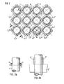
- the corrugated support rods 2, 3, 4 and 5 have a radius of curvature on the shafts which corresponds to the radius R of the outer circumference of the tubes 1. In the case of the thickness of the support rods provided in FIG.
- FIG. 1 initially stands for support rods 2 to 5 with the usual circular cross-section (FIG. 2a), which in the sense of inventing to improve the radial support of the tubes 1 between the support rods and the tubes has a curved, linear contact is present, namely when the support rods intersect in two closely spaced planes and support rods in all spaces between parallel rows of tubes at four circumferentially distributed centering angles ⁇ per tube.
- a firm clamping of the tubes is obtained if the support rods 2 'to 5' have a cross section with parallel side surfaces, for example are flat rods. Then a flat support takes place in each plane of the support rods on the centering angles ⁇ (FIG. 2b).
- the pipes 1 laid according to a square pattern according to FIG. 1 entail that relatively large free flow cross-sections 7 and gusset-shaped flow cross-sections 8 are formed for each holder, which also include increasing thickness of the support rods and smaller pipe distances. These relationships make it possible to optimize the radial support of the pipes at the expense of the flow cross-sections or vice versa.
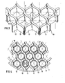
- FIG. 3 shows a so-called wave iron grille, in which the support rods 10, 11 with support rods 12, 13 have a rectangular cross section, that is to say flat rods, and can therefore be arranged in a common plane because they are halved on both sides at the intersection points 14 Penetrate slots 15, 16.
- Fig. 4 shows the wave iron grid according to Fig. 3 with inserted tubes 1 of a tube bundle, which are laid in an equilateral triangle pattern. With this arrangement of tubes, a maximum number of tubes can be accommodated within a tube bundle, which is why this triangular pattern is preferred for reactor vessels.
- the support rods 10 and 11 wrap around each tube at two diametrical centering angles ⁇ 1 , which are supplemented by centering angles ⁇ 2 , which are assigned to the support rods 12 and 13.
- This optimal fixed clamping results from the fact that the thickness of the support rods is approximately equal to the clear distance between adjacent tubes.
- the flow cross-sections within each mounting plane are reduced to the gusset-shaped free spaces 18, which would be sufficient for capacitors, for example.
- Fig. 4 also shows the attachment of the support rods to a ring 17, which in turn is attached to the inner wall of the container shell, not shown.
Landscapes
- Engineering & Computer Science (AREA)
- Physics & Mathematics (AREA)
- Thermal Sciences (AREA)
- Mechanical Engineering (AREA)
- General Engineering & Computer Science (AREA)
- Supports For Pipes And Cables (AREA)
Abstract
Description
Die Erfindung betrifft eine Halterung für die Rohre eines Rohrbündels innerhalb eines Behälters, insbesondere für einen aus Mantel und Rohrbündel bestehenden Wärmeaustauscher oder ein Reaktorgefäß, mit etagenweise angeordneten Stützstäben, die sich durch die Zwischenräume von parallelen Reihen von Rohren erstrecken und die Rohre an ihrem Außenumfang radial abstützend berühren. Die Stützstäbe einer jeden Etage sind dabei üblicherweise an einem Ring befestigt, der das Rohrbündel umgibt und an der Innenwand des Behälters befestigt ist.The invention relates to a holder for the tubes of a tube bundle within a container, in particular for a heat exchanger consisting of jacket and tube bundle or a reactor vessel, with support rods arranged in tiers, which extend through the spaces between parallel rows of tubes and the tubes on their outer circumference radially supportive touch. The support rods of each tier are usually attached to a ring that surrounds the tube bundle and is attached to the inner wall of the container.
Da die Stützstäbe in dem Innenraum des Behälters angeordnet sind, der von einem Medium durchströmt wird, stellen die Stützstäbe einen Strömungswiderstand dar, der einen Druckabfall begründet. Man hat daher die Etagen von geraden Stützstäben, die sich im übrigen etagenweise kreuzen, in größeren Abständen voneinander angeordnet (US 4 127 165). Um einen Druckabfall zu vermindern, wurde gemäß der DE-OS 27 06 049 (= US 4 127 165) vorgeschlagen, in den einzelnen Etagen von Halterungen weniger Stützstäbe vorzusehen, als von den vorhandenen Zwischenräumen zwischen parallelen Reihen von Rohren her angeordnet werden könnten. Dies zwingt aber dazu, mehr Etagen von sich kreuzenden Stützstäben vorzusehen, da jede fehlende radiale Abstützung eines Rohres bei gleichen Abständen der Etagen voneinander die nicht abgestützte, freie Länge von Rohren verdoppelt.Since the support rods are arranged in the interior of the container through which a medium flows, the support rods represent a flow resistance which causes a pressure drop. The levels of straight support bars, which cross each other in stages, have therefore been arranged at greater distances from one another (US Pat. No. 4,127,165). In order to reduce a pressure drop, it was proposed according to DE-OS 27 06 049 (= US 4 127 165) to provide fewer support rods in the individual floors of brackets than could be arranged from the existing spaces between parallel rows of pipes. However, this forces to provide more floors of intersecting support rods, since any lack of radial support for a pipe doubles the unsupported, free length of pipes with the same distances between the floors.
In der US-PS 3 708 142 ist eine Halterung für Rohrbündel beschrieben, bei der jede Etage von geraden Stützstäben aus mehreren sich kreuzenden Stützstäben in dicht beieinanderliegenden Ebenen besteht.US Pat. No. 3,708,142 describes a holder for tube bundles, in which each level of straight support rods consists of a plurality of intersecting support rods in closely spaced planes.
Die Abstützung von Rohren eines Rohrbündels im Behälterbau über ihre Länge hat den Zweck, die von einem zweiten Medium durchströmten Rohre gegen Rißbildung und Bruch zu schützen. Bei einem Wärmeaustauscher steht hier das Schwingungsproblem im Vordergrund, denn durch den Ungleichförmigkeitsgrad von Förderpumpen und die etagenweise Störung der Längsströmung aufgrund der Stützstäbe können in den Rohren schädliche Resonanzschwingungen entstehen. Bei einem Reaktorgefäß sind die Rohre zusätzlich auf Knickung beansprucht, da das die Rohre durchströmende Medium unter hohem Druck steht, der entgegengesetzt gerichtet auf den den Innenraum des Behälters begrenzenden Platten lastet, in denen die Rohre mit ihren Enden befestigt sind.The purpose of supporting tubes of a tube bundle in container construction along their length is to protect the tubes through which a second medium flows against cracking and breakage. In the case of a heat exchanger, the vibration problem is in the foreground, because the degree of non-uniformity of feed pumps and the level disturbance of the longitudinal flow due to the support rods can cause harmful resonance vibrations in the pipes. In a reactor vessel, the tubes are additionally subjected to buckling, since the medium flowing through the tubes is under high pressure, which oppositely loads the plates delimiting the interior of the container, in which the ends of the tubes are fastened.
Alle bekannten Halterungen für die Rohre eines Rohrbündels im Behälterbau verwenden gerade Stützstäbe, die - wenn auch in gitterförmiger, sich kreuzender Anordnung gemäß der US-PS 3 708 142.- die Rohre je nach Stabquerschnitt nur punktförmig oder entlang einer Mantellinie berühren. Eine derartige radiale Abstützung der Rohre an - auf die Rohr-Querschnittsebene bezogen -.dimensionslosen gegenüberliegenden Umfangsteilen muß jedoch als wenig dauerhaft und betriebssicher angesehen werden. Hinzu kommt noch, daß die Rohre hinsichtlich der Schwingungsrichtung und der Richtung einer Ausknickung wegen der Verwendung von geraden Stützstäben gleich welchen Querschnitts große Freiheits- grade haben. Von daher hat sich die Erfindung die Aufgabe gestellt, eine Halterung für die Rohre eines Rohrbündels im Behälterbau zu schaffen, bei der die Rohre innerhalb einer Etage von Stützstäben möglichst wenig Freiheitsgrade in radialer Richtung haben.All known supports for the tubes of a tube bundle in tank just use support rods, which - when the US-
Die Lösung dieser Aufgabe besteht gemäß der Erfindung darin, daß die Stützstäbe einer jeden Etage derart wellenförmig ausgebildet sind, daß sie die Rohre über einen Zentrierwinkel berühren. Hierdurch wird erreicht, daß über den Zentrierwinkel zwischen einem Rohr und einem am Außenumgang des Rohres vorbeigeführten Stützstab zumindest eine Linienberührung quer zu Mantellinien vorliegt, wenn der Stützstab in herkömmlicher Weise einen Rundquerschnitt hat. Diese Linienberührung auf einem Umschlingungswinkel setzt die möglichen Freiheitsgrade des Rohres gegenüber der bisherigen Halterung der Rohre mit geraden Stützstäben mehr oder weniger erheblich herab.The solution to this problem is according to the invention that the support rods of each floor are designed in such a way that they touch the tubes over a centering angle. Hereby is achieved that at least a line contact transverse present on the centering angle between a tube and an over-run on the outside of the pipe handling support rod to surface lines, when the support rod q a round in a conventional manner has uerschnitt. This line contact on a wrap angle more or less significantly reduces the possible degrees of freedom of the pipe compared to the previous mounting of the pipes with straight support rods.
Die radiale Abstützung der Rohre kann gemäß der Erfindung dadurch optimiert werden, daß die Stützstäbe einen Querschnitt mit parallelen Seitenflächen erhalten, die dann eine flächige radiale Abstützung der Rohre auf dem von der Wellenform der Stützstäbe abhängigen Zentrierwinkel begründen.The radial support of the tubes can be optimized according to the invention in that the support rods have a cross section with parallel side surfaces, which then form a flat radial support of the tubes on the centering angle dependent on the waveform of the support rods.
Wenn die erfindungsgemäße Wellenform von Stützstäben runden oder kantigen Querschnitts in Verbindung mit dem an sich bekannten Merkmal von zwei in dicht nebeneinanderliegenden Ebenen angeordneten, sich kreuzenden Gruppen von Stützstäben in jeder Etage angewendet wird, erhält man auf einer kurzen Länge der Rohre eine nahezu umlaufende Abstützung der Rohre über vier umfangsverteilte Zentrierwinkel, d.h. die Rohre sind innerhalb einer jeden Halterung im Sinne der Statistik fest eingespannt, womit sich die Berechnung der Rohre auf Knickung grundsätzlich ändert mit der Folge, daß die Dicke der Rohrwandung durch Verringerung des Außendurchmessers herabgesetzt werden kann, was wiederum die Möglichbietet, mehr Rohre innerhalb eines Rohrbündels vorzusehen. Die feste Einspannung der Rohre innerhalb einer Halterung mit sich kreuzenden Gruppen von gewellten Stützstäben ist natürlich bei Verwendung von hochkant verlegten Flachstäben mit flächiger Abstützung über die Zentrierwinkel wirkungsvoller als bei Verwendung von runden Stäben.If the waveform of support rods of round or angular cross-section in accordance with the invention is used in conjunction with the known feature of two groups of support rods which cross each other and are arranged in closely adjacent planes, an almost all-round support is obtained on a short length of the tubes Pipes over four circumferentially distributed centering angles, ie the pipes are firmly clamped within each holder in the sense of the statistics, whereby the calculation of the pipes on kink changes fundamentally, with the result that the thickness of the pipe wall can be reduced by reducing the outer diameter, which in turn offers the possibility of more pipes within one To provide tube bundle. The firm clamping of the tubes within a holder with intersecting groups of corrugated support rods is of course more effective when using upright laid flat rods with flat support via the centering angle than when using round rods.
Eine am meisten wirkungsvolle feste Einspannung von Rohren über wellenförmige Stützstäbe mit rechteckigem Querschnitt wird dadurch erhalten, daß die Stützstäbe gemäß der weiteren Erfindung in einer gemeinsamen Ebene in Form eines Welleisengitters verlegt sind, indem die Stäbe sich an den Kreuzungsstellen in beiderseits hälftigen Schlitzen durchdringen. Der Ausdruck "Welleisengitter" ist von den bekannten Fußabtretern aus sich kreuzenden gewellten Flachstäben abgeleitet, wie man sie vor Außentüren von Gebäuden verwendet.A most effective fixed clamping of pipes via wave-shaped support rods with a rectangular cross-section is obtained in that the support rods according to the further invention are laid in a common plane in the form of a wave iron grating, in that the rods penetrate in halves on both sides at the intersection points. The term "wave iron grille" is derived from the well-known doormats from intersecting corrugated flat bars, such as those used in front of building exterior doors.
In der Zeichnung sind drei Ausführungsbeispiele von Halterungen für Rohrbündel in Ausschnitten dargestellt, und zwar zeigen:
- Fig. 1 einen Ausschnitt einer Halterung mit in zwei dicht beieinanderliegenden Ebenen verlegten Stützstäben runden oder vierkantigen Querschnittes,
- Fig. 2a und b Querschnitte entlang der Linie II-II in Fig. 1 zur Darstellung verschiedener Stabquerschnitte,
- Fig. 3 ein Welleisengitter in schaubildlicher Darstellung, und
- Fig. 4 einen randseitigen Ausschnitt einer Halterung, bestehend aus einem Welleisengitter nach Fig. 3.
- 1 shows a section of a holder with supporting rods of round or square cross-section laid in two closely spaced planes,
- 2a and b cross sections along the line II-II in Fig. 1 for illustrating various rod cross-sections,
- Fig. 3 is a wave iron grating in a graphical representation, and
- 4 shows an edge-side section of a holder consisting of a wave iron grille according to FIG. 3.
Nach Fig. 1 sind die Rohre 1 eines Rohrbündels im sogenannten quadratischen Muster angeordnet. Durch die Zwischenräume von parallelen Reihen von Rohren, die von links unten bis rechts oben in der Zeichnungsebene geneigt sind, erstrecken sich gewellte Stützstäbe 2, 3, die in einer ersten oberen Ebene liegen. Ebenso erstrecken sich durch Zwischenräume von parallelen Reihen von Rohren, die von rechts unten bis links oben in der Zeichnungsebene ansteigen, gewellte Stützstäbe 4 und 5 in einer dicht unterhalb der ersten Ebene liegenden zweiten Ebene. Die Stützstäbe liegen somit an den Kreuzungsstellen 6 dicht untereinander. Die gewellten Stützstäbe 2, 3, 4 und 5 haben an den Wellen einen Krümmungsradius, der dem Radius R des Außenumfanges der Rohre 1 entspricht. Bei der in Fig. 1 vorgesehenen Dicke der Stützstäbe umschlingen diese je für sich die Rohre auf einem Zentrierwinkel α und zwar unter Berücksichtigung des sich kreuzenden Verlaufes der Stützstäbe an vier umfangsverteilten Zentrierwinkeln . Je größer die Dicke der Stützstäbe ist, um so größer wird der Zentrier- bzw. Umschlingungswinkel α. Dies trifft auch zu, wenn bei geringerer Dicke der Stützstäbe 2 bis 5 die Abstände der Rohre 1 voneinander verringert werden, so daß innerhalb eines Rohrbündels mehr Rohre verlegt werden können.1, the tubes 1 of a tube bundle are arranged in the so-called square pattern.
) Das Ausführungsbeispiel nach Fig. 1 steht zunächst für Stützstäbe 2 bis 5 mit üblichem kreisrunden Querschnitt (Fig. 2a), wodurch bereits im Sinne der Erfindurig_zur Verbesserung der radialen Abstützung der Rohre 1 zwischen den Stützstäben und den Rohren eine gebogene linienförmige Be-5 rührung vorliegt, und zwar bei sich kreuzender Anordnung der Stützstäbe in zwei dicht beieinanderliegenden Ebenen und Stützstäben in allen Zwischenräumen zwischen parallelen Reihen von Rohren an vier umfangsverteilten Zentrierwinkeln α pro Rohr. Eine feste Einspannung der Rohre erhält man, wenn die Stützstäbe 2' bis 5' einen Querschnitt mitparallelen Seitenflächen haben, beispielsweise Flachstäbe sind. Dann findet in jeder Ebene der Stützstäbe auf den Zentrierwinkeln α eine flächige Abstützung statt (Fig. 2b).) The embodiment according to FIG. 1 initially stands for support rods 2 to 5 with the usual circular cross-section (FIG. 2a), which in the sense of inventing to improve the radial support of the tubes 1 between the support rods and the tubes has a curved, linear contact is present, namely when the support rods intersect in two closely spaced planes and support rods in all spaces between parallel rows of tubes at four circumferentially distributed centering angles α per tube. A firm clamping of the tubes is obtained if the support rods 2 'to 5' have a cross section with parallel side surfaces, for example are flat rods. Then a flat support takes place in each plane of the support rods on the centering angles α (FIG. 2b).
5 Die nach einem quadratischen Muster verlegten Rohre 1 gemäß Fig. 1 bringen es mit sich, daß für jede Halterung relativ große freie Durchstömquerschnitte 7 sowie zwickelförmige Durchströmquerschnitte 8 entstehen, die mit zunehmender Dicke der Stützstäbe sowie kleineren Rohrabständen kleiner werden. Über diese Zusammenhänge hat man es in der Hand, die radiale Abstützung der Rohre auf Kosten der Durchströmquerschnitte zu optimieren oder umgekehrt. 5 The pipes 1 laid according to a square pattern according to FIG. 1 entail that relatively large free flow cross-sections 7 and gusset-shaped flow cross-sections 8 are formed for each holder, which also include increasing thickness of the support rods and smaller pipe distances. These relationships make it possible to optimize the radial support of the pipes at the expense of the flow cross-sections or vice versa.
In Fig. 3 erkennt man ein sogenanntes Welleisengitter, bei dem die Stützstäbe 10,11 mit Stützstäben 12, 13 rechteckigen Querschnitt haben, also Flachstäbe sind, und deshalb in einer gemeinsamen Ebene angeordnet werden können, weil sie sich an den Kreuzungsstellen 14 in beiderseits hälftigen Schlitzen 15, 16 durchdringen. Fig. 4 zeigt das Welleisengitter nach Fig. 3 mit eingesetzten Rohren 1 eines Rohrbündels, die in einem gleichseitigen Dreiecksmuster verlegt sind. Mit dieser Anordnung von Rohren sind innerhalb eines Rohrbündels eine Höchstzahl von Rohren unterzubringen, weshalb dieses Dreiecksmuster für Reaktorgefäße bevorzugt wird.3 shows a so-called wave iron grille, in which the support rods 10, 11 with
Wie Fig. 4 zeigt, umschlingen die Stützstäbe 10 und 11 ein jedes Rohr auf zwei diametralen Zentrierwinkeln α1, die ergänzt werden durch Zentrierwinkel α2 , die den Stützstäben 12 und 13 zugeordnet sind. Damit ist jedes-Rohr bei dem Ausführungsbeispiel einer Halterung nach Fig. 3 und 4 auf der Höhe der Stützstäbe über jeweils einen Gesamt-Zentrierwinkel α1 + α2 = 240° flächig abgestützt, d.h. fest eingespannt. Diese optimale feste Einspannung ergibt sich daraus, daß die Dicke der Stützstäbe etwa gleich dem lichten Abstand zwischen benachbarten Rohren ist. Mit der Optimierung der festen Einspannung der Rohre im Sinne des I Ausführungsbeispiels nach Fig. 3 und 4 geht allerdings einher die Verringerung der Durchströmquerschnitte innerhalb einer jeden Halterungsebene auf die zwickelförmigen Freiräume 18, die beispielsweise bei Kondensatoren ausreichend wären.As shown in FIG. 4, the
Fig. 4 zeigt übrigens noch die Befestigung der Stützstäbe an einem Ring 17, der seinerseits an der Innenwandung des nicht dargestellten Behältermantels befestigt wird.Fig. 4 also shows the attachment of the support rods to a
Claims (4)
Priority Applications (1)
| Application Number | Priority Date | Filing Date | Title |
|---|---|---|---|
| EP82109265A EP0105938A1 (en) | 1982-10-07 | 1982-10-07 | Support for tubes of a tube bundle inside a vessel |
Applications Claiming Priority (1)
| Application Number | Priority Date | Filing Date | Title |
|---|---|---|---|
| EP82109265A EP0105938A1 (en) | 1982-10-07 | 1982-10-07 | Support for tubes of a tube bundle inside a vessel |
Publications (1)
| Publication Number | Publication Date |
|---|---|
| EP0105938A1 true EP0105938A1 (en) | 1984-04-25 |
Family
ID=8189261
Family Applications (1)
| Application Number | Title | Priority Date | Filing Date |
|---|---|---|---|
| EP82109265A Withdrawn EP0105938A1 (en) | 1982-10-07 | 1982-10-07 | Support for tubes of a tube bundle inside a vessel |
Country Status (1)
| Country | Link |
|---|---|
| EP (1) | EP0105938A1 (en) |
Cited By (4)
| Publication number | Priority date | Publication date | Assignee | Title |
|---|---|---|---|---|
| US5033542A (en) * | 1989-02-28 | 1991-07-23 | Mtu Motoren-Und Turbinen-Union | Spacer supports for tubes of a matrix of a heat exchanger |
| US5449037A (en) * | 1993-12-08 | 1995-09-12 | Brown Fintube Corporation | Heat exchanger tube spacer, separator, and support |
| US20170321971A1 (en) * | 2014-12-30 | 2017-11-09 | Joint Stock Company "Akme-Engineering" | Heat Exchanger Tube Spacing Device (Varinats) |
| WO2022147070A1 (en) * | 2020-12-30 | 2022-07-07 | Scientific Design Company, Inc. | Corrugated grid support for vertical boiling reactor |
Citations (5)
| Publication number | Priority date | Publication date | Assignee | Title |
|---|---|---|---|---|
| GB1101953A (en) * | 1964-10-20 | 1968-02-07 | Babcock & Wilcox Co | Improvements in or relating to rod, pin and tube assemblies |
| GB1223045A (en) * | 1967-07-31 | 1971-02-17 | Alcatel S A Soc | Suppression of vibrations in tubes |
| DE2045353A1 (en) * | 1969-09-26 | 1971-04-15 | Waagner Biro AG, Wien | Shell and tube heat exchanger |
| DE2052837A1 (en) * | 1970-10-21 | 1972-04-27 | Frank W | Heat exchanger tube fixing - comprises flexible tubes transversely between rows of exchanger tubes |
| FR2130384A1 (en) * | 1971-03-19 | 1972-11-03 | Ca Atomic Energy Ltd |
-
1982
- 1982-10-07 EP EP82109265A patent/EP0105938A1/en not_active Withdrawn
Patent Citations (5)
| Publication number | Priority date | Publication date | Assignee | Title |
|---|---|---|---|---|
| GB1101953A (en) * | 1964-10-20 | 1968-02-07 | Babcock & Wilcox Co | Improvements in or relating to rod, pin and tube assemblies |
| GB1223045A (en) * | 1967-07-31 | 1971-02-17 | Alcatel S A Soc | Suppression of vibrations in tubes |
| DE2045353A1 (en) * | 1969-09-26 | 1971-04-15 | Waagner Biro AG, Wien | Shell and tube heat exchanger |
| DE2052837A1 (en) * | 1970-10-21 | 1972-04-27 | Frank W | Heat exchanger tube fixing - comprises flexible tubes transversely between rows of exchanger tubes |
| FR2130384A1 (en) * | 1971-03-19 | 1972-11-03 | Ca Atomic Energy Ltd |
Cited By (7)
| Publication number | Priority date | Publication date | Assignee | Title |
|---|---|---|---|---|
| US5033542A (en) * | 1989-02-28 | 1991-07-23 | Mtu Motoren-Und Turbinen-Union | Spacer supports for tubes of a matrix of a heat exchanger |
| US5449037A (en) * | 1993-12-08 | 1995-09-12 | Brown Fintube Corporation | Heat exchanger tube spacer, separator, and support |
| US20170321971A1 (en) * | 2014-12-30 | 2017-11-09 | Joint Stock Company "Akme-Engineering" | Heat Exchanger Tube Spacing Device (Varinats) |
| US10563929B2 (en) * | 2014-12-30 | 2020-02-18 | Joint Stock Company “Akme-Engineering” | Heat exchanger tube spacing device (varinats) |
| WO2022147070A1 (en) * | 2020-12-30 | 2022-07-07 | Scientific Design Company, Inc. | Corrugated grid support for vertical boiling reactor |
| US12030028B2 (en) | 2020-12-30 | 2024-07-09 | Scientific Design Company, Inc. | Corrugated grid support for vertical boiling reactor |
| EP4271957A4 (en) * | 2020-12-30 | 2024-09-04 | Scient Design Llc | Corrugated grid support for vertical boiling reactor |
Similar Documents
| Publication | Publication Date | Title |
|---|---|---|
| DE2707702C2 (en) | Support device for a plurality of tubes in a heat exchanger | |
| EP0517750B1 (en) | Boiling water nuclear reactor and fuel element therefor | |
| DE2601645A1 (en) | HEAT EXCHANGER | |
| DE2045353B2 (en) | PIPE HEAT EXCHANGER | |
| DE2316133C2 (en) | Shell and tube heat exchanger | |
| CH477666A (en) | Heat exchanger | |
| DE1924462C3 (en) | Pressure vessel | |
| DE1939564A1 (en) | Suspension system for multiple pipe arrangements, especially in heat exchangers of nuclear reactors | |
| EP0105938A1 (en) | Support for tubes of a tube bundle inside a vessel | |
| DE1439775A1 (en) | Fuel rod bundles for nuclear reactors | |
| DE2550035C3 (en) | Heat exchanger with a plurality of heat exchange medium flow tubes arranged at a distance from one another | |
| DE2804113A1 (en) | BRACKET FOR FASTENING THE TUBES OF A HEAT EXCHANGER | |
| DE3219297C2 (en) | Heat exchangers, in particular hot gas coolers for helium | |
| DE2459472B1 (en) | GAS HEATED STEAM GENERATOR, IN PARTICULAR FOR NUCLEAR REACTOR PLANTS | |
| DE3008456C2 (en) | ||
| DE2706049C2 (en) | Device for storing a plurality of tubes in a heat exchanger | |
| CH632583A5 (en) | PIPE BUNDLE FOR HEAT TRANSFER THROUGH TOUCH. | |
| DE2541399C2 (en) | Shell and tube heat exchanger | |
| DE2308317C3 (en) | Large size heat exchangers for operation at high temperatures and pressures | |
| DE2734060C2 (en) | Heat exchanger with a tube bundle made up of a large number of helically coiled tubes | |
| DE1960965C3 (en) | Tubular heat exchangers for liquids with a tendency to scale or deposits | |
| DE2129809A1 (en) | Boiling water reactor core | |
| DE1108715B (en) | Pipe support for pipe bundles of heat exchangers | |
| DE1806432C3 (en) | Spacer grid for a nuclear reactor fuel element | |
| DE1514993C3 (en) | Nuclear reactor fuel assembly with a bundle of parallel fuel rods |
Legal Events
| Date | Code | Title | Description |
|---|---|---|---|
| PUAI | Public reference made under article 153(3) epc to a published international application that has entered the european phase |
Free format text: ORIGINAL CODE: 0009012 |
|
| AK | Designated contracting states |
Designated state(s): AT BE DE FR GB IT NL SE |
|
| STAA | Information on the status of an ep patent application or granted ep patent |
Free format text: STATUS: THE APPLICATION IS DEEMED TO BE WITHDRAWN |
|
| 18D | Application deemed to be withdrawn |
Effective date: 19850325 |
|
| RIN1 | Information on inventor provided before grant (corrected) |
Inventor name: LEFFER, HANS GEORG, DIPL.-ING. |