EP0105533B1 - Dispositif d'homogénéisation et d'amélioration de l'alimentation des moteurs à carburateur - Google Patents
Dispositif d'homogénéisation et d'amélioration de l'alimentation des moteurs à carburateur Download PDFInfo
- Publication number
- EP0105533B1 EP0105533B1 EP83200756A EP83200756A EP0105533B1 EP 0105533 B1 EP0105533 B1 EP 0105533B1 EP 83200756 A EP83200756 A EP 83200756A EP 83200756 A EP83200756 A EP 83200756A EP 0105533 B1 EP0105533 B1 EP 0105533B1
- Authority
- EP
- European Patent Office
- Prior art keywords
- ball bearing
- turbine
- flow
- flange
- blades
- Prior art date
- Legal status (The legal status is an assumption and is not a legal conclusion. Google has not performed a legal analysis and makes no representation as to the accuracy of the status listed.)
- Expired - Lifetime
Links
- 238000000265 homogenisation Methods 0.000 title claims description 6
- 239000000203 mixture Substances 0.000 claims description 26
- 230000002093 peripheral effect Effects 0.000 claims description 4
- 239000003502 gasoline Substances 0.000 claims description 2
- 239000000446 fuel Substances 0.000 description 16
- 239000007789 gas Substances 0.000 description 8
- 239000004519 grease Substances 0.000 description 2
- 230000001133 acceleration Effects 0.000 description 1
- 230000001154 acute effect Effects 0.000 description 1
- 238000002485 combustion reaction Methods 0.000 description 1
- 230000007423 decrease Effects 0.000 description 1
- 239000002737 fuel gas Substances 0.000 description 1
- 238000009434 installation Methods 0.000 description 1
- 239000003595 mist Substances 0.000 description 1
- 238000002156 mixing Methods 0.000 description 1
- 238000012986 modification Methods 0.000 description 1
- 230000004048 modification Effects 0.000 description 1
- 230000003071 parasitic effect Effects 0.000 description 1
Images
Classifications
-
- G—PHYSICS
- G01—MEASURING; TESTING
- G01L—MEASURING FORCE, STRESS, TORQUE, WORK, MECHANICAL POWER, MECHANICAL EFFICIENCY, OR FLUID PRESSURE
- G01L23/00—Devices or apparatus for measuring or indicating or recording rapid changes, such as oscillations, in the pressure of steam, gas, or liquid; Indicators for determining work or energy of steam, internal-combustion, or other fluid-pressure engines from the condition of the working fluid
- G01L23/24—Devices or apparatus for measuring or indicating or recording rapid changes, such as oscillations, in the pressure of steam, gas, or liquid; Indicators for determining work or energy of steam, internal-combustion, or other fluid-pressure engines from the condition of the working fluid specially adapted for measuring pressure in inlet or exhaust ducts of internal-combustion engines
-
- F—MECHANICAL ENGINEERING; LIGHTING; HEATING; WEAPONS; BLASTING
- F02—COMBUSTION ENGINES; HOT-GAS OR COMBUSTION-PRODUCT ENGINE PLANTS
- F02M—SUPPLYING COMBUSTION ENGINES IN GENERAL WITH COMBUSTIBLE MIXTURES OR CONSTITUENTS THEREOF
- F02M23/00—Apparatus for adding secondary air to fuel-air mixture
- F02M23/04—Apparatus for adding secondary air to fuel-air mixture with automatic control
- F02M23/08—Apparatus for adding secondary air to fuel-air mixture with automatic control dependent on pressure in main combustion-air induction system, e.g. pneumatic-type apparatus
- F02M23/09—Apparatus for adding secondary air to fuel-air mixture with automatic control dependent on pressure in main combustion-air induction system, e.g. pneumatic-type apparatus using valves directly opened by low pressure
-
- F—MECHANICAL ENGINEERING; LIGHTING; HEATING; WEAPONS; BLASTING
- F02—COMBUSTION ENGINES; HOT-GAS OR COMBUSTION-PRODUCT ENGINE PLANTS
- F02M—SUPPLYING COMBUSTION ENGINES IN GENERAL WITH COMBUSTIBLE MIXTURES OR CONSTITUENTS THEREOF
- F02M29/00—Apparatus for re-atomising condensed fuel or homogenising fuel-air mixture
- F02M29/02—Apparatus for re-atomising condensed fuel or homogenising fuel-air mixture having rotary parts, e.g. fan wheels
-
- F—MECHANICAL ENGINEERING; LIGHTING; HEATING; WEAPONS; BLASTING
- F02—COMBUSTION ENGINES; HOT-GAS OR COMBUSTION-PRODUCT ENGINE PLANTS
- F02M—SUPPLYING COMBUSTION ENGINES IN GENERAL WITH COMBUSTIBLE MIXTURES OR CONSTITUENTS THEREOF
- F02M3/00—Idling devices for carburettors
- F02M3/02—Preventing flow of idling fuel
- F02M3/04—Preventing flow of idling fuel under conditions where engine is driven instead of driving, e.g. driven by vehicle running down hill
- F02M3/045—Control of valves situated in the idling nozzle system, or the passage system, by electrical means or by a combination of electrical means with fluidic or mechanical means
-
- F—MECHANICAL ENGINEERING; LIGHTING; HEATING; WEAPONS; BLASTING
- F02—COMBUSTION ENGINES; HOT-GAS OR COMBUSTION-PRODUCT ENGINE PLANTS
- F02M—SUPPLYING COMBUSTION ENGINES IN GENERAL WITH COMBUSTIBLE MIXTURES OR CONSTITUENTS THEREOF
- F02M7/00—Carburettors with means for influencing, e.g. enriching or keeping constant, fuel/air ratio of charge under varying conditions
- F02M7/10—Other installations, without moving parts, for influencing fuel/air ratio, e.g. electrical means
- F02M7/11—Altering float-chamber pressure
-
- F—MECHANICAL ENGINEERING; LIGHTING; HEATING; WEAPONS; BLASTING
- F02—COMBUSTION ENGINES; HOT-GAS OR COMBUSTION-PRODUCT ENGINE PLANTS
- F02M—SUPPLYING COMBUSTION ENGINES IN GENERAL WITH COMBUSTIBLE MIXTURES OR CONSTITUENTS THEREOF
- F02M7/00—Carburettors with means for influencing, e.g. enriching or keeping constant, fuel/air ratio of charge under varying conditions
- F02M7/12—Other installations, with moving parts, for influencing fuel/air ratio, e.g. having valves
- F02M7/18—Other installations, with moving parts, for influencing fuel/air ratio, e.g. having valves with means for controlling cross-sectional area of fuel-metering orifice
- F02M7/20—Other installations, with moving parts, for influencing fuel/air ratio, e.g. having valves with means for controlling cross-sectional area of fuel-metering orifice operated automatically, e.g. dependent on altitude
-
- Y—GENERAL TAGGING OF NEW TECHNOLOGICAL DEVELOPMENTS; GENERAL TAGGING OF CROSS-SECTIONAL TECHNOLOGIES SPANNING OVER SEVERAL SECTIONS OF THE IPC; TECHNICAL SUBJECTS COVERED BY FORMER USPC CROSS-REFERENCE ART COLLECTIONS [XRACs] AND DIGESTS
- Y02—TECHNOLOGIES OR APPLICATIONS FOR MITIGATION OR ADAPTATION AGAINST CLIMATE CHANGE
- Y02T—CLIMATE CHANGE MITIGATION TECHNOLOGIES RELATED TO TRANSPORTATION
- Y02T10/00—Road transport of goods or passengers
- Y02T10/10—Internal combustion engine [ICE] based vehicles
- Y02T10/12—Improving ICE efficiencies
Definitions
- the present invention relates to a device for homogenizing and improving the supply of engines with carburetors, intended to be placed between the carburetor and the intake manifold of an engine.
- the homogenization device is used in particular with a carburetion corrector to act during periods of acceleration and deceleration of the engine, by admitting additional air or exhaust gas, crankcase gas or a mixture of these gases, downstream of the carburetor.
- French patent FR-A 698 512 describes a charge mixer for an internal combustion engine. This consists of one (or more) fan blades supported by an outer peripheral ball bearing. This device which can be associated with a trellis cutting the passage section of the fuel flow is specially adapted to obtain vigorous mixing of the fuel mixture admitted into the engine. More specifically, this charge mixer is arranged on a particular pipe connecting the intake manifold to the carburetor.
- the fins provided in this mixer are not located inside a skirt and have a large incidence with respect to the flow, the geometric projection of the fins in the direction of the flow of the fuel mixture covering almost completely the section of the pipe, which inevitably generates annoying pressure losses for an application on modern engines and which disturbs the Laws of automaticity of the carburetor.
- the document FR-A-2 385 028 describes a propeller mounted madly on an axis, the inertia of which is capable of preventing the backflow of fresh fuel gas, in the low and medium revs of an engine consecutive to the importance of the fixed adjustment dimension of the Delay in Closing the Inlet Valve (RFA dimension).
- the document FR-A-746656 describes a device which comprises two rotary elements rotating in opposite directions which inevitably create a disordered turbulence of the air-petrol mixture with a beat whose frequency is a function of the speed of the two elements which is different.
- the device has two ball bearings which with the two turbines increases the thickness of the device and makes it difficult to insert between the carburetor and the intake manifold of a modern engine due to space problems (closing the engine cover and significant change in the kinematics of the throttle valve control) carburetor).
- the rectangular shaped fins have a recess in a smaller rectangle at the root of the bearing. They have a leading edge and a straight trailing edge which pass very close to the plane of the flange. It follows that the device is not insertable between the manifold and the carburetor of a modern engine without the presence of a sleeve or flange to allow the movement of the throttle valve, which in the open position greatly exceeds the carburetor flange plane.
- the fins protrude but very slightly from the thickness of the ball bearing, but not from the thickness of the flange, and they do not penetrate into the engine's intake manifold.
- the internal bore of the ball bearing does not consist of a nozzle; it is only a succession of two normal internal crowns of the two separate ball bearings.
- the fins converge well towards the center without reaching it, but by creating by their shape and their arrangement a central node of important disturbances in the flow of the fuel mixture.
- Document US-A 1823818 relates to the invention of a carburetor which comprises a rotary element with fins and a peripheral ball bearing.
- This element is embedded at the outlet of the carburetor and is intended to homogenize the air / petrol mixture.
- the fins seen in plan, have the shape of small elongated right triangles. They are distributed and fixed by the short side of the triangle, around the internal bore of the ball bearing. They converge towards the center of the bearing where they are joined together at this level by their most acute angle of their triangular shape. The depth of the fins slightly exceeds the thickness of the ball bearing, but only towards the inside of the carburetor.
- the profile of the fins has substantially the shape of a square at right angles, one side is parallel to the direction of flow of the fuel mixture and the other side is perpendicular to this direction the stuffing of the flow in the folding of angle of the fin above all creates the torque.
- Document DE-A-2001299 corresponding to document FR-A-2 028 410 describes a gasifier made up of several fins distributed and fixed around an extended ring of a sleeve. It is placed at the inlet or outlet of the carburetor, or in the body of the carburetor. Each fin has the shape of a right triangle, the hypotenuse of which is slightly curved towards the outside of the triangle. The longest side of the right angle is located on the inner periphery of the sleeve with an incidence whose recommended value is very wide: 15 ° to 60 ° depending on the speed at which you want to use the engine. The shortest side of the right angle of the right triangle, perpendicular to the air flow, constitutes the leading edge of the fin which exactly coincides with the plane of the circular entry of the sleeve ring .
- the thickness of the fin profile thins towards the trailing edge, that is to say towards the hypotenuse of the triangle (Fig. 2 of the document). After passing through these fins, the gas mixture is finely atomized in the form of a mist.
- the present invention now proposes an improved homogenization device which is sensitive to the low speeds of carburettor engines and well suited to all the operating conditions of these engines, without this homogenization leading to troublesome pressure losses for the development of the maximum power of said motors.
- the present invention aims to obtain a good distribution of the fuel mixture in the intake pipes of the engine with reduction of parasitic phenomena of "double suction" at the nozzles of the carburetor.
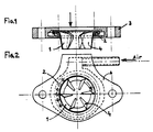
- the present invention provides a device for homogenizing the fuel mixture of the engines comprising an axial turbine with a single stage constituted by a wheel (1) with several fins (4), centered inside a bearing with balls (2) housed in a flange (3) placed downstream of the carburetor so that only the fins are in the flow of the fuel mixture which drives the turbine, the fins converging towards the axis of rotation without reaching it, their interior ends being free, characterized in that the inertia in rotation of the turbine and ball bearing assembly is sufficient to absorb the fluctuations in the speed of the fuel mixture, in order to improve the distribution of the fuel mixture in the intake manifolds of the engine and to limit the phenomena of double-suction of the petrol at the level of the carburetor, in that the fins (4) of the turbine (1) have a low stall incidence and are located on the for inner turn of a skirt forming a nozzle which is linked to the internal crown of the ball bearing (2), in that the nozzle overflows, with the fins beyond the
- the peripheral ball bearing (2) forms a thrust ball bearing in the direction of flow of the fuel mixture and a sliding plate bearing in the other direction, and is provided for this purpose with a crown constituting on one side the raceway of the balls and on the other side the movable sliding plate, the fixed sliding plate being formed by the bottom of a recess formed in the flange (3) to form the fixed cup of the ball bearing.
- the turbine flange homogenization shown in Figures 1 and 2 is used in particular in combination with the correction device described in European patent No. 0 026 198 to improve the effectiveness of this correction system and comprises in this case a additional air intake circuit shown in Figure 2.
- the air or the carburetor correction gas passes through the flange and the inter-ball spaces of the bearing to cool the latter and possibly grease it: case air and crankcase gas intake.
- the flange shown in Figures 1 and 2 is intended to be placed between the carburetor and the engine intake manifold.
- This flange is characterized in that the turbine is centered in the flange by means of a ball bearing preferably of the thrust bearing type, housed entirely in the flange. By this arrangement, only the turbine is in the flow of the fuel mixture supplied by the carburetor.
- the turbine and the movable part of the ball bearing have a certain inertia in rotation sufficient to dampen the speed fluctuations of the gas-air-gas stream, in order to limit the phenomenon of double-suction of the gasoline at the level of the carburetor and d '' improve the distribution of the fuel mixture in the engine intake manifolds.
- Figures 1 and 2 show that the turbine is made up of several fins whose depth (distance in the direction of flow from the leading edge to the trailing edge) extends beyond the thickness of the ball bearing and the flange.
- This overflow of the fins beyond the thickness of the bearing and of the flange is a particular characteristic since the flange must have a reduced thickness so that its installation on a modern vehicle engine does not cause any annoying modifications.
- the fins must necessarily overflow beyond the thickness of the ball bearing and the flange, as indicated in FIG. 1, the depth of the fins is important in particular towards their rooting because of the speed "brush" narrow that generates the throttle when it is towards the closed positions.
- Figures 1 and 2 show that the fins shown converge towards the center of the ball bearing, but without reaching it, with their rounded end. The incidence of fins is low.
- the ball bearing is preferably of the thrust bearing type with a single row of balls ( Figure 1). It has the particularity of being a thrust ball bearing in the direction of flow of the fuel mixture and a sliding plate bearing in the other direction.
Landscapes
- Engineering & Computer Science (AREA)
- Chemical & Material Sciences (AREA)
- Combustion & Propulsion (AREA)
- Mechanical Engineering (AREA)
- General Engineering & Computer Science (AREA)
- Physics & Mathematics (AREA)
- General Physics & Mathematics (AREA)
- Control Of Throttle Valves Provided In The Intake System Or In The Exhaust System (AREA)
- Rolling Contact Bearings (AREA)
- Supercharger (AREA)
- Engine Equipment That Uses Special Cycles (AREA)
Applications Claiming Priority (2)
| Application Number | Priority Date | Filing Date | Title |
|---|---|---|---|
| FR7909259A FR2453981A1 (fr) | 1979-04-12 | 1979-04-12 | Dispositif correcteur de carburation des moteurs d'automobiles pour les phases de fonctionnement transitoires |
| FR7909259 | 1979-04-12 |
Related Parent Applications (1)
| Application Number | Title | Priority Date | Filing Date |
|---|---|---|---|
| EP80900679.4 Division | 1980-04-14 |
Publications (2)
| Publication Number | Publication Date |
|---|---|
| EP0105533A1 EP0105533A1 (fr) | 1984-04-18 |
| EP0105533B1 true EP0105533B1 (fr) | 1991-03-20 |
Family
ID=9224250
Family Applications (2)
| Application Number | Title | Priority Date | Filing Date |
|---|---|---|---|
| EP83200756A Expired - Lifetime EP0105533B1 (fr) | 1979-04-12 | 1980-04-14 | Dispositif d'homogénéisation et d'amélioration de l'alimentation des moteurs à carburateur |
| EP80900679A Expired EP0026198B1 (fr) | 1979-04-12 | 1980-10-23 | Dispositif correcteur de carburation des moteurs de vehicules en phases de fonctionnement transitoires |
Family Applications After (1)
| Application Number | Title | Priority Date | Filing Date |
|---|---|---|---|
| EP80900679A Expired EP0026198B1 (fr) | 1979-04-12 | 1980-10-23 | Dispositif correcteur de carburation des moteurs de vehicules en phases de fonctionnement transitoires |
Country Status (4)
| Country | Link |
|---|---|
| EP (2) | EP0105533B1 (OSRAM) |
| DE (2) | DE3071498D1 (OSRAM) |
| FR (1) | FR2453981A1 (OSRAM) |
| WO (1) | WO1980002179A1 (OSRAM) |
Families Citing this family (3)
| Publication number | Priority date | Publication date | Assignee | Title |
|---|---|---|---|---|
| FR2453981A1 (fr) * | 1979-04-12 | 1980-11-07 | Mandar Andre | Dispositif correcteur de carburation des moteurs d'automobiles pour les phases de fonctionnement transitoires |
| GB2142383A (en) * | 1983-06-30 | 1985-01-16 | Dei Lai Min | Carburettor with overrunning air supply to the idling system |
| GB2321084B (en) * | 1997-01-09 | 2000-05-10 | Brian Wilcockson | Charge mixing device for the intake of an i.c. engine |
Citations (1)
| Publication number | Priority date | Publication date | Assignee | Title |
|---|---|---|---|---|
| FR2453981A1 (fr) * | 1979-04-12 | 1980-11-07 | Mandar Andre | Dispositif correcteur de carburation des moteurs d'automobiles pour les phases de fonctionnement transitoires |
Family Cites Families (20)
| Publication number | Priority date | Publication date | Assignee | Title |
|---|---|---|---|---|
| US1389909A (en) * | 1921-09-06 | Indicator | ||
| FR427114A (fr) * | 1910-05-19 | 1911-07-27 | Marius Berliet | Limitateur de vitesse applicable aux moteurs à explosions |
| FR483481A (fr) * | 1916-01-06 | 1917-07-11 | Automatic Carburetor Company | Dispositif pour modifier automatiquement la formation du combustible dans les moteurs à explosions |
| GB182120A (en) * | 1921-06-23 | 1923-01-04 | Minot Olsen And Thurber Inc | Improvements in auxiliary air inlets for the intake manifolds of internal combustionengines |
| US1858835A (en) * | 1923-12-31 | 1932-05-17 | Bendix Stromberg Carbureter Co | Carburetor |
| US1823818A (en) * | 1926-03-19 | 1931-09-15 | Constantin Cesar Jean | Carburetor |
| GB305338A (en) * | 1927-12-23 | 1929-02-07 | Francis Henry Paton Beatson | Improvements in and relating to mixture supply systems of internal combustion engines |
| FR698512A (fr) * | 1930-01-20 | 1931-01-31 | Mélangeur de charge perfectionné pour moteurs à combustion interne | |
| FR746656A (fr) * | 1932-12-01 | 1933-06-02 | Dispositif d'homogénéisation pour moteurs à explosions | |
| GB519242A (en) * | 1937-10-11 | 1940-03-20 | Bosch Gmbh Robert | Improvements in or relating to auxiliary air admission devices for internal combustion engines |
| FR1478467A (fr) * | 1966-02-28 | 1967-04-28 | Perfectionnement aux systèmes de commande des circuits d'enrichissement et des circuits d'économie dans les carburateurs ou systèmes de carburation | |
| FR1525059A (fr) * | 1966-12-09 | 1968-05-17 | Nippon Denso Company | Clapet de commande permettant d'éviter une combustion explosive dans le tuyau d'échappement d'un moteur à combustion interne |
| US3470855A (en) * | 1967-06-26 | 1969-10-07 | Ernest A Von Seggern | Air valve actuating means and method for supplying auxiliary air to an internal combustion engine |
| ES362590A1 (es) * | 1969-01-16 | 1970-11-16 | Joan Claret | Perfeccionamientos en los medios gasificadores para motoresde explosion. |
| US3937202A (en) * | 1974-01-21 | 1976-02-10 | Mobil Oil Corporation | Economy driving aid |
| IT1023750B (it) * | 1974-09-19 | 1978-05-30 | Chicocini R | Dispositivo di controllo della erogazione di propellente liquido o gassoso per motori a combustione interna in specie destinati alla autotrazione |
| CH620275A5 (en) * | 1976-05-07 | 1980-11-14 | Bosch Gmbh Robert | Device for more reliable switching of solenoid valves for overrun cut-off in carburettors |
| FR2376948A2 (fr) * | 1977-01-05 | 1978-08-04 | Mayer Ferdy | Procede et dispositif pour ameliorer la consommation de carburant des vehicules |
| FR2385028A1 (fr) * | 1977-03-25 | 1978-10-20 | Saint Martin Francois | Helice livre anti refoulement |
| US4166382A (en) * | 1978-03-27 | 1979-09-04 | Petersen Paul S | Auto economy gauge |
-
1979
- 1979-04-12 FR FR7909259A patent/FR2453981A1/fr active Granted
-
1980
- 1980-04-14 WO PCT/FR1980/000058 patent/WO1980002179A1/fr not_active Ceased
- 1980-04-14 DE DE8080900679T patent/DE3071498D1/de not_active Expired
- 1980-04-14 EP EP83200756A patent/EP0105533B1/fr not_active Expired - Lifetime
- 1980-04-14 DE DE8383200756T patent/DE3072192D1/de not_active Expired - Lifetime
- 1980-10-23 EP EP80900679A patent/EP0026198B1/fr not_active Expired
Patent Citations (1)
| Publication number | Priority date | Publication date | Assignee | Title |
|---|---|---|---|---|
| FR2453981A1 (fr) * | 1979-04-12 | 1980-11-07 | Mandar Andre | Dispositif correcteur de carburation des moteurs d'automobiles pour les phases de fonctionnement transitoires |
Also Published As
| Publication number | Publication date |
|---|---|
| FR2453981A1 (fr) | 1980-11-07 |
| WO1980002179A1 (fr) | 1980-10-16 |
| DE3072192D1 (de) | 1991-04-25 |
| FR2453981B3 (OSRAM) | 1982-01-15 |
| EP0026198B1 (fr) | 1986-03-19 |
| EP0105533A1 (fr) | 1984-04-18 |
| DE3071498D1 (en) | 1986-04-24 |
| EP0026198A1 (fr) | 1981-04-08 |
Similar Documents
| Publication | Publication Date | Title |
|---|---|---|
| CA2732127A1 (fr) | Dispositif de reduction de bruit pour nacelle de turboreacteur a chevrons mobiles, et nacelle associee | |
| FR2880391A1 (fr) | Diffuseur pour chambre annulaire de combustion, en particulier pour un turbomoteur d'avion | |
| EP0105533B1 (fr) | Dispositif d'homogénéisation et d'amélioration de l'alimentation des moteurs à carburateur | |
| FR2463289A1 (fr) | Systeme de carburateur a rotor avec formation du melange de ralenti pour les moteurs a combustion interne | |
| FR3067387B1 (fr) | Ecope d'alimentation en air pour l'alimentation d'un systeme de refroidissement et de controle des jeux d'une turbine | |
| CA2721227A1 (fr) | Turbomoteur a double flux pour aeronef a emission de bruit reduite | |
| FR2477634A1 (fr) | Culasse pour moteurs a refroidissement par air | |
| EP0235031B1 (fr) | Structure d'accroche-flamme pour système de réchauffe de turboréacteur | |
| FR2525692A1 (fr) | Injecteur de carburant pour moteurs a turbine a gaz | |
| FR2549897A1 (fr) | Dispositif d'admission pour moteur a combustion interne | |
| FR2486587A1 (fr) | Moteur a combustion interne a allumage par compression du type muni dans la tete de piston d'une cuvette de piston de forme correspondant a celle d'un corps de revolution | |
| FR2964151A1 (fr) | Dispositif d'injection de gaz d'echappement dans un conduit d'entree d'un turbocompresseur | |
| FR1464945A (fr) | Moteur à combustion interne pour tondeuse à gazon | |
| FR2495221A1 (fr) | Structure de conduit d'admission pour moteurs a combustion interne | |
| FR2806447A1 (fr) | Turbocompresseur | |
| FR2949813A1 (fr) | Ligne d'echappement de vehicule automobile avec un injecteur de reactif | |
| BE418660A (OSRAM) | ||
| JPS6246822Y2 (OSRAM) | ||
| BE558982A (OSRAM) | ||
| FR2507701A1 (fr) | Procede pour attenuer le bruit de sifflement dans un ecoulement gazeux tourbillonnaire, notamment a l'aspiration d'un compresseur, et systeme de silencieux correspondant | |
| FR2610672A1 (fr) | Turbocompresseur-melangeur pour moteurs a essence | |
| FR2654154A1 (fr) | Robinet a papillon pour dispositif d'alimentation en carburant de moteur a combustion interne. | |
| JPS6126608Y2 (OSRAM) | ||
| BE421598A (OSRAM) | ||
| CH412471A (fr) | Moteur à combustion interne alimenté par un compresseur entraîne par une turbine à gaz d'échappement centripète |
Legal Events
| Date | Code | Title | Description |
|---|---|---|---|
| PUAI | Public reference made under article 153(3) epc to a published international application that has entered the european phase |
Free format text: ORIGINAL CODE: 0009012 |
|
| AC | Divisional application: reference to earlier application |
Ref document number: 26198 Country of ref document: EP |
|
| AK | Designated contracting states |
Designated state(s): CH DE FR GB LI NL SE |
|
| 17P | Request for examination filed |
Effective date: 19840410 |
|
| RAP1 | Party data changed (applicant data changed or rights of an application transferred) |
Owner name: MANDAR, MARTINE Owner name: MANDAR, ANDRE |
|
| GRAA | (expected) grant |
Free format text: ORIGINAL CODE: 0009210 |
|
| AC | Divisional application: reference to earlier application |
Ref document number: 26198 Country of ref document: EP |
|
| AK | Designated contracting states |
Kind code of ref document: B1 Designated state(s): CH DE FR GB LI NL SE |
|
| REF | Corresponds to: |
Ref document number: 3072192 Country of ref document: DE Date of ref document: 19910425 |
|
| NLV1 | Nl: lapsed or annulled due to failure to fulfill the requirements of art. 29p and 29m of the patents act | ||
| GBT | Gb: translation of ep patent filed (gb section 77(6)(a)/1977) | ||
| NLXE | Nl: other communications concerning ep-patents (part 3 heading xe) |
Free format text: REQUEST FOR RESTORATION TO THE PRIOR STATE HAS BEEN FILED ON 910823 |
|
| PLBE | No opposition filed within time limit |
Free format text: ORIGINAL CODE: 0009261 |
|
| STAA | Information on the status of an ep patent application or granted ep patent |
Free format text: STATUS: NO OPPOSITION FILED WITHIN TIME LIMIT |
|
| 26N | No opposition filed | ||
| PGFP | Annual fee paid to national office [announced via postgrant information from national office to epo] |
Ref country code: GB Payment date: 19920327 Year of fee payment: 13 |
|
| NLXE | Nl: other communications concerning ep-patents (part 3 heading xe) |
Free format text: REQUEST FOR RESTORATION TO THE PRIOR STATE AS PROVIDED FOR IN ART. 17A OF THE PATENTS ACT HAS BEEN GRANTED;THE RESTORATION OF THE PATENT HAS BEEN ENTERED IN THE PATENT REGISTER |
|
| PG25 | Lapsed in a contracting state [announced via postgrant information from national office to epo] |
Ref country code: GB Effective date: 19930414 |
|
| GBPC | Gb: european patent ceased through non-payment of renewal fee |
Effective date: 19930414 |
|
| EAL | Se: european patent in force in sweden |
Ref document number: 83200756.1 |
|
| PGFP | Annual fee paid to national office [announced via postgrant information from national office to epo] |
Ref country code: NL Payment date: 19950430 Year of fee payment: 16 |
|
| PGFP | Annual fee paid to national office [announced via postgrant information from national office to epo] |
Ref country code: FR Payment date: 19950523 Year of fee payment: 16 |
|
| PGFP | Annual fee paid to national office [announced via postgrant information from national office to epo] |
Ref country code: SE Payment date: 19950524 Year of fee payment: 16 |
|
| PGFP | Annual fee paid to national office [announced via postgrant information from national office to epo] |
Ref country code: DE Payment date: 19950612 Year of fee payment: 16 |
|
| PGFP | Annual fee paid to national office [announced via postgrant information from national office to epo] |
Ref country code: CH Payment date: 19950728 Year of fee payment: 16 |
|
| PG25 | Lapsed in a contracting state [announced via postgrant information from national office to epo] |
Ref country code: SE Free format text: THE PATENT HAS BEEN ANNULLED BY A DECISION OF A NATIONAL AUTHORITY Effective date: 19960415 |
|
| PG25 | Lapsed in a contracting state [announced via postgrant information from national office to epo] |
Ref country code: LI Effective date: 19960430 Ref country code: CH Effective date: 19960430 |
|
| PG25 | Lapsed in a contracting state [announced via postgrant information from national office to epo] |
Ref country code: NL Effective date: 19961101 |
|
| REG | Reference to a national code |
Ref country code: CH Ref legal event code: PL |
|
| PG25 | Lapsed in a contracting state [announced via postgrant information from national office to epo] |
Ref country code: FR Effective date: 19961227 |
|
| PG25 | Lapsed in a contracting state [announced via postgrant information from national office to epo] |
Ref country code: DE Effective date: 19970101 |
|
| NLV4 | Nl: lapsed or anulled due to non-payment of the annual fee |
Effective date: 19961101 |
|
| EUG | Se: european patent has lapsed |
Ref document number: 83200756.1 |
|
| REG | Reference to a national code |
Ref country code: FR Ref legal event code: ST |
|
| APAH | Appeal reference modified |
Free format text: ORIGINAL CODE: EPIDOSCREFNO |