EP0105533B1 - Homogenization and supply improvement device for carburetor engines - Google Patents
Homogenization and supply improvement device for carburetor engines Download PDFInfo
- Publication number
- EP0105533B1 EP0105533B1 EP83200756A EP83200756A EP0105533B1 EP 0105533 B1 EP0105533 B1 EP 0105533B1 EP 83200756 A EP83200756 A EP 83200756A EP 83200756 A EP83200756 A EP 83200756A EP 0105533 B1 EP0105533 B1 EP 0105533B1
- Authority
- EP
- European Patent Office
- Prior art keywords
- ball bearing
- turbine
- flow
- flange
- blades
- Prior art date
- Legal status (The legal status is an assumption and is not a legal conclusion. Google has not performed a legal analysis and makes no representation as to the accuracy of the status listed.)
- Expired - Lifetime
Links
Images
Classifications
-
- G—PHYSICS
- G01—MEASURING; TESTING
- G01L—MEASURING FORCE, STRESS, TORQUE, WORK, MECHANICAL POWER, MECHANICAL EFFICIENCY, OR FLUID PRESSURE
- G01L23/00—Devices or apparatus for measuring or indicating or recording rapid changes, such as oscillations, in the pressure of steam, gas, or liquid; Indicators for determining work or energy of steam, internal-combustion, or other fluid-pressure engines from the condition of the working fluid
- G01L23/24—Devices or apparatus for measuring or indicating or recording rapid changes, such as oscillations, in the pressure of steam, gas, or liquid; Indicators for determining work or energy of steam, internal-combustion, or other fluid-pressure engines from the condition of the working fluid specially adapted for measuring pressure in inlet or exhaust ducts of internal-combustion engines
-
- F—MECHANICAL ENGINEERING; LIGHTING; HEATING; WEAPONS; BLASTING
- F02—COMBUSTION ENGINES; HOT-GAS OR COMBUSTION-PRODUCT ENGINE PLANTS
- F02M—SUPPLYING COMBUSTION ENGINES IN GENERAL WITH COMBUSTIBLE MIXTURES OR CONSTITUENTS THEREOF
- F02M23/00—Apparatus for adding secondary air to fuel-air mixture
- F02M23/04—Apparatus for adding secondary air to fuel-air mixture with automatic control
- F02M23/08—Apparatus for adding secondary air to fuel-air mixture with automatic control dependent on pressure in main combustion-air induction system, e.g. pneumatic-type apparatus
- F02M23/09—Apparatus for adding secondary air to fuel-air mixture with automatic control dependent on pressure in main combustion-air induction system, e.g. pneumatic-type apparatus using valves directly opened by low pressure
-
- F—MECHANICAL ENGINEERING; LIGHTING; HEATING; WEAPONS; BLASTING
- F02—COMBUSTION ENGINES; HOT-GAS OR COMBUSTION-PRODUCT ENGINE PLANTS
- F02M—SUPPLYING COMBUSTION ENGINES IN GENERAL WITH COMBUSTIBLE MIXTURES OR CONSTITUENTS THEREOF
- F02M29/00—Apparatus for re-atomising condensed fuel or homogenising fuel-air mixture
- F02M29/02—Apparatus for re-atomising condensed fuel or homogenising fuel-air mixture having rotary parts, e.g. fan wheels
-
- F—MECHANICAL ENGINEERING; LIGHTING; HEATING; WEAPONS; BLASTING
- F02—COMBUSTION ENGINES; HOT-GAS OR COMBUSTION-PRODUCT ENGINE PLANTS
- F02M—SUPPLYING COMBUSTION ENGINES IN GENERAL WITH COMBUSTIBLE MIXTURES OR CONSTITUENTS THEREOF
- F02M3/00—Idling devices for carburettors
- F02M3/02—Preventing flow of idling fuel
- F02M3/04—Preventing flow of idling fuel under conditions where engine is driven instead of driving, e.g. driven by vehicle running down hill
- F02M3/045—Control of valves situated in the idling nozzle system, or the passage system, by electrical means or by a combination of electrical means with fluidic or mechanical means
-
- F—MECHANICAL ENGINEERING; LIGHTING; HEATING; WEAPONS; BLASTING
- F02—COMBUSTION ENGINES; HOT-GAS OR COMBUSTION-PRODUCT ENGINE PLANTS
- F02M—SUPPLYING COMBUSTION ENGINES IN GENERAL WITH COMBUSTIBLE MIXTURES OR CONSTITUENTS THEREOF
- F02M7/00—Carburettors with means for influencing, e.g. enriching or keeping constant, fuel/air ratio of charge under varying conditions
- F02M7/10—Other installations, without moving parts, for influencing fuel/air ratio, e.g. electrical means
- F02M7/11—Altering float-chamber pressure
-
- F—MECHANICAL ENGINEERING; LIGHTING; HEATING; WEAPONS; BLASTING
- F02—COMBUSTION ENGINES; HOT-GAS OR COMBUSTION-PRODUCT ENGINE PLANTS
- F02M—SUPPLYING COMBUSTION ENGINES IN GENERAL WITH COMBUSTIBLE MIXTURES OR CONSTITUENTS THEREOF
- F02M7/00—Carburettors with means for influencing, e.g. enriching or keeping constant, fuel/air ratio of charge under varying conditions
- F02M7/12—Other installations, with moving parts, for influencing fuel/air ratio, e.g. having valves
- F02M7/18—Other installations, with moving parts, for influencing fuel/air ratio, e.g. having valves with means for controlling cross-sectional area of fuel-metering orifice
- F02M7/20—Other installations, with moving parts, for influencing fuel/air ratio, e.g. having valves with means for controlling cross-sectional area of fuel-metering orifice operated automatically, e.g. dependent on altitude
-
- Y—GENERAL TAGGING OF NEW TECHNOLOGICAL DEVELOPMENTS; GENERAL TAGGING OF CROSS-SECTIONAL TECHNOLOGIES SPANNING OVER SEVERAL SECTIONS OF THE IPC; TECHNICAL SUBJECTS COVERED BY FORMER USPC CROSS-REFERENCE ART COLLECTIONS [XRACs] AND DIGESTS
- Y02—TECHNOLOGIES OR APPLICATIONS FOR MITIGATION OR ADAPTATION AGAINST CLIMATE CHANGE
- Y02T—CLIMATE CHANGE MITIGATION TECHNOLOGIES RELATED TO TRANSPORTATION
- Y02T10/00—Road transport of goods or passengers
- Y02T10/10—Internal combustion engine [ICE] based vehicles
- Y02T10/12—Improving ICE efficiencies
Definitions
- the present invention relates to a device for homogenizing and improving the supply of engines with carburetors, intended to be placed between the carburetor and the intake manifold of an engine.
- the homogenization device is used in particular with a carburetion corrector to act during periods of acceleration and deceleration of the engine, by admitting additional air or exhaust gas, crankcase gas or a mixture of these gases, downstream of the carburetor.
- French patent FR-A 698 512 describes a charge mixer for an internal combustion engine. This consists of one (or more) fan blades supported by an outer peripheral ball bearing. This device which can be associated with a trellis cutting the passage section of the fuel flow is specially adapted to obtain vigorous mixing of the fuel mixture admitted into the engine. More specifically, this charge mixer is arranged on a particular pipe connecting the intake manifold to the carburetor.
- the fins provided in this mixer are not located inside a skirt and have a large incidence with respect to the flow, the geometric projection of the fins in the direction of the flow of the fuel mixture covering almost completely the section of the pipe, which inevitably generates annoying pressure losses for an application on modern engines and which disturbs the Laws of automaticity of the carburetor.
- the document FR-A-2 385 028 describes a propeller mounted madly on an axis, the inertia of which is capable of preventing the backflow of fresh fuel gas, in the low and medium revs of an engine consecutive to the importance of the fixed adjustment dimension of the Delay in Closing the Inlet Valve (RFA dimension).
- the document FR-A-746656 describes a device which comprises two rotary elements rotating in opposite directions which inevitably create a disordered turbulence of the air-petrol mixture with a beat whose frequency is a function of the speed of the two elements which is different.
- the device has two ball bearings which with the two turbines increases the thickness of the device and makes it difficult to insert between the carburetor and the intake manifold of a modern engine due to space problems (closing the engine cover and significant change in the kinematics of the throttle valve control) carburetor).
- the rectangular shaped fins have a recess in a smaller rectangle at the root of the bearing. They have a leading edge and a straight trailing edge which pass very close to the plane of the flange. It follows that the device is not insertable between the manifold and the carburetor of a modern engine without the presence of a sleeve or flange to allow the movement of the throttle valve, which in the open position greatly exceeds the carburetor flange plane.
- the fins protrude but very slightly from the thickness of the ball bearing, but not from the thickness of the flange, and they do not penetrate into the engine's intake manifold.
- the internal bore of the ball bearing does not consist of a nozzle; it is only a succession of two normal internal crowns of the two separate ball bearings.
- the fins converge well towards the center without reaching it, but by creating by their shape and their arrangement a central node of important disturbances in the flow of the fuel mixture.
- Document US-A 1823818 relates to the invention of a carburetor which comprises a rotary element with fins and a peripheral ball bearing.
- This element is embedded at the outlet of the carburetor and is intended to homogenize the air / petrol mixture.
- the fins seen in plan, have the shape of small elongated right triangles. They are distributed and fixed by the short side of the triangle, around the internal bore of the ball bearing. They converge towards the center of the bearing where they are joined together at this level by their most acute angle of their triangular shape. The depth of the fins slightly exceeds the thickness of the ball bearing, but only towards the inside of the carburetor.
- the profile of the fins has substantially the shape of a square at right angles, one side is parallel to the direction of flow of the fuel mixture and the other side is perpendicular to this direction the stuffing of the flow in the folding of angle of the fin above all creates the torque.
- Document DE-A-2001299 corresponding to document FR-A-2 028 410 describes a gasifier made up of several fins distributed and fixed around an extended ring of a sleeve. It is placed at the inlet or outlet of the carburetor, or in the body of the carburetor. Each fin has the shape of a right triangle, the hypotenuse of which is slightly curved towards the outside of the triangle. The longest side of the right angle is located on the inner periphery of the sleeve with an incidence whose recommended value is very wide: 15 ° to 60 ° depending on the speed at which you want to use the engine. The shortest side of the right angle of the right triangle, perpendicular to the air flow, constitutes the leading edge of the fin which exactly coincides with the plane of the circular entry of the sleeve ring .
- the thickness of the fin profile thins towards the trailing edge, that is to say towards the hypotenuse of the triangle (Fig. 2 of the document). After passing through these fins, the gas mixture is finely atomized in the form of a mist.
- the present invention now proposes an improved homogenization device which is sensitive to the low speeds of carburettor engines and well suited to all the operating conditions of these engines, without this homogenization leading to troublesome pressure losses for the development of the maximum power of said motors.
- the present invention aims to obtain a good distribution of the fuel mixture in the intake pipes of the engine with reduction of parasitic phenomena of "double suction" at the nozzles of the carburetor.
- the present invention provides a device for homogenizing the fuel mixture of the engines comprising an axial turbine with a single stage constituted by a wheel (1) with several fins (4), centered inside a bearing with balls (2) housed in a flange (3) placed downstream of the carburetor so that only the fins are in the flow of the fuel mixture which drives the turbine, the fins converging towards the axis of rotation without reaching it, their interior ends being free, characterized in that the inertia in rotation of the turbine and ball bearing assembly is sufficient to absorb the fluctuations in the speed of the fuel mixture, in order to improve the distribution of the fuel mixture in the intake manifolds of the engine and to limit the phenomena of double-suction of the petrol at the level of the carburetor, in that the fins (4) of the turbine (1) have a low stall incidence and are located on the for inner turn of a skirt forming a nozzle which is linked to the internal crown of the ball bearing (2), in that the nozzle overflows, with the fins beyond the
- the peripheral ball bearing (2) forms a thrust ball bearing in the direction of flow of the fuel mixture and a sliding plate bearing in the other direction, and is provided for this purpose with a crown constituting on one side the raceway of the balls and on the other side the movable sliding plate, the fixed sliding plate being formed by the bottom of a recess formed in the flange (3) to form the fixed cup of the ball bearing.
- the turbine flange homogenization shown in Figures 1 and 2 is used in particular in combination with the correction device described in European patent No. 0 026 198 to improve the effectiveness of this correction system and comprises in this case a additional air intake circuit shown in Figure 2.
- the air or the carburetor correction gas passes through the flange and the inter-ball spaces of the bearing to cool the latter and possibly grease it: case air and crankcase gas intake.
- the flange shown in Figures 1 and 2 is intended to be placed between the carburetor and the engine intake manifold.
- This flange is characterized in that the turbine is centered in the flange by means of a ball bearing preferably of the thrust bearing type, housed entirely in the flange. By this arrangement, only the turbine is in the flow of the fuel mixture supplied by the carburetor.
- the turbine and the movable part of the ball bearing have a certain inertia in rotation sufficient to dampen the speed fluctuations of the gas-air-gas stream, in order to limit the phenomenon of double-suction of the gasoline at the level of the carburetor and d '' improve the distribution of the fuel mixture in the engine intake manifolds.
- Figures 1 and 2 show that the turbine is made up of several fins whose depth (distance in the direction of flow from the leading edge to the trailing edge) extends beyond the thickness of the ball bearing and the flange.
- This overflow of the fins beyond the thickness of the bearing and of the flange is a particular characteristic since the flange must have a reduced thickness so that its installation on a modern vehicle engine does not cause any annoying modifications.
- the fins must necessarily overflow beyond the thickness of the ball bearing and the flange, as indicated in FIG. 1, the depth of the fins is important in particular towards their rooting because of the speed "brush" narrow that generates the throttle when it is towards the closed positions.
- Figures 1 and 2 show that the fins shown converge towards the center of the ball bearing, but without reaching it, with their rounded end. The incidence of fins is low.
- the ball bearing is preferably of the thrust bearing type with a single row of balls ( Figure 1). It has the particularity of being a thrust ball bearing in the direction of flow of the fuel mixture and a sliding plate bearing in the other direction.
Landscapes
- Engineering & Computer Science (AREA)
- Chemical & Material Sciences (AREA)
- Combustion & Propulsion (AREA)
- Mechanical Engineering (AREA)
- General Engineering & Computer Science (AREA)
- Physics & Mathematics (AREA)
- General Physics & Mathematics (AREA)
- Control Of Throttle Valves Provided In The Intake System Or In The Exhaust System (AREA)
- Rolling Contact Bearings (AREA)
- Supercharger (AREA)
- Engine Equipment That Uses Special Cycles (AREA)
Description
La présente demande constitue une demande divisionnaire du Brevet Européen No 0026198.This application is a divisional application of European Patent No. 0,026,198.
Plus précisément, la présente invention concerne un dispositif d'homogénéisation et d'amélioration de l'alimentation des moteurs a carburateurs, destiné à être placé entre le carburateur et le collecteur d'admission d'un moteur.More specifically, the present invention relates to a device for homogenizing and improving the supply of engines with carburetors, intended to be placed between the carburetor and the intake manifold of an engine.
Le dispositif d'homogénéisation est notamment utilisé avec un correcteur de carburation pour agir dans les périodes d'accélérations et de décélérations du moteur, par admission d'air additionnel ou de gaz d'échappement, de gaz de carter ou d'un mélange de ces gaz, en aval du carburateur.The homogenization device is used in particular with a carburetion corrector to act during periods of acceleration and deceleration of the engine, by admitting additional air or exhaust gas, crankcase gas or a mixture of these gases, downstream of the carburetor.
Différents dispositifs rotatifs d'homogénéisation ou d'amélioration des conditions d'alimentation des moteurs ont déjà été proposés.Various rotary devices for homogenizing or improving the supply conditions of the motors have already been proposed.
En particulier, le brevet français FR-A 698 512 décrit un mélangeur de charge pour moteur à combustion interne. Celui-ci est constitué d'un (ou plusieurs) ventilateur à ailettes supporté par un roulement à billes périphérique extérieur. Ce dispositif qui peut être associé à un treillis coupant la section de passage du flux carburé est adapté tout spécialement pour obtenir un brassage énergique du mélange carburé admis dans le moteur. Plus précisément, ce mélangeur de charge est disposé sur un tuyau particulier reliant le collecteur d'admission au carburateur.In particular, French patent FR-A 698 512 describes a charge mixer for an internal combustion engine. This consists of one (or more) fan blades supported by an outer peripheral ball bearing. This device which can be associated with a trellis cutting the passage section of the fuel flow is specially adapted to obtain vigorous mixing of the fuel mixture admitted into the engine. More specifically, this charge mixer is arranged on a particular pipe connecting the intake manifold to the carburetor.
Mais les ailettes prévues dans ce mélangeur ne sont pas implantées à l'intérieur d'une jupe et possèdent une grande incidence par rapport à l'écoulement, la projection géométrique des ailettes dans le sens de l'écoulement du mélange carburé couvrant presque totalement la section du tuyau, ce qui engendre fatalement des pertes de charges gênantes pour une application sur moteurs modernes et qui perturbe les Lois d'automaticité du carburateur.But the fins provided in this mixer are not located inside a skirt and have a large incidence with respect to the flow, the geometric projection of the fins in the direction of the flow of the fuel mixture covering almost completely the section of the pipe, which inevitably generates annoying pressure losses for an application on modern engines and which disturbs the Laws of automaticity of the carburetor.
Le document FR-A-2 385 028 décrit une hélice montée folle sur un axe, dont l'inertie est susceptible d'éviter les refoulements de gaz frais carburés, dans les bas et moyens régimes d'un moteur consécutifs à l'importance de la côte de réglage fixe du Retard de la Fermeture de la Soupape d'Admission (côte RFA).The document FR-A-2 385 028 describes a propeller mounted madly on an axis, the inertia of which is capable of preventing the backflow of fresh fuel gas, in the low and medium revs of an engine consecutive to the importance of the fixed adjustment dimension of the Delay in Closing the Inlet Valve (RFA dimension).
Le document FR-A-746656 décrit un dispositif qui comporte deux éléments rotatifs tournant en sens inverse qui créent fatalement une turbulence désordonnée du mélange air-essence avec un battement dont la fréquence est fonction de la vitesse des deux éléments qui est différente.The document FR-A-746656 describes a device which comprises two rotary elements rotating in opposite directions which inevitably create a disordered turbulence of the air-petrol mixture with a beat whose frequency is a function of the speed of the two elements which is different.
Le dispositif comporte deux roulements à billes ce qui avec les deux turbines augmente l'épaisseur du dispositif et qui le rend difficilement insérable entre le carburateur et le collecteur d'admission d'un moteur moderne en raison des problèmes d'espace (fermeture du capot moteur et modification notable de la cinématique de commande du papillon des gaz du carburateur).The device has two ball bearings which with the two turbines increases the thickness of the device and makes it difficult to insert between the carburetor and the intake manifold of a modern engine due to space problems (closing the engine cover and significant change in the kinematics of the throttle valve control) carburetor).
Par ailleurs, les ailettes de forme rectangulaire présentent un décrochement en un rectangle plus réduit à l'emplanture du roulement. Elles possèdent un bord d'attaque et un bord de fuite droit qui passent très près du plan de la bride. Il s'en suit que le dispositif n'est pas insérable entre le collecteur et le carburateur d'un moteur moderne sans la présence d'un manchon ou bride pour permettre le débattement du papillon des gaz, lequel en position d'ouverture dépasse largement le plan de bride du carburateur.Furthermore, the rectangular shaped fins have a recess in a smaller rectangle at the root of the bearing. They have a leading edge and a straight trailing edge which pass very close to the plane of the flange. It follows that the device is not insertable between the manifold and the carburetor of a modern engine without the presence of a sleeve or flange to allow the movement of the throttle valve, which in the open position greatly exceeds the carburetor flange plane.
Les ailettes débordent mais très légèrement l'épaisseur du roulement à billes, mais non pas de l'épaisseur de la bride, et elles ne pénètrent pas dans le collecteur d'admission du moteur.The fins protrude but very slightly from the thickness of the ball bearing, but not from the thickness of the flange, and they do not penetrate into the engine's intake manifold.
L'alésage interne du roulement à billes n'est pas constitué en tuyère ; il ne s'agit que d'une succession de deux couronnes internes normales des deux roulements à billes distincts.The internal bore of the ball bearing does not consist of a nozzle; it is only a succession of two normal internal crowns of the two separate ball bearings.
Les ailettes convergent bien vers le centre sans l'atteindre, mais en créant de par leur forme et leur disposition un noeud central de perturbations importantes dans l'écoulement du mélange carburé.The fins converge well towards the center without reaching it, but by creating by their shape and their arrangement a central node of important disturbances in the flow of the fuel mixture.
Le document US-A 1823818 porte sur l'invention d'un carburateur qui comporte un élément rotatif à ailettes et à roulement à billes périphérique. Cet élément est encastré au niveau de la sortie du carburateur et il est destiné à homogénéiser le mélange air/essence. Les ailettes, vues en plan, ont la forme de petits triangles rectangles allongés. Elles sont réparties et fixées par le petit côté du triangle, autour de l'alésage interne du roulement à billes. Elles convergent vers le centre du roulement où elles se trouvent solidarisées entre-elles à ce niveau par leur angle le plus aigu de leur forme triangulaire. La profondeur des ailettes déborde légèrement l'épaisseur du roulement à billes, mais seulement vers l'intérieur du carburateur. Le profil des ailettes a sensiblement la forme d'une équerre à angle droit dont un côté est parallèle au sens de l'écoulement du mélange carburé et l'autre côté est perpendiculaire à ce sens le bourrage de l'écoulement dans le pliage d'équerre de l'ailette crée surtout le couple de rotation.Document US-A 1823818 relates to the invention of a carburetor which comprises a rotary element with fins and a peripheral ball bearing. This element is embedded at the outlet of the carburetor and is intended to homogenize the air / petrol mixture. The fins, seen in plan, have the shape of small elongated right triangles. They are distributed and fixed by the short side of the triangle, around the internal bore of the ball bearing. They converge towards the center of the bearing where they are joined together at this level by their most acute angle of their triangular shape. The depth of the fins slightly exceeds the thickness of the ball bearing, but only towards the inside of the carburetor. The profile of the fins has substantially the shape of a square at right angles, one side is parallel to the direction of flow of the fuel mixture and the other side is perpendicular to this direction the stuffing of the flow in the folding of angle of the fin above all creates the torque.
Le document DE-A-2001299 correspondant au document FR-A-2 028 410 décrit un gazéificateur constitué de plusieurs ailettes réparties et fixées autour d'une bague prolongée d'un manchon. Il se place à l'entrée ou à la sortie du carburateur, ou dans le corps du carburateur.
Chaque ailette à la forme d'un triangle rectangle dont l'hypothénuse est légèrement courbée vers l'extérieur du triangle. Le côté le plus long de l'angle droit est situé à la périphérie interne du manchon avec une incidence dont la valeur recommandée est très large : 15° à 60° selon le régime auquel on veut utiliser le moteur. Le côté le plus court de l'angle droit du triangle rectangle, perpendiculaire à l'écoulement de l'air, constitue le bord d'attaque de l'ailette qui coincide exactement avec le plan de l'entrée circulaire de la bague du manchon.Document DE-A-2001299 corresponding to document FR-A-2 028 410 describes a gasifier made up of several fins distributed and fixed around an extended ring of a sleeve. It is placed at the inlet or outlet of the carburetor, or in the body of the carburetor.
Each fin has the shape of a right triangle, the hypotenuse of which is slightly curved towards the outside of the triangle. The longest side of the right angle is located on the inner periphery of the sleeve with an incidence whose recommended value is very wide: 15 ° to 60 ° depending on the speed at which you want to use the engine. The shortest side of the right angle of the right triangle, perpendicular to the air flow, constitutes the leading edge of the fin which exactly coincides with the plane of the circular entry of the sleeve ring .
L'épaisseur du profil d'ailette s'amincit vers le bord de fuite c'est-à-dire vers l'hypothénuse du triangle (Fig .2 du document). Après passage à travers ces ailettes, le mélange gazeux est finement atomisé sous forme de brouillard.The thickness of the fin profile thins towards the trailing edge, that is to say towards the hypotenuse of the triangle (Fig. 2 of the document). After passing through these fins, the gas mixture is finely atomized in the form of a mist.
La présente invention vient maintenant proposer un dispositif d'homogénéisation perfectionné qui soit sensible aux bas régimes des moteurs à carburateurs et bien adapté à toutes les conditions de fonctionnement de ces moteurs, sans que cette homogénéisation conduise à des pertes de charges gênantes pour le développement de la puissance maximale desdits moteurs.The present invention now proposes an improved homogenization device which is sensitive to the low speeds of carburettor engines and well suited to all the operating conditions of these engines, without this homogenization leading to troublesome pressure losses for the development of the maximum power of said motors.
Plus précisément, la présente invention vise à obtenir une bonne répartition du mélange carburé dans les tubulures d'admission du moteur avec réduction des phénomènes parasites de "double-succion" au niveau des gicleurs du carburateur.More specifically, the present invention aims to obtain a good distribution of the fuel mixture in the intake pipes of the engine with reduction of parasitic phenomena of "double suction" at the nozzles of the carburetor.
Pour ce faire, la présente invention propose un dispositif d'homogénéisation du mélange carburé des moteurs comportant une turbine axiale à un seul étage constituée par une roue (1) à plusieurs ailettes (4), centrée à l'intérieur d'un roulement à billes (2) logé dans une bride (3) placée en aval du carburateur de sorte que seules les ailettes se trouvent dans le flux du mélange carburé qui entraine la turbine, les ailettes convergeant vers l'axe de rotation sans l'atteindre, leurs extrêmités intérieures étant libres, caractérisé en ce que l'inertie en rotation de l'ensemble turbine et roulement à billes est suffisante pour amortir les fluctuations de vitesse du mélange carburé, afin d'améliorer la répartition du mélange carburé dans les tubulures d'admission du moteur et de limiter les phénomènes de double-succion de l'essence au niveau du carburateur, en ce que les ailettes (4) de la turbine (1) ont une incidence de calage faible et sont implantées sur le pour tour intérieur d'une jupe formant tuyère qui est liée à la couronne interne du roulement à billes (2), en ce que la tuyère déborde,avec les ailettes au delà de l'épaisseur du roulement et de la bride (3) dans le sens de l'écoulement, les bords d'attaque des ailettes étant inclinés dans le sens de l'écoulement du mélange carburé de l'emplanture vers l'axe du roulement.To do this, the present invention provides a device for homogenizing the fuel mixture of the engines comprising an axial turbine with a single stage constituted by a wheel (1) with several fins (4), centered inside a bearing with balls (2) housed in a flange (3) placed downstream of the carburetor so that only the fins are in the flow of the fuel mixture which drives the turbine, the fins converging towards the axis of rotation without reaching it, their interior ends being free, characterized in that the inertia in rotation of the turbine and ball bearing assembly is sufficient to absorb the fluctuations in the speed of the fuel mixture, in order to improve the distribution of the fuel mixture in the intake manifolds of the engine and to limit the phenomena of double-suction of the petrol at the level of the carburetor, in that the fins (4) of the turbine (1) have a low stall incidence and are located on the for inner turn of a skirt forming a nozzle which is linked to the internal crown of the ball bearing (2), in that the nozzle overflows, with the fins beyond the thickness of the bearing and of the flange (3) in the direction of flow, the leading edges of the fins being inclined in the direction of flow of the fuel mixture from the root to the axis of the bearing.
Selon une autre revendication de l'invention (revendication 2) la profondeur des ailettes (4), distance dans le sens de l'écoulement du bord d'attaque au bord de fuite des ailettes, diminue de l'emplanture vers l'axe de rotation et les extrémités intérieures des bords d'attaque des ailettes sont arrondies.According to another claim of the invention (claim 2) the depth of the fins (4), distance in the direction of flow from the leading edge to the trailing edge of the fins, decreases from the root to the axis of rotation and the inner ends of the leading edges of the fins are rounded.
Selon une caractéristique préférentielle de l'invention (revendication 3), le roulement à billes périphérique (2) forme roulement de butée à billes dans le sens de l'écoulement du mélange carburé et palier à plateau de glissement dans l'autre sens, et est muni à cet effet d'une couronne constituant d'un côté le chemin de roulement des billes et de l'autre côté le plateau de glissement mobile, le plateau de glissement fixe étant constitué par le fond d'un chambrage pratiqué dans la bride (3) pour former la cuvette fixe du roulement à billes.According to a preferred characteristic of the invention (claim 3), the peripheral ball bearing (2) forms a thrust ball bearing in the direction of flow of the fuel mixture and a sliding plate bearing in the other direction, and is provided for this purpose with a crown constituting on one side the raceway of the balls and on the other side the movable sliding plate, the fixed sliding plate being formed by the bottom of a recess formed in the flange (3) to form the fixed cup of the ball bearing.
Selon une autre revendication de la présente invention (revendication 4), de l'air additionnel ou du gaz servant à corriger la carburation traversent les espaces inter-billes du roulement pour corriger le dosage du mélange carburé et refroidir le roulement à billes et éventuellement le graisser.According to another claim of the present invention (claim 4), additional air or gas used to correct the carburetion pass through the inter-ball spaces of the bearing to correct the metering of the fuel mixture and cool the ball bearing and possibly the grease.
La description détaillée qui va suivre correspond aux dessins annexés donnés à titre d'exemple non limitatif:
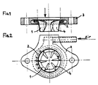
- la figure 1 représente une vue en coupe transversale d'une turbine conforme à la présente invention,
- la figure 2 représente une vue en plan de dessus de la même turbine,
- FIG. 1 represents a cross-sectional view of a turbine according to the present invention,
- FIG. 2 represents a plan view from above of the same turbine,
La bride à turbine d'homogénéisation représentée sur les figures 1 et 2 est notamment utilisée en combinaison avec le dispositif de correction décrit dans le brevet européen No 0026 198 pour améliorer l'efficacité de ce système de correction et elle comporte dans ce cas un circuit d'admission d'air additionnel représenté sur la Figure 2. Dans ce cas, l'air ou le gaz de correction de la carburation traverse la bride et les espaces inter-billes du roulement pour refroidir ce dernier et éventuellement le graisser :cas de l'admission d'air et de gaz de carter.The turbine flange homogenization shown in Figures 1 and 2 is used in particular in combination with the correction device described in European patent No. 0 026 198 to improve the effectiveness of this correction system and comprises in this case a additional air intake circuit shown in Figure 2. In this case, the air or the carburetor correction gas passes through the flange and the inter-ball spaces of the bearing to cool the latter and possibly grease it: case air and crankcase gas intake.
La bride représentée sur les figures 1 et 2 est destinée à être placée entre le carburateur et le collecteur d'admission du moteur. Cette bride est caractérisée par le fait que la turbine est centrée dans la bride grâce à un roulement à billes de préférence du type roulement butée, logé intégralement dans la bride. Par cette disposition, seule la turbine se trouve dans le flux du mélange carburé fourni par le carburateur.The flange shown in Figures 1 and 2 is intended to be placed between the carburetor and the engine intake manifold. This flange is characterized in that the turbine is centered in the flange by means of a ball bearing preferably of the thrust bearing type, housed entirely in the flange. By this arrangement, only the turbine is in the flow of the fuel mixture supplied by the carburetor.
La turbine et la partie mobile du roulement à billes présentent une certaine inertie en rotation suffisante pour amortir les fluctuations de vitesse de la veine gazeuse air-essence, afin de limiter le phénomène de double-succion de l'essence au niveau du carburateur et d'améliorer la répartition du mélange carburé dans les tubulures d'admission du moteur.The turbine and the movable part of the ball bearing have a certain inertia in rotation sufficient to dampen the speed fluctuations of the gas-air-gas stream, in order to limit the phenomenon of double-suction of the gasoline at the level of the carburetor and d '' improve the distribution of the fuel mixture in the engine intake manifolds.
Les figures 1 et 2 montrent que la turbine est constituée de plusieurs aillettes dont la profondeur (distance dans le sens de l'écoulement du bord d'attaque au bord de fuite) déborde au-delà de l'épaisseur du roulement à billes et de la bride. Ce débordement des ailettes au-delà de l'épaisseur du roulement et de la bride est une caractéristique particulière puisque la bride doit avoir une épaisseur réduite afin que sa mise en place sur moteur de véhicule moderne n'entraîne pas de modifications gênantes. Dans ces conditions, les ailettes doivent nécessairement déborder au-delà de l'épaisseur du roulement à billes et de la bride, comme indiqué par la figure 1, la profondeur des ailettes est importante notamment vers leur emplanture en raison du "pinceau" de vitesse étroit qu'engendre le papillon des gaz lorsqu'il est vers les positions de fermeture.Figures 1 and 2 show that the turbine is made up of several fins whose depth (distance in the direction of flow from the leading edge to the trailing edge) extends beyond the thickness of the ball bearing and the flange. This overflow of the fins beyond the thickness of the bearing and of the flange is a particular characteristic since the flange must have a reduced thickness so that its installation on a modern vehicle engine does not cause any annoying modifications. Under these conditions, the fins must necessarily overflow beyond the thickness of the ball bearing and the flange, as indicated in FIG. 1, the depth of the fins is important in particular towards their rooting because of the speed "brush" narrow that generates the throttle when it is towards the closed positions.
Les figures 1 et 2 montrent que les ailettes représentées convergent vers le centre du roulement à billes, mais sans l'atteindre, avec leur extrémité arrondie. L'incidence des ailettes est faible.Figures 1 and 2 show that the fins shown converge towards the center of the ball bearing, but without reaching it, with their rounded end. The incidence of fins is low.
Le roulement à billes est de préférence du type roulement de butée à une seule rangée de billes (Figure 1). Il présente la particularité d'être un roulement de butée à billes dans le sens de l'écoulement du mélange carburé et un palier à plateaux de glissement dans l'autre sens.The ball bearing is preferably of the thrust bearing type with a single row of balls (Figure 1). It has the particularity of being a thrust ball bearing in the direction of flow of the fuel mixture and a sliding plate bearing in the other direction.
Claims (4)
- Engine carbureted mixture homogenization device including a single stage axial turbine comprising a wheel (1) with several blades (4),centered inside a ball bearing (2) housed within a flange (3) placed after the carburetor such that the blades only are located in the flow of carbureted mixture driving the turbine, the blades converging towards the axis of rotation but do not reach it, their internal ends are free, distinguished in that the rotational inertia of the turbine and ball bearing assembly is sufficient to dampen speed fluctuations of the carbureted mixture, in order to improve the distribution of the carbureted mixture in engine inlet pipes and to limit gasoline double-suction phenomena in the carburetor, in that the blades (4) in the turbine (1) have a low setting incidence and are located around the internal periphery of a ring forming a nozzle which is linked to the internal ring of the ball bearing (2), in that the nozzle with the blades projects beyond the thickness of the bearing and the flange (3) in the direction of flow, and the blade leading edges are inclined in the direction of flow of the carbureted mixture from the root towards the center line of the bearing.
- Device according to claim 1, distinguished in that the depth of blades (4), the distance in the direction of flow from the blade leading edge to the trailing edge, reduces from the root towards the axis of rotation and the internal ends of the blade leading edges are rounded.
- Device according to claim 1 or 2 distinguished in that the peripheral ball bearing (2) forms a thrust ball bearing in the direction of flow of the carbureted mixture and a sliding plate bearing in the other direction, and for this purpose is fitted with a ring forming a ball bearing race on one side and a mobile sliding plate on the other side, the fixed sliding plate consisting of a hollow machined in flange (3) to form the fixed part of the ball bearing.
- Device according to one of claims 1, 2 or 3 distinguished in that the turbine and ball bearing assembly attachment flange (3) is fitted with an additional air or gas intake which passes through the spaces between the ball bearings to correct the proportion of the carbureted mixture and to cool the ball bearing and possibly to lubricate it (for sump air or gas intake).
Applications Claiming Priority (2)
| Application Number | Priority Date | Filing Date | Title |
|---|---|---|---|
| FR7909259 | 1979-04-12 | ||
| FR7909259A FR2453981A1 (en) | 1979-04-12 | 1979-04-12 | CARBURETOR CORRECTING DEVICE FOR MOTOR VEHICLE ENGINES FOR TRANSIENT OPERATING PHASES |
Related Parent Applications (1)
| Application Number | Title | Priority Date | Filing Date |
|---|---|---|---|
| EP80900679.4 Division | 1980-04-14 |
Publications (2)
| Publication Number | Publication Date |
|---|---|
| EP0105533A1 EP0105533A1 (en) | 1984-04-18 |
| EP0105533B1 true EP0105533B1 (en) | 1991-03-20 |
Family
ID=9224250
Family Applications (2)
| Application Number | Title | Priority Date | Filing Date |
|---|---|---|---|
| EP83200756A Expired - Lifetime EP0105533B1 (en) | 1979-04-12 | 1980-04-14 | Homogenization and supply improvement device for carburetor engines |
| EP80900679A Expired EP0026198B1 (en) | 1979-04-12 | 1980-10-23 | Correcting device for the carburation of engines of vehicules during transitional phases of operation |
Family Applications After (1)
| Application Number | Title | Priority Date | Filing Date |
|---|---|---|---|
| EP80900679A Expired EP0026198B1 (en) | 1979-04-12 | 1980-10-23 | Correcting device for the carburation of engines of vehicules during transitional phases of operation |
Country Status (4)
| Country | Link |
|---|---|
| EP (2) | EP0105533B1 (en) |
| DE (2) | DE3072192D1 (en) |
| FR (1) | FR2453981A1 (en) |
| WO (1) | WO1980002179A1 (en) |
Families Citing this family (3)
| Publication number | Priority date | Publication date | Assignee | Title |
|---|---|---|---|---|
| FR2453981A1 (en) * | 1979-04-12 | 1980-11-07 | Mandar Andre | CARBURETOR CORRECTING DEVICE FOR MOTOR VEHICLE ENGINES FOR TRANSIENT OPERATING PHASES |
| GB2142383A (en) * | 1983-06-30 | 1985-01-16 | Dei Lai Min | Carburettor with overrunning air supply to the idling system |
| GB2321084B (en) * | 1997-01-09 | 2000-05-10 | Brian Wilcockson | Charge mixing device for the intake of an i.c. engine |
Citations (1)
| Publication number | Priority date | Publication date | Assignee | Title |
|---|---|---|---|---|
| FR2453981A1 (en) * | 1979-04-12 | 1980-11-07 | Mandar Andre | CARBURETOR CORRECTING DEVICE FOR MOTOR VEHICLE ENGINES FOR TRANSIENT OPERATING PHASES |
Family Cites Families (20)
| Publication number | Priority date | Publication date | Assignee | Title |
|---|---|---|---|---|
| US1389909A (en) * | 1921-09-06 | Indicator | ||
| FR427114A (en) * | 1910-05-19 | 1911-07-27 | Marius Berliet | Speed limiter applicable to internal combustion engines |
| FR483481A (en) * | 1916-01-06 | 1917-07-11 | Automatic Carburetor Company | Device for automatically modifying the formation of fuel in internal combustion engines |
| GB182120A (en) * | 1921-06-23 | 1923-01-04 | Minot Olsen And Thurber Inc | Improvements in auxiliary air inlets for the intake manifolds of internal combustionengines |
| US1858835A (en) * | 1923-12-31 | 1932-05-17 | Bendix Stromberg Carbureter Co | Carburetor |
| US1823818A (en) * | 1926-03-19 | 1931-09-15 | Constantin Cesar Jean | Carburetor |
| GB305338A (en) * | 1927-12-23 | 1929-02-07 | Francis Henry Paton Beatson | Improvements in and relating to mixture supply systems of internal combustion engines |
| FR698512A (en) * | 1930-01-20 | 1931-01-31 | Advanced charge mixer for internal combustion engines | |
| FR746656A (en) * | 1932-12-01 | 1933-06-02 | Homogenization device for internal combustion engines | |
| GB519242A (en) * | 1937-10-11 | 1940-03-20 | Bosch Gmbh Robert | Improvements in or relating to auxiliary air admission devices for internal combustion engines |
| FR1478467A (en) * | 1966-02-28 | 1967-04-28 | Advanced training in control systems for enrichment circuits and economy circuits in carburettors or fuel systems | |
| FR1525059A (en) * | 1966-12-09 | 1968-05-17 | Nippon Denso Company | Control valve to prevent explosive combustion in the exhaust pipe of an internal combustion engine |
| US3470855A (en) * | 1967-06-26 | 1969-10-07 | Ernest A Von Seggern | Air valve actuating means and method for supplying auxiliary air to an internal combustion engine |
| ES362590A1 (en) * | 1969-01-16 | 1970-11-16 | Joan Claret | Improvements in the gasing media for explosion engines. (Machine-translation by Google Translate, not legally binding) |
| US3937202A (en) * | 1974-01-21 | 1976-02-10 | Mobil Oil Corporation | Economy driving aid |
| IT1023750B (en) * | 1974-09-19 | 1978-05-30 | Chicocini R | DEVICE FOR CONTROLLING THE DELIVERY OF LIQUID OR GASEOUS PROPELLENT FOR INTERNAL COMBUSTION ENGINES IN SPECIES INTENDED FOR SELF-TRACTION |
| CH620275A5 (en) * | 1976-05-07 | 1980-11-14 | Bosch Gmbh Robert | Device for more reliable switching of solenoid valves for overrun cut-off in carburettors |
| FR2376948A2 (en) * | 1977-01-05 | 1978-08-04 | Mayer Ferdy | Carburettor slow running jet control - has solenoid valve to close orifice when engine is braking vehicle |
| FR2385028A1 (en) * | 1977-03-25 | 1978-10-20 | Saint Martin Francois | Anti-return flow device for air duct - has free fan rotor mounted on shaft parallel to air flow |
| US4166382A (en) * | 1978-03-27 | 1979-09-04 | Petersen Paul S | Auto economy gauge |
-
1979
- 1979-04-12 FR FR7909259A patent/FR2453981A1/en active Granted
-
1980
- 1980-04-14 DE DE8383200756T patent/DE3072192D1/en not_active Expired - Lifetime
- 1980-04-14 WO PCT/FR1980/000058 patent/WO1980002179A1/en active IP Right Grant
- 1980-04-14 DE DE8080900679T patent/DE3071498D1/en not_active Expired
- 1980-04-14 EP EP83200756A patent/EP0105533B1/en not_active Expired - Lifetime
- 1980-10-23 EP EP80900679A patent/EP0026198B1/en not_active Expired
Patent Citations (1)
| Publication number | Priority date | Publication date | Assignee | Title |
|---|---|---|---|---|
| FR2453981A1 (en) * | 1979-04-12 | 1980-11-07 | Mandar Andre | CARBURETOR CORRECTING DEVICE FOR MOTOR VEHICLE ENGINES FOR TRANSIENT OPERATING PHASES |
Also Published As
| Publication number | Publication date |
|---|---|
| FR2453981A1 (en) | 1980-11-07 |
| DE3071498D1 (en) | 1986-04-24 |
| EP0026198A1 (en) | 1981-04-08 |
| EP0026198B1 (en) | 1986-03-19 |
| DE3072192D1 (en) | 1991-04-25 |
| WO1980002179A1 (en) | 1980-10-16 |
| EP0105533A1 (en) | 1984-04-18 |
| FR2453981B3 (en) | 1982-01-15 |
Similar Documents
| Publication | Publication Date | Title |
|---|---|---|
| CA2715209C (en) | Ventilation for a turbine wheel in a turbomachine | |
| FR2880391A1 (en) | DIFFUSER FOR AN ANNULAR COMBUSTION CHAMBER, IN PARTICULAR FOR AN AIRCRAFT TURBOMOTOR | |
| FR2814205A1 (en) | IMPROVED FLOW VEIN TURBOMACHINE | |
| EP0105533B1 (en) | Homogenization and supply improvement device for carburetor engines | |
| CA2721227A1 (en) | Dual-flow turbine engine for aircraft with low noise emission | |
| FR2497284A1 (en) | FUEL SUPPLY DEVICE FOR TWO-STROKE ENGINE | |
| FR3067387B1 (en) | AIR SUPPLY ECOPE FOR SUPPLYING A COOLING SYSTEM AND CONTROLLING THE GAMES OF A TURBINE | |
| FR2477634A1 (en) | CYLINDER HEAD FOR AIR-COOLED ENGINES | |
| FR2525692A1 (en) | FUEL INJECTOR FOR GAS TURBINE ENGINES | |
| FR2549897A1 (en) | INTAKE DEVICE FOR INTERNAL COMBUSTION ENGINE | |
| FR3125209A1 (en) | Rotating accessory for blowing hairdressing device | |
| EP0235031A1 (en) | Flame holder for the reheating system of a turbo jet | |
| FR2964151A1 (en) | Low pressure system for recirculation of exhaust gas for internal combustion engine i.e. diesel engine, of motor vehicle i.e. car, has injection device that is connected to inlet conduit of turbo compressor in tangential manner | |
| FR2486587A1 (en) | COMBUSTION IGNITION INTERNAL COMBUSTION ENGINE OF THE MUNI TYPE IN THE PISTON HEAD OF A PISTON BOWL OF THE SHAPE CORRESPONDING TO THAT OF A REVOLUTION BODY | |
| FR1464945A (en) | Internal combustion engine for lawn mower | |
| FR2495221A1 (en) | INTAKE DUCT STRUCTURE FOR INTERNAL COMBUSTION ENGINES | |
| BE418660A (en) | ||
| BE558982A (en) | ||
| FR2487009A1 (en) | INTERNAL COMBUSTION ENGINE HAVING A SECONDARY INTAKE CIRCUIT | |
| FR2507701A1 (en) | PROCESS FOR ATTENUATING SIFFLEMENT NOISE IN A TURBO GAS FLOW, ESPECIALLY COMPRESSOR SUCTION, AND CORRESPONDING SILENCING SYSTEM | |
| FR2654154A1 (en) | BUTTERFLY VALVE FOR FUEL SUPPLY DEVICE OF INTERNAL COMBUSTION ENGINE. | |
| JPS6126608Y2 (en) | ||
| FR3143667A1 (en) | Vortex mixer, intended to equip a heat engine exhaust line | |
| BE421598A (en) | ||
| FR2949813A1 (en) | EXHAUST LINE OF A MOTOR VEHICLE WITH A REAGENT INJECTOR |
Legal Events
| Date | Code | Title | Description |
|---|---|---|---|
| PUAI | Public reference made under article 153(3) epc to a published international application that has entered the european phase |
Free format text: ORIGINAL CODE: 0009012 |
|
| AC | Divisional application: reference to earlier application |
Ref document number: 26198 Country of ref document: EP |
|
| AK | Designated contracting states |
Designated state(s): CH DE FR GB LI NL SE |
|
| 17P | Request for examination filed |
Effective date: 19840410 |
|
| RAP1 | Party data changed (applicant data changed or rights of an application transferred) |
Owner name: MANDAR, MARTINE Owner name: MANDAR, ANDRE |
|
| GRAA | (expected) grant |
Free format text: ORIGINAL CODE: 0009210 |
|
| AC | Divisional application: reference to earlier application |
Ref document number: 26198 Country of ref document: EP |
|
| AK | Designated contracting states |
Kind code of ref document: B1 Designated state(s): CH DE FR GB LI NL SE |
|
| REF | Corresponds to: |
Ref document number: 3072192 Country of ref document: DE Date of ref document: 19910425 |
|
| NLV1 | Nl: lapsed or annulled due to failure to fulfill the requirements of art. 29p and 29m of the patents act | ||
| GBT | Gb: translation of ep patent filed (gb section 77(6)(a)/1977) | ||
| NLXE | Nl: other communications concerning ep-patents (part 3 heading xe) |
Free format text: REQUEST FOR RESTORATION TO THE PRIOR STATE HAS BEEN FILED ON 910823 |
|
| PLBE | No opposition filed within time limit |
Free format text: ORIGINAL CODE: 0009261 |
|
| STAA | Information on the status of an ep patent application or granted ep patent |
Free format text: STATUS: NO OPPOSITION FILED WITHIN TIME LIMIT |
|
| 26N | No opposition filed | ||
| PGFP | Annual fee paid to national office [announced via postgrant information from national office to epo] |
Ref country code: GB Payment date: 19920327 Year of fee payment: 13 |
|
| NLXE | Nl: other communications concerning ep-patents (part 3 heading xe) |
Free format text: REQUEST FOR RESTORATION TO THE PRIOR STATE AS PROVIDED FOR IN ART. 17A OF THE PATENTS ACT HAS BEEN GRANTED;THE RESTORATION OF THE PATENT HAS BEEN ENTERED IN THE PATENT REGISTER |
|
| PG25 | Lapsed in a contracting state [announced via postgrant information from national office to epo] |
Ref country code: GB Effective date: 19930414 |
|
| GBPC | Gb: european patent ceased through non-payment of renewal fee |
Effective date: 19930414 |
|
| EAL | Se: european patent in force in sweden |
Ref document number: 83200756.1 |
|
| PGFP | Annual fee paid to national office [announced via postgrant information from national office to epo] |
Ref country code: NL Payment date: 19950430 Year of fee payment: 16 |
|
| PGFP | Annual fee paid to national office [announced via postgrant information from national office to epo] |
Ref country code: FR Payment date: 19950523 Year of fee payment: 16 |
|
| PGFP | Annual fee paid to national office [announced via postgrant information from national office to epo] |
Ref country code: SE Payment date: 19950524 Year of fee payment: 16 |
|
| PGFP | Annual fee paid to national office [announced via postgrant information from national office to epo] |
Ref country code: DE Payment date: 19950612 Year of fee payment: 16 |
|
| PGFP | Annual fee paid to national office [announced via postgrant information from national office to epo] |
Ref country code: CH Payment date: 19950728 Year of fee payment: 16 |
|
| PG25 | Lapsed in a contracting state [announced via postgrant information from national office to epo] |
Ref country code: SE Free format text: THE PATENT HAS BEEN ANNULLED BY A DECISION OF A NATIONAL AUTHORITY Effective date: 19960415 |
|
| PG25 | Lapsed in a contracting state [announced via postgrant information from national office to epo] |
Ref country code: LI Effective date: 19960430 Ref country code: CH Effective date: 19960430 |
|
| PG25 | Lapsed in a contracting state [announced via postgrant information from national office to epo] |
Ref country code: NL Effective date: 19961101 |
|
| REG | Reference to a national code |
Ref country code: CH Ref legal event code: PL |
|
| PG25 | Lapsed in a contracting state [announced via postgrant information from national office to epo] |
Ref country code: FR Effective date: 19961227 |
|
| PG25 | Lapsed in a contracting state [announced via postgrant information from national office to epo] |
Ref country code: DE Effective date: 19970101 |
|
| NLV4 | Nl: lapsed or anulled due to non-payment of the annual fee |
Effective date: 19961101 |
|
| EUG | Se: european patent has lapsed |
Ref document number: 83200756.1 |
|
| REG | Reference to a national code |
Ref country code: FR Ref legal event code: ST |
|
| APAH | Appeal reference modified |
Free format text: ORIGINAL CODE: EPIDOSCREFNO |