EP0105496B1 - Verfahren und Vorrichtung zur genauen Zuführung von Fluidmischungen - Google Patents
Verfahren und Vorrichtung zur genauen Zuführung von Fluidmischungen Download PDFInfo
- Publication number
- EP0105496B1 EP0105496B1 EP83109810A EP83109810A EP0105496B1 EP 0105496 B1 EP0105496 B1 EP 0105496B1 EP 83109810 A EP83109810 A EP 83109810A EP 83109810 A EP83109810 A EP 83109810A EP 0105496 B1 EP0105496 B1 EP 0105496B1
- Authority
- EP
- European Patent Office
- Prior art keywords
- pump
- rate
- valve
- fluid
- period
- Prior art date
- Legal status (The legal status is an assumption and is not a legal conclusion. Google has not performed a legal analysis and makes no representation as to the accuracy of the status listed.)
- Expired
Links
Images


Classifications
-
- G—PHYSICS
- G01—MEASURING; TESTING
- G01N—INVESTIGATING OR ANALYSING MATERIALS BY DETERMINING THEIR CHEMICAL OR PHYSICAL PROPERTIES
- G01N30/00—Investigating or analysing materials by separation into components using adsorption, absorption or similar phenomena or using ion-exchange, e.g. chromatography or field flow fractionation
- G01N30/02—Column chromatography
- G01N30/26—Conditioning of the fluid carrier; Flow patterns
- G01N30/28—Control of physical parameters of the fluid carrier
- G01N30/34—Control of physical parameters of the fluid carrier of fluid composition, e.g. gradient
-
- B—PERFORMING OPERATIONS; TRANSPORTING
- B01—PHYSICAL OR CHEMICAL PROCESSES OR APPARATUS IN GENERAL
- B01F—MIXING, e.g. DISSOLVING, EMULSIFYING OR DISPERSING
- B01F35/00—Accessories for mixers; Auxiliary operations or auxiliary devices; Parts or details of general application
- B01F35/80—Forming a predetermined ratio of the substances to be mixed
- B01F35/83—Forming a predetermined ratio of the substances to be mixed by controlling the ratio of two or more flows, e.g. using flow sensing or flow controlling devices
- B01F35/833—Flow control by valves, e.g. opening intermittently
-
- G—PHYSICS
- G05—CONTROLLING; REGULATING
- G05D—SYSTEMS FOR CONTROLLING OR REGULATING NON-ELECTRIC VARIABLES
- G05D11/00—Control of flow ratio
- G05D11/02—Controlling ratio of two or more flows of fluid or fluent material
- G05D11/13—Controlling ratio of two or more flows of fluid or fluent material characterised by the use of electric means
- G05D11/131—Controlling ratio of two or more flows of fluid or fluent material characterised by the use of electric means by measuring the values related to the quantity of the individual components
- G05D11/132—Controlling ratio of two or more flows of fluid or fluent material characterised by the use of electric means by measuring the values related to the quantity of the individual components by controlling the flow of the individual components
-
- Y—GENERAL TAGGING OF NEW TECHNOLOGICAL DEVELOPMENTS; GENERAL TAGGING OF CROSS-SECTIONAL TECHNOLOGIES SPANNING OVER SEVERAL SECTIONS OF THE IPC; TECHNICAL SUBJECTS COVERED BY FORMER USPC CROSS-REFERENCE ART COLLECTIONS [XRACs] AND DIGESTS
- Y10—TECHNICAL SUBJECTS COVERED BY FORMER USPC
- Y10T—TECHNICAL SUBJECTS COVERED BY FORMER US CLASSIFICATION
- Y10T137/00—Fluid handling
- Y10T137/8593—Systems
- Y10T137/86389—Programmer or timer
- Y10T137/86445—Plural, sequential, valve actuations
Definitions
- This invention relates to a method and system of improving the fluid blending performance of a pumping system.
- Fluid blending or proportioning is accomplished by means of plural valves (usually solenoid operated) positioned between each reservoir and the mixer.
- the valves operate during a valve cycle, typically between 5 and 7 seconds.
- Each valve is open a certain fraction of the valve cycle time T". In the case of four valves, A, B, C, D, while the valve for liquid A is open, the valves for the liquids B, C, and D are closed and so on.
- the fraction of time each valve is open each valve cycle determines the average concentration of that liquid exiting the mixer.
- the pump typically consist of two or more positive displacement pump heads, each operating out of phase to maintain a smooth flow profile. If three pump heads are used, each head's piston is 120° out of phase with the two other pistons. For each pump head, the piston displacement is a sinusoidal function of time.
- the pump period is determined by the pump delivery volume per cycle divided by the volumetric throughput rate.
- the inlet and outlet of the pump heads are joined at manifolds, which divide the flow at the pump inlet and combine the flow at the pump outlet.
- the flow into each pump head is pulsatile, i.e., when liquid is drawn into a pump head cavity by retraction of the piston, there is no flow out of the given cavity, and when liquid is forced out of the cavity by the advancing piston there is no flow into it.
- US-A-4,128,476 discloses a method and system for controlling the composition of a liquid chromatographic carrier wherein the output pressure of the positive displacement pump is sensed to measure onset of output flow as a time lag from the beginning of the output stroke to give an estimate of the input filling time lag from the beginning of the fill stroke. This estimate is used to recompute a proportional module output for controlling the timing of a porportioning valve at the inlet of the displacement pump so as to bring the actual operating conditions of the pump fill cycle into correspondence with the predetermined demanded ratios of the components.
- This prior art method and system require a complicated computer system and a periphery because the carrier flow has to be sensed in order to measure the various time periods which are to be processed. This prior art method is complicated further by the necessity to repeat the computation at appropriate intervals during a run to recalibrate the system.
- the computer means stores constants defining plural straight line segments representing the non-interacting relationship between the pump frequency and valve cycle frequency, and calculates the valve period for a selected pump frequency by adding the base point of a valve period segment to the product of the slope of that segmental relationship times the difference beween the base point of pump frequency for that valve period segment and the selected pump frequency in order to ascertain the desired valve period.
- the exact values of the constants are arbitrary, but they must not produce line segments containing points which can be described by the laterative relation where fp is the pump frequency or inverse of the pump period, Tpr I is the number of pump heads in the pump, n and m are low valued integers, Ty is the valve period, and k is a conversion factor.
- the ratio of the pump period to the valve period can be selected so that the fluid flow harmonics coincide with the missing harmonics in the flowrate of the fluid flowing from the reservoir.
- FIG. 1 In this system, there is shown a number of reservoirs 10, each holding a different mixable liquid or fluid A, B, C, D. These liquids are to be blended or mixed together in prescribed proportions. To this end, these fluids are each directed to a mixing chamber 12 through conduits 16 and respective solenoid valves 14 denoted A, B, C, D, corresponding to each of the fluid reservoirs 10. Before passing to the mixing chamber, each fluid A, B, C, D is passed through a filter (not shown) which removes solid particulates. Each of the solenoid valves 14 uses a fast acting solenoid which either permits or bars flow along its respective conduit 16.
- a blend is forged by periodically opening each valve 14 for a period of time during the total valve period proportional to the fraction of that liquid desired. For example, if a 75% blend of fluid A and 25% blend of fluid B were desired, the A valve 14 would be open for 4.5 seconds and then the B valve 14 open for 1.5 seconds for a total valve period ofTy of 6 seconds. This cycle is repeated each valve period T". Only one valve is open at a given time. Typically a 5-7 second valve cycle T v is used in liquid chromatography although other periods can be used as desired.
- the blended fluid is passed to a pump 18 which includes an inlet manifold 20, an outlet manifold 22 and three pump heads 24, 26 and 28.
- a pump with one, two or any other number of heads may be used as desired.
- a three-headed pump is preferred since it provides a more constant level output flow rate.
- This pump preferably is a positive displacement pump and operated with the heads 120 0 out of phase. Since this pump is conventional and available commercially it need not be described further.
- the piston displacement is a sinusoidal function of time. The pump period is determined by the pump delivery volume for one cycle of each pump head divided by the volumetric throughput rate of the system.
- Inlet and exit check valves on each pump head ensure that each head delivers fluid at the proper times in the pump cycle.
- the inlet and outlet of the pump heads 24, 26 and 28 are joined by the manifolds 20 and 22 which divide the flow at the pump inlet and combine the flow at the outlet.
- the check valves Because of the check valves, the flow into the fluid cavity of each pump head 24, 26 and 28 is pulsatile, i.e., when liquid is drawn into the cavity by retraction of the piston there is no flow out of the given cavity, and when the liquid is forced out of the cavity by the advancing piston, there is no flow into it.
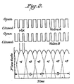
- the precise characteristics of the flow pulsations depend upon the driving mechanism of the pistons, on the fluid compressibility, and on the check valve response time. Therefore, the three pistons produce six flow pulsations into and out of the pump for each pump cycle an example of which may be seen in the pump flow illustration of Figure 2.
- the controller 32 includes a pump drive control 34 which actuates a pump drive 40, and which in turn drives through the linkages 42 the respective pump heads 24, 26 and 28.
- the pump drive control 34 operates in response to the desired flow rate information 36 which in turn is set typically by the operator of the system on the control panel 30.
- the operator also sets the blend composition information 37 which is transferred to a solvent ratio controller 38 by the control panel 30.
- the open and closed time of each vlave is determined by the controller 38 and implemented by energizing the several solenoids 14 at their proper times through control lines 44.
- the system described is conventional and may, for example, be that sold by E. I. du Pont de Nemours and Company, Wilmington, DE as their Model 850 HPLC system.
- the problem resulting from the periodicity of the pump flow interacting with the periodicity of the solenoid valves to produce slow unexpected variations in the fluid blends is solved.
- the solution includes modification of the valve period T v based upon motor rate information obtained by the solvent ratio control 38 from the pump drive control 34.
- An example of this undesirable interaction may be seen in Figure 2 where the valves A and B are illustrated as being cycled open and closed over the period T v during the pump flow period Tp. Under these conditions, the valves provide a 67% A 33% B blend.
- the pulsations of the pump and valves are illustrated as being in perfect synchronization such that maximum flow rate occurs when the valve A is open.
- the minimum flow occurs when the valve B is open since the pump flow was at a minimum during the opening of the valve B.
- the blend contains more of component A than expected from the valve period.
- the exact synchronization between the pump period and valve period seldom occurs. Rather there is a slow fluctuation in concentration as the valves and flow pulsations move in and out of phase.
- errors in such blending are reduced or eliminated by selecting valve periods which do not cause interaction beween the respective valve periods and flow periods.
- Preferably errors are avoided by setting the valve period to be a function of the flow rate. More specifically the cyclic rate, of the pump is adjusted to provide a desired flow rate and then the time proportioning cyclic rate of the valves is adjusted to be non-harmonic with the pump cyclic rate and the larger pump rate harmonics. In this manner the makeup of the components and the fluid stream is accurately and consistently maintained.
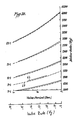
- FIGS 3A and 3B a graphical representation of the resonance relationships between the valve rate l fT v and the pump or motor rate and for selected major harmonics between the valve rate and the motor rate. These relationships are those at which the undesired interactions occur between the pump rate and valve period for a particular pump.
- the dashed lines 60 bearing the designations 1/ 2, 2/3, 3/4, 1/1, etc. represent the regions at which the valve period and the motor rate will interact to cause slowly varying concentrations.
- valve periods are selected which do not lie near these interaction or resonance lines. More specifically, blend concentration errors are avoided by delinerately setting the valve period as specified functions of the flow rate, i.e., the motor rate.
- These specified functions or nonresonant regions are denoted by straight line segments 62 (solid lines) drawn in the graph of Figures 3A and 3B.
- the straight line segments denote safe operating regions for the valve period as a function of motor rate for every motor rate that would typically be used in a particular pumping system. It is noted that as motor rates increase, different harmonics of the valve rates and motor rate interact. It will be appreciated, of course, that the relationship illustrated in Figures 3A and 3B are for a specific pump, in this case the pump used in the Du Pont Model 850 HPLC unit. Formulas for determining these relationships are discussed below.
- Each line segment 62 representing a safe non-harmonic operating region, is defined by the formula where VPS(I), MS(I), MRS(I) are constants described in Table 1 below, depending on the motor rate segment and f m is the desired motor rate. These motor rate segments ranging from 80 Hz to 4050 Hz are shown tabulated in the following table.
- the base or starting point of these straight line segments is selected so that each line is mutually exclusive and does not overlap any other line.
- the solvent ratio control 38 stores this table and solves the formula using the stored constrants for each selected pump rate (motor rate-MRS.) and controls the valve switching accordingly.
- the solvent ratio control 38 ( Figure 1) has a microprocessor which computes following the flow chart depicted in Figure 4 in which the flow rate and desired fluid composition are inputs from the operator at the control panel 30.
- the pump drive control 34 calculates the motor rate needed to achieve such flow and controls the pump drive 40 accordingly for operating the pump heads 24, 26 and 28 at the desired rate.
- the valve rate needed for nonharmonic or noninteractive operation in accordance with this invention is computed by the solvent ratio control 38. This is accomplished by looking up the necessary constants of stored Table 1 for the motor rate f m corresponding to that desired flow rate to calculate the valve period T v and from that the open time for each valve.
- the output valve data is then used during the operating cycle to control the valves 14 to provide the desired blend. At this point the program stops until a new input flow rate and desired blend is inputed into the controller 32 by the operator.
- the system of this invention utilizing the controller 32 operates in essentially the same manner as the method just described utilizing the controller with its microprocessor (not shown) which functions with the flow rate and desired blend as inputs to control the pump drive 34 and the solvent ratio control 38.
- controller 32 instead of using a table lookup, may actually compute the valve period from the basic formula.
- This basic formula may be derived from the followiing analysis.
- the volumetric flow rate profile Q(t) has a period Tp/3, where Tp is the period of each pump and Q(t) can be represented by where Q is the average flow rate through the system, the constants e m are the positive Fourier components of the flow rate and a m are phase constants.
- n*I*a is not an integer.
- a is the mean concentration of the liquid in question in the pump effluent.
- the integers n and m are identified by having no common integer factors other than unity and where Tp and T v are the pump and valve cycle periods respectively. The two positive integers n and m thus determine the slow concentration modulation interactions between the pump flow cycle (period T p /3) and the input concentration valve cycle with period T v .
Claims (11)
daß der Zyklus der Steuerung der Zweitanteile so eingestellt wird, daß er in einer nichtharmonischen Beziehung zu dem Zyklus der Pumpe teht, wodurch die Mischung der Bestandteile des Fluidstroms genau aufrechterhelten wird.

eine Computereinrichtung in der Steuerung (32), die auf das Pumpenantriebssignal anspricht und den Zyklus des Ventilsignals so festsetzt, daß er in nichtharmonischer Beziehung mit dem Pumpenzyklus steht, wodurch die Fluidmischung auf ihrem gewünschten Wert gehalten wird.

Priority Applications (1)
| Application Number | Priority Date | Filing Date | Title |
|---|---|---|---|
| AT83109810T ATE45815T1 (de) | 1982-09-30 | 1983-09-30 | Verfahren und vorrichtung zur genauen zufuehrung von fluidmischungen. |
Applications Claiming Priority (2)
| Application Number | Priority Date | Filing Date | Title |
|---|---|---|---|
| US430837 | 1982-09-30 | ||
| US06/430,837 US4427298A (en) | 1982-09-30 | 1982-09-30 | Method and system for accurately providing fluid blends |
Publications (3)
| Publication Number | Publication Date |
|---|---|
| EP0105496A2 EP0105496A2 (de) | 1984-04-18 |
| EP0105496A3 EP0105496A3 (en) | 1985-07-10 |
| EP0105496B1 true EP0105496B1 (de) | 1989-08-23 |
Family
ID=23709268
Family Applications (1)
| Application Number | Title | Priority Date | Filing Date |
|---|---|---|---|
| EP83109810A Expired EP0105496B1 (de) | 1982-09-30 | 1983-09-30 | Verfahren und Vorrichtung zur genauen Zuführung von Fluidmischungen |
Country Status (6)
| Country | Link |
|---|---|
| US (1) | US4427298A (de) |
| EP (1) | EP0105496B1 (de) |
| AT (1) | ATE45815T1 (de) |
| AU (1) | AU562105B2 (de) |
| CA (1) | CA1200699A (de) |
| DE (1) | DE3380451D1 (de) |
Families Citing this family (34)
| Publication number | Priority date | Publication date | Assignee | Title |
|---|---|---|---|---|
| US4614438A (en) * | 1984-04-24 | 1986-09-30 | Kabushiki Kaisha Kokusai Technicals | Method of mixing fuel oils |
| US4595496A (en) * | 1984-06-29 | 1986-06-17 | Millipore Corporation | Liquid composition control |
| DE3431112A1 (de) * | 1984-08-24 | 1986-03-06 | Spühl AG, St. Gallen | Mischkopf zur reaktiven mischung von kunststoff-komponenten |
| DE3442227A1 (de) * | 1984-11-19 | 1986-05-28 | Kernforschungsanlage Jülich GmbH, 5170 Jülich | Verfahren und vorrichtung zur ionenchromatographischen bestimmung des spurengehalts von waessrigen proben |
| US4794806A (en) * | 1987-02-13 | 1989-01-03 | Nicoli David F | Automatic dilution system |
| US4919595A (en) * | 1987-03-03 | 1990-04-24 | Beckman Instruments, Inc. | Fluid delivery system with deficit flow compensation |
| JPS63278539A (ja) * | 1987-05-11 | 1988-11-16 | Tosoh Corp | 液分注装置 |
| US4767279A (en) * | 1987-06-02 | 1988-08-30 | Millipore Corporation | Fluid composition and volumetric delivery control |
| CA1290744C (en) * | 1987-07-08 | 1991-10-15 | Laurent Verreault | Process and an apparatus for mixing substances |
| US5135658A (en) * | 1990-05-04 | 1992-08-04 | Bio-Rad Laboratories, Inc. | Method for reducing detector noise in a chromatography system |
| US5089124A (en) * | 1990-07-18 | 1992-02-18 | Biotage Inc. | Gradient generation control for large scale liquid chromatography |
| US5823669A (en) * | 1991-05-03 | 1998-10-20 | Lolco Packaging Corp. | Method for blending diverse blowing agents |
| US5423607A (en) * | 1991-05-03 | 1995-06-13 | Dolco Packaging Corp. | Method for blending diverse blowing agents |
| CA2210334C (en) * | 1995-02-24 | 2005-04-26 | Exxon Chemical Patents, Inc. | Additive blending system and method |
| US6056431A (en) * | 1997-09-05 | 2000-05-02 | Eastman Kodak Company | Modified passive liquefier batch transition process |
| SG148839A1 (en) * | 2000-07-31 | 2009-01-29 | Celerity Inc | Method and apparatus for blending process materials |
| DE10048513A1 (de) * | 2000-09-29 | 2002-04-11 | Degussa | Verfahren zur kontinuierlichen Herstellung von Stoff- und Reaktionsgemischen und Vorrichtung zu seiner Durchführung |
| US6568559B2 (en) * | 2000-11-24 | 2003-05-27 | Wanner Engineering, Inc. | Termite control system with multi-fluid proportion metering and batch signal metering |
| US20050098578A1 (en) * | 2002-09-13 | 2005-05-12 | Ford Motor Company | System for dispensing reactant mixtures |
| CA2466799C (en) * | 2004-05-07 | 2011-10-18 | Oden Corporation | An improved continuous liquid stream blender |
| US20070185619A1 (en) * | 2004-09-02 | 2007-08-09 | Fermier Adam M | Automated solution generator |
| US20060093515A1 (en) * | 2004-11-03 | 2006-05-04 | Fermier Adam M | Automated solution generator |
| WO2008143828A1 (en) * | 2007-05-14 | 2008-11-27 | Clyde Meriwether Smith | Systems and methods for supplying and/or dispensing fluid |
| US20090068034A1 (en) * | 2007-09-12 | 2009-03-12 | Pumptec, Inc. | Pumping system with precise ratio output |
| US9645123B2 (en) | 2010-01-11 | 2017-05-09 | Waters Technologies Corporation | Manifold for solvent mixing in liquid chromatography systems |
| US9791107B2 (en) * | 2011-07-27 | 2017-10-17 | Agilent Technologies, Inc. | Packet-wise proportioning followed by immediate longitudinal mixing |
| US9316216B1 (en) * | 2012-03-28 | 2016-04-19 | Pumptec, Inc. | Proportioning pump, control systems and applicator apparatus |
| US20130294969A1 (en) * | 2012-05-02 | 2013-11-07 | Nellcor Puritan Bennett Llc | Wireless, Reusable, Rechargeable Medical Sensors and System for Recharging and Disinfecting the Same |
| DE102012010544B4 (de) * | 2012-05-29 | 2017-02-09 | J. Wagner Ag | Verfahren und Vorrichtung zum Mischen wenigstens zweier flüssiger Komponenten |
| ITMI20130660A1 (it) * | 2013-04-22 | 2014-10-23 | Emanuela Paci | Stazione di stoccaggio, prelievo e ricircolo di una sostanza fluida |
| US20170223921A1 (en) * | 2016-02-08 | 2017-08-10 | Delaware Capital Formation, Inc. | On-site chemical blending and dispensing system |
| US10760557B1 (en) | 2016-05-06 | 2020-09-01 | Pumptec, Inc. | High efficiency, high pressure pump suitable for remote installations and solar power sources |
| US10823160B1 (en) | 2017-01-12 | 2020-11-03 | Pumptec Inc. | Compact pump with reduced vibration and reduced thermal degradation |
| EP4065972A1 (de) | 2019-11-27 | 2022-10-05 | Waters Technologies Corporation | Passiv dämpfendes gradienten-dosierventil |
Family Cites Families (13)
| Publication number | Priority date | Publication date | Assignee | Title |
|---|---|---|---|---|
| US3398689A (en) | 1966-01-05 | 1968-08-27 | Instrumentation Specialties Co | Apparatus providing a constant-rate two-component flow stream |
| US3446057A (en) | 1966-10-14 | 1969-05-27 | Varian Associates | Method and apparatus for chromatography |
| US3608869A (en) | 1969-05-28 | 1971-09-28 | Texaco Inc | System for blending liquid ingredients |
| US3869067A (en) | 1972-06-26 | 1975-03-04 | Du Pont | Apparatus for gradient elution |
| US4018685A (en) | 1975-10-24 | 1977-04-19 | Union Oil Company Of California | Automatic liquid mixing device |
| JPS52133294A (en) * | 1976-05-01 | 1977-11-08 | Nippon Bunko Kogyo Kk | Pumping system and liquid transfer process for liquid chromatography |
| US4004884A (en) | 1976-07-02 | 1977-01-25 | Hoffmann-La Roche Inc. | Time division metering system |
| US4128476A (en) | 1977-06-14 | 1978-12-05 | Spectra-Physics, Inc. | Carrier composition control for liquid chromatographic systems |
| US4162689A (en) | 1977-07-14 | 1979-07-31 | Hoffmann-La Roche Inc. | Time division flow control |
| DE2808183A1 (de) | 1978-02-25 | 1979-09-06 | Hedrich Vakuumanlagen Wilhelm | Vorrichtungen fuer giessharzanlagen zum kontrollieren gleicher und/oder unterschiedlicher, auch synchronisierter ausstossmengen fliessfaehiger bis hochviskoser medien |
| DE2905160C2 (de) | 1979-02-10 | 1981-01-08 | Hewlett-Packard Gmbh, 7030 Boeblingen | Vorrichtung für die Erzeugung von Elutionsmittelgradienten in der Flüssigkeitschromatographie |
| JPS55122149A (en) | 1979-03-14 | 1980-09-19 | Japan Spectroscopic Co | Method and apparatus for supplying solvent in liquid chromatograph |
| US4341327A (en) | 1980-02-28 | 1982-07-27 | Vernon Zeitz | Digital proportional metering pumping system |
-
1982
- 1982-09-30 US US06/430,837 patent/US4427298A/en not_active Expired - Fee Related
-
1983
- 1983-09-29 AU AU19727/83A patent/AU562105B2/en not_active Ceased
- 1983-09-29 CA CA000438039A patent/CA1200699A/en not_active Expired
- 1983-09-30 EP EP83109810A patent/EP0105496B1/de not_active Expired
- 1983-09-30 AT AT83109810T patent/ATE45815T1/de not_active IP Right Cessation
- 1983-09-30 DE DE8383109810T patent/DE3380451D1/de not_active Expired
Also Published As
| Publication number | Publication date |
|---|---|
| DE3380451D1 (en) | 1989-09-28 |
| AU1972783A (en) | 1984-04-05 |
| EP0105496A2 (de) | 1984-04-18 |
| ATE45815T1 (de) | 1989-09-15 |
| CA1200699A (en) | 1986-02-18 |
| EP0105496A3 (en) | 1985-07-10 |
| US4427298A (en) | 1984-01-24 |
| AU562105B2 (en) | 1987-05-28 |
Similar Documents
| Publication | Publication Date | Title |
|---|---|---|
| EP0105496B1 (de) | Verfahren und Vorrichtung zur genauen Zuführung von Fluidmischungen | |
| US4595496A (en) | Liquid composition control | |
| US5360320A (en) | Multiple solvent delivery system | |
| EP0327609B1 (de) | Gemisch- und volumensteuerung zur flüssigkeitslieferung | |
| US4128476A (en) | Carrier composition control for liquid chromatographic systems | |
| US4137011A (en) | Flow control system for liquid chromatographs | |
| EP0260764B1 (de) | Flüssigkeitschromatograph | |
| EP0494453B1 (de) | Verfahren und Vorrichtung zur Messung des Materialflusses in einer Zweikomponenten-Abgabevorrichtung | |
| US5089124A (en) | Gradient generation control for large scale liquid chromatography | |
| EP0583003A1 (de) | Eine Flüssigkeit abmessendes, mischendes und deren Zusammensetzung überwachendes System | |
| US3934456A (en) | Solvent gradient generator for chromatography systems | |
| US20130308415A1 (en) | Valve switch modulation for reducing errors due to oscillations of the inlet fluid of a pump system | |
| CA2025450A1 (en) | Variable blending dispenser | |
| US4728434A (en) | Liquid chromatography | |
| US4964985A (en) | Liquid chromatograph | |
| US4954253A (en) | Device for preparing a gradient solution for a high-pressure liquid chromatograph | |
| US4821761A (en) | Closed loop pump control system | |
| FI88343B (fi) | Foerfarande och anordning foer beaktande av varierande volym och floede vid reglering av genomstroemningsprocesser | |
| US3107034A (en) | Liquid supply and mixing system | |
| US4618935A (en) | Liquid chromatography controller | |
| CN111812262B (zh) | 一种液相色谱多元低压低比例控制方法及装置 | |
| JP3411596B2 (ja) | 高粘度液充填装置 | |
| SU1282823A3 (ru) | Способ регулировани соотношени компонентов смеси | |
| US5291418A (en) | Adjustment of electric potential by automatic titration | |
| DE3021152A1 (de) | Vorrichtung zum messen einer stroemenden fluidmenge |
Legal Events
| Date | Code | Title | Description |
|---|---|---|---|
| PUAI | Public reference made under article 153(3) epc to a published international application that has entered the european phase |
Free format text: ORIGINAL CODE: 0009012 |
|
| AK | Designated contracting states |
Designated state(s): AT BE CH DE FR GB IT LI LU NL SE |
|
| PUAL | Search report despatched |
Free format text: ORIGINAL CODE: 0009013 |
|
| AK | Designated contracting states |
Designated state(s): AT BE CH DE FR GB IT LI LU NL SE |
|
| 17P | Request for examination filed |
Effective date: 19851217 |
|
| 17Q | First examination report despatched |
Effective date: 19870513 |
|
| RAP1 | Party data changed (applicant data changed or rights of an application transferred) |
Owner name: THE ANSPEC COMPANY, INC. |
|
| GRAA | (expected) grant |
Free format text: ORIGINAL CODE: 0009210 |
|
| AK | Designated contracting states |
Kind code of ref document: B1 Designated state(s): AT BE CH DE FR GB IT LI LU NL SE |
|
| REF | Corresponds to: |
Ref document number: 45815 Country of ref document: AT Date of ref document: 19890915 Kind code of ref document: T |
|
| PGFP | Annual fee paid to national office [announced via postgrant information from national office to epo] |
Ref country code: SE Payment date: 19890828 Year of fee payment: 7 |
|
| PGFP | Annual fee paid to national office [announced via postgrant information from national office to epo] |
Ref country code: LU Payment date: 19890927 Year of fee payment: 7 Ref country code: FR Payment date: 19890927 Year of fee payment: 7 |
|
| PGFP | Annual fee paid to national office [announced via postgrant information from national office to epo] |
Ref country code: DE Payment date: 19890928 Year of fee payment: 7 |
|
| REF | Corresponds to: |
Ref document number: 3380451 Country of ref document: DE Date of ref document: 19890928 |
|
| ET | Fr: translation filed | ||
| ITTA | It: last paid annual fee | ||
| PG25 | Lapsed in a contracting state [announced via postgrant information from national office to epo] |
Ref country code: LU Free format text: LAPSE BECAUSE OF NON-PAYMENT OF DUE FEES Effective date: 19890930 |
|
| PGFP | Annual fee paid to national office [announced via postgrant information from national office to epo] |
Ref country code: NL Payment date: 19890930 Year of fee payment: 7 Ref country code: GB Payment date: 19890930 Year of fee payment: 7 Ref country code: AT Payment date: 19890930 Year of fee payment: 7 |
|
| PGFP | Annual fee paid to national office [announced via postgrant information from national office to epo] |
Ref country code: CH Payment date: 19891004 Year of fee payment: 7 |
|
| PGFP | Annual fee paid to national office [announced via postgrant information from national office to epo] |
Ref country code: BE Payment date: 19891018 Year of fee payment: 7 |
|
| ITF | It: translation for a ep patent filed |
Owner name: MARCHI & MITTLER S.R.L. |
|
| PLBE | No opposition filed within time limit |
Free format text: ORIGINAL CODE: 0009261 |
|
| STAA | Information on the status of an ep patent application or granted ep patent |
Free format text: STATUS: NO OPPOSITION FILED WITHIN TIME LIMIT |
|
| 26N | No opposition filed | ||
| PG25 | Lapsed in a contracting state [announced via postgrant information from national office to epo] |
Ref country code: LI Effective date: 19900930 Ref country code: GB Effective date: 19900930 Ref country code: CH Effective date: 19900930 Ref country code: BE Effective date: 19900930 Ref country code: AT Effective date: 19900930 |
|
| PG25 | Lapsed in a contracting state [announced via postgrant information from national office to epo] |
Ref country code: SE Effective date: 19901001 |
|
| BERE | Be: lapsed |
Owner name: THE ANSPEC CY INC. Effective date: 19900930 |
|
| PG25 | Lapsed in a contracting state [announced via postgrant information from national office to epo] |
Ref country code: NL Effective date: 19910401 |
|
| NLV4 | Nl: lapsed or anulled due to non-payment of the annual fee | ||
| GBPC | Gb: european patent ceased through non-payment of renewal fee | ||
| PG25 | Lapsed in a contracting state [announced via postgrant information from national office to epo] |
Ref country code: FR Effective date: 19910530 |
|
| REG | Reference to a national code |
Ref country code: CH Ref legal event code: PL |
|
| PG25 | Lapsed in a contracting state [announced via postgrant information from national office to epo] |
Ref country code: DE Effective date: 19910601 |
|
| REG | Reference to a national code |
Ref country code: FR Ref legal event code: ST |
|
| EUG | Se: european patent has lapsed |
Ref document number: 83109810.8 Effective date: 19910603 |