EP0105104A2 - Verfahren und Vorrichtung zum Einladen von Artikeln in Schachteln - Google Patents
Verfahren und Vorrichtung zum Einladen von Artikeln in Schachteln Download PDFInfo
- Publication number
- EP0105104A2 EP0105104A2 EP83106952A EP83106952A EP0105104A2 EP 0105104 A2 EP0105104 A2 EP 0105104A2 EP 83106952 A EP83106952 A EP 83106952A EP 83106952 A EP83106952 A EP 83106952A EP 0105104 A2 EP0105104 A2 EP 0105104A2
- Authority
- EP
- European Patent Office
- Prior art keywords
- case
- platform
- carousel
- station
- articles
- Prior art date
- Legal status (The legal status is an assumption and is not a legal conclusion. Google has not performed a legal analysis and makes no representation as to the accuracy of the status listed.)
- Granted
Links
Images
Classifications
-
- B—PERFORMING OPERATIONS; TRANSPORTING
- B65—CONVEYING; PACKING; STORING; HANDLING THIN OR FILAMENTARY MATERIAL
- B65B—MACHINES, APPARATUS OR DEVICES FOR, OR METHODS OF, PACKAGING ARTICLES OR MATERIALS; UNPACKING
- B65B5/00—Packaging individual articles in containers or receptacles, e.g. bags, sacks, boxes, cartons, cans, jars
- B65B5/06—Packaging groups of articles, the groups being treated as single articles
-
- B—PERFORMING OPERATIONS; TRANSPORTING
- B65—CONVEYING; PACKING; STORING; HANDLING THIN OR FILAMENTARY MATERIAL
- B65B—MACHINES, APPARATUS OR DEVICES FOR, OR METHODS OF, PACKAGING ARTICLES OR MATERIALS; UNPACKING
- B65B5/00—Packaging individual articles in containers or receptacles, e.g. bags, sacks, boxes, cartons, cans, jars
- B65B5/02—Machines characterised by incorporation of means for making the containers or receptacles
- B65B5/024—Machines characterised by incorporation of means for making the containers or receptacles for making containers from preformed blanks
Definitions
- THE INVENTION relates to loading articles into cases and in particular to a machine for rapidly and automatically loading articles into folding cartons or cases.
- US - A - 3,605,377 discloses a method and an automatic machine for loading a plurality of articles up into the bottom of a carton or case, wherein a plurality of articles are arranged in a desired pack pattern and pushed onto a lifting platform.
- the platform is then moved up into the case whereupon a pair of bottom flaps of the case are closed, under the platform.
- the loaded case is then pushed off the platform onto a receiving surface, in a direction parallel to the converged edges of the closed bottom flaps, thereby closing a third flap. Thereafter, the remaining bottom flap and the top flaps of the case are closed and the case sealed.
- case is intended to cover cases, cartons, boxes and other containers suitable for packaging articles for storage and or transportation.
- the invention provides a method of loading articles into a case, comprising feeding a plurality of articles, assembled in a desired configuration for loading into the case, onto a platform of a rotary carousel loading device; holding an open-bottomed case within a case holding means on the carousel above the platform; rotating the carousel to move the platform to an offloading station while causing the platform and the open-bottomed case to converge such that the articles supported on the platform are moved fully into position within the case; folding first and second bottom flaps of the case to a closed position against the underside of the platform, a central pedestal at the bottom of the platform being positioned between the folded-up flaps; moving the loaded case off the platform onto a surface at the same level, whereby a third bottom flap of the case is caused to fold into contact with said first and second flaps, such that the platform slides out of the case with the articles retained inside; and conveying the loaded case for completion of the closure operation and sealing of the case.
- the platform and the open bottomed case are converged by raising the platform into the case.
- the rotary carousel has a plurality of spaced apart platforms, each having a case holding means thereabove wherein cases are withdrawn in flattened condition from a case-storage station, opened and gripped by such case holding means at the case-storage station, while articles are being fed onto the platform at the infeed station and while articles contained in another case are at the offloading station.
- the system may accordingly include four stations, the infeed station and the offloading station, which may be 180 0 apart an inactive intermediate station following the infeed station, where no special operation is performed but the articles are partially loaded into the bottom of the case and a case-storage and pickup station, where the cases are opened up from a flattened, stored condition and gripped by the casing holding means, prior to advancement of the case and platform to the infeed station.
- the platform may be moved up and down in response to rotation of the carousel, between a lowermost position at the infeed station and an uppermost position at the offloading station.
- the invention provides apparatus for loading articles into cases, comprising a rotary carousel loading device having means for indexed driving of the device and including a plurality of spaced apart platforms, and a case holding means above each platform; an infeed station adjacent to the carousel with means for feeding a plurality of articles, assembled in a desired configuration for loading into the case, onto a platform of the rotary carousel loading device; means for receiving an open case, each case having top flaps and bottom flaps, and holding the opened case, with the bottom flaps open, above a platform; means associated with the indexed driving means for rotating the carousel with the articles on the platform, and an open-bottomed case held thereabove, to the offloading station, the platform and the open bottomed case being caused to converge during rotation such that the articles on the platform are moved fully into position in the case; flap folding means at the offloading station for pushing a pair of bottom flaps of the case into a folded, closed position, against an underside of the platform,
- the converging means includes cam means for moving the platforms up and down in their rotary travel in response to rotation of the carousel.
- the cam means comprises a cylindrical cam positioned concentrically with a rotational axis of the carousel, said cylindrical cam having an upper camming edge the height of which varies circumferentially, and cam follower means connected to each platforms for effecting up and down movement of the platform as the carousel is rotated.
- the invention provides apparatus for loading articles into a case comprising a rotary carousel having a central vertical shaft, with indexed driving means for rotating the shaft and carousel incrementally; at least two platforms mounted on the carousel at regularly spaced apart locations, each supported on a generally vertical stem extending downwardly, for holding a plurality of articles to be packed in a case; case gripping means on the carousel, above each platform, for holding an empty case, with open bottom flaps, directly above the platform; case pickup means for loading empty cases into the case gripping means; an infeed station adjacent to the carousel and means for moving the plurality of articles onto one of the carousel platforms at the infeed station; means associated with the carousel for converging the platform and the case gripping means toward one another in response to rotation of the carousel as the platform with the articles moves away from the infeed station until the articles and the platform are inside the case; and an offloading station adjacent to the carousel for removal of a
- the means for converging the platform and the case gripping means comprises a ring cam positioned concentrically with respect to the carousel and having an upper surface whose elevation varies between a minimum height at the infeed station and a maximum height at the offloading station, and including cam follower means connected to each platform for raising and lowering each platform in response to rotation of the carousel by following the height variations of the upper surface of the cam between the stations.
- the cam follower means may comprise a slide bearing connected to the carousel and supporting the stem of the platform for vertical sliding movement therein, and a cam follower roller extending from the stem and resting on the upper surface of the cam.
- the apparatus further includes a guide roller extending from the stem, and a vertical track fixed to the carousel, with the guide roller being retained in the track for stability of the platform and stem during reciprocation.
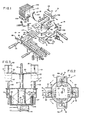
- the assembly 10 includes a rotary carousel II with a series of vertically reciprocable elevator platforms 12, the carousel assembly being rotatable on a central vertical shaft 13 driven by an indexing drive unit 14 at the base of the assembly 10.
- the drive unit 14 may be, for example, a Cameo No. 901 RDM-4-H32-330 with R250 reducer and I HP D.C. motor manufactured by Emerson Electric Company of Farmington, Connecticut.
- the case packing assembly 10 includes a plurality of stations for performing operations involving the carousel 11.
- articles 17 are loaded onto an adjacent elevator platform 12.
- the elevator platform 12 is caused to rise, loading the articles 17 into an empty case from the bottom (not shown in Figure 1).
- an offloading station 18 the articles, now loaded into a case, are removed from the carousel.
- an empty case 21 is opened from a flattened position in a storage stack and is held on the carousel, directly above an elevator platform 12, ready for advancement to the infeed station 16 where the assembled articles 17 are loaded.
- a pair of gripping arms 22 are positioned above each platform 12 of the carousel II.
- the arms 22 are connected to the central rotatable shaft 13, for example by a plate-like structure 23 that is secured to the shaft 13.
- Each pair of arms 22 preferably also includes a pair of top hold-down plates 20 secured to the arms to provide a positive stop to limit upward movement of a case 21 as articles on the platform 12 are moved upwardly into the case.
- the ring cam 27 has an upper surface which varies in height around its circumference, with smooth, curving transitions between levels.
- Each platform stem 26 supports a cam follower 29, preferably in the form of a wheel which rolls on the top surface of the ring cam 27, to effect the raising and lowering of the platform 12 in its travel with the carousel.
- each pair of arms 22 is permanently positioned above a platform 12, so that a case 21 may be held directly above a platform 12.
- the case-gripping arms 22 and the reciprocable platforms 12 are illustrated in greater detail in Figures 4, 6 and 7.
- Figure 4 shows one of the pairs of case-gripping arms 22, which extend from the rotatable structure 23.
- the arms 22 preferably include pressure bars 31 at least one of which is urged inwardly by springs 32 to grip a case 21 at a predetermined pressure.
- Position stops 33, secured to the arms 22 ensure that the case 21 is retained in precisely the desired position.
- a case 21 is drawn into the desired position by suction cups 34 that are attached to a reciprocating frame 36 shown in Figure 5.
- the suction cups 34 are positioned to engage the case as indicated in Figure 5 and apply suction to a panel of the case to grip this positively and then to pull the case into position between the pressure bars 31 by the retraction of the frame 36.
- the frame 36 is actuated by a fluid cylinder 37 (the frame 36 is actually positioned closer to a stack of flattened cases, on the other side of the carousel's central shaft 13 than is indicated in Figure I but is shown further removed, for clarity).
- FIGs 6 and 7 illustrate the camming mechanism for raising and lowering the elevator platforms 12.
- Each platform 12 is supported on its stem 26, which is mounted for vertical reciprocation with respect to the rotatable disc 24.
- a stem mounting and stabilizing structure 38 is secured to and extends downwardly from the disc 24, and has bearings or guides 39 within which the stem 26 is movable.
- a cam follower 41 in the form of a roller which rolls along the top edge of the ring cam 27, is connected to the stem 26.
- Cooperation of the cam follower with the rings 27, effects vertical reciprocation of the platforms 12 as the carousel 11 rotates, achieving the desired level for each platform 12 at each station as the carousel is indexed.
- the sides of the bearings 39 which face the ring cam 27 are open so that the cam follower 41 can travel up to its maximum-height position, as indicated in Figure 7 and in dashed lines in Figure 6.
- Each stem 26 further includes a second roller 42, that is co-axially mounted with the cam follower roller 41 but rotates independently thereof.
- the roller 42 travels in a vertical track 43 and acts to assure stability and fixed orientation of the stem 26 and platform 12 as the carousel is indexed.
- the roller track 43 is connected at its bottom end to a bottom disc or plate 44, that is co-rotatable with the central shaft 13 and the disc 24, and at its top end to the bottom of the disc 24.
- An enclosure structure 49 is preferably secured to the disc 24 at each elevator platform 12, to enclose three sides of the platform and thus to assure that the articles 17 enter the case 21 smoothly, i.e. without catching on any edges of the bottom of the open case.
- Two sides of the enclosure 49 are shown in Figure 6, on the left and at the back of the platforms (as viewed, for example, from the infeed station 16).
- a downwardly angled flap guide 55 at the back of the platform 12 extends through a back portion 49a of the enclosure, therebeing a vertical opening in the back portion 49a for that purpose.
- the right side of the enclosure 49 is not shown in Figure 6.
- a series of pivotal guide tabs 49b are mounted at the top edges of the enclosure 49, and also one at the front as indicated, connected to a bar 49c which spans between the two sides of the enclosure 49 at the front end thereof. These tabs 49b are caused to pivot upwardly as the articles on the platform move up into the case 21.
- the tabs 49b pivot up to engage inside surfaces of the bottom flaps of the case, that depend from the case during loading, to assure that the articles travel smoothly into the case.
- recesses 49d are formed in the platform 12 to permit the platform 12 to descend past the tabs 49b on its way back down, since the tabs 49d will then have fallen back to their inwardly-extending position shown in Figure 6.
- the recesses 49d in the platforms may be eliminated, so that articles do not fall through the recesses in which case the pivotal tabs 49b may be so powered as to be in the "up" position when the platform 12 returns past them.
- the enclosure structure 49 may also include an angled guide 49e connected to the bar 49c for assuring the products enter the case properly.
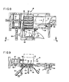
- FIG. 8 and the elevation view of Figure 9 illustrate a case 21 at the offloading station 18 at which point the case is filled with articles and the platform 12 is retained within the carton at the same level as, or slightly higher than, a set of rollers 50.
- the bottom flaps of the case namely, bottom side flaps 2ta and a bottom leading flap and a bottom trailing flap 54 as will be defined further hereinbelow, depend from the body of the carton.
- fluid-actuated flap-folding pushers 51 provided at each side and below the case extend to push bottom side flops, preferably minor flaps 21a of the carton, up into a closed position, i.e. against the bottom of the platform.
- the stem 26 of the platform is positioned between the edges of the bottom minor flaps 21a at this point, permitting sliding movement of the case parallel to those flap edges.
- the loaded case 21 may then be moved from the ptatform, by the action a pushing hook 52, as shown in Figures 8 and 9, onto the rollers 50.
- the pushing hook 52 is moved by a fluid actuated cylinder 53. Movement of the case onto the rollers causes a leading bottom flap of the case (not seen in Figures 8 and 9) i.e. the depending flap closest to the rollers 50, to be pushed upwardly towards a closed position, against the minor flaps.
- the loaded case After the loaded case reaches the dashed-line position shown in Figure 8, it is conveyed to a position wherein the bottom flap 54 is folded upwardly and closed. For example, by an inclined rail 58 positioned in the path of travel of the loaded carton, whereafter the top flaps of the case are closed, and all of the flaps sealed.
- case loading apparatus of the invention is illustrated and described herein with a four-position carousel, and with three operative stations and one inoperative station spaced 90° apart, fewer stations and carousel positions could be used if desired.
- the storage and pickup station 19 combined at the same position as the article infeed station 16
- a stack of cases being positioned above the article infeed station - the carousel would then require only two platforms with associated pairs of carton-holding arms, and only two index positions for the carousel: article and case infeed; and carton offloading.
- the apparatus operates more smoothly and is capable of higher speeds if a four-position carousel is used.
- the four position arrangement also affords more space for the various operative components, storage of cases, etc.
- the apparatus Whilst the apparatus is described and shown with the ring cam 27 effecting up and down movement of the elevator platforms, it is also possible for the platforms 12 to remain at a constant level, the case holding arms being movable to bring a case over articles accumulated on a platform. For reasons of space and the desired location of major working components at a low level, the illustrated arrangement of raising the platform and articles up into the case is presently preferred.
- the drive unit 14 On starting the apparatus, the drive unit 14 begins to rotate, removing pressure from a limit switch 101 which interacts with a cam on a shaft 100 extending from the drive unit 14, the shaft 100 and cam being included in the Cameo unit referenced above.
- the shaft 100 may be geared to rotate one full revolution for each 90° of rotation of the carousel, the drive unit 14 being brought to a stop each time the limit switch 101 is re-engaged.
- the case opening cylinder 37 at the case pickup station 19 is actuated to extend the frame 36 with the suction cups 34.
- the suction cups move toward the stack of flattened cases 21, and when the suction frame 36 is extended far enough to reach the first case 21 in the stack 21a a limit switch 103 is tripped, stopping further extension of the cylinder 37 and causing case-holding stops 105 to be opened by an actuating cylinder 106.
- the case opening cylinder 37 retracts, pulling with it a case 21.
- the case is opened by contact with a fixed curved rail 107, the opened case being positioned between and gripped by the arms 22 with their spring loaded pressure bars 31, as shown in Figure 4.
- Another limit switch 108 is actuated as the case opening cylinder 37 approaches full retraction, causing the vacuum to the suction cups to be shut off and the case holding stops 105 to be closed.
- a hinge plate II2 is pivoted up by a cylinder 113, bridging the gap between the accumulated articles and the platform 12.
- a product push-off cylinder II4 extends thereby releasing a switch 116, to move the articles 17 onto the elevator platform 12 (and into the enclosure 49 as shown in Figure 6) and beneath the open case.
- a limit switch II7 is actuated at the end of the stroke of the pusher cylinder 114, causing the cylinder to retract and the hinge plate 112 to pivot down. More product may then be accumulated on the table III of the infeed station.
- the bottom flap folding pushers 51 extend to fold the minor flaps of the case upwardly.
- the pusher hook cylinder 53 extends to discharge the filled case onto the rollers 50 which are preferably powered to draw the case off the carousel and move it into position for further operations.
- This movement of the pusher hook assembly eventually actuates a switch 118 which causes the hook cylinder 53 to retract and the bottom flap folding pushers 51 to retract.
- the powered rollers 50 and the case pusher 56 and cylinder 57 ( Figure 8 and Figure I) then act to move the filled case to the sealing section.
- the drive unit 14 will rotate to index the carousel, releasing the limit switch 101.
- the limit switch 102 will be actuated, restarting all of the above-described operations. Re-engagement of the limit switch 10 casing the indexer to stop at the next position.
Landscapes
- Engineering & Computer Science (AREA)
- Mechanical Engineering (AREA)
- Container Filling Or Packaging Operations (AREA)
- Supplying Of Containers To The Packaging Station (AREA)
Applications Claiming Priority (2)
| Application Number | Priority Date | Filing Date | Title |
|---|---|---|---|
| US06/432,965 US4481752A (en) | 1982-10-05 | 1982-10-05 | Rotary case loading machine |
| US432965 | 1982-10-05 |
Publications (3)
| Publication Number | Publication Date |
|---|---|
| EP0105104A2 true EP0105104A2 (de) | 1984-04-11 |
| EP0105104A3 EP0105104A3 (en) | 1985-05-02 |
| EP0105104B1 EP0105104B1 (de) | 1986-11-26 |
Family
ID=23718290
Family Applications (1)
| Application Number | Title | Priority Date | Filing Date |
|---|---|---|---|
| EP83106952A Expired EP0105104B1 (de) | 1982-10-05 | 1983-07-15 | Verfahren und Vorrichtung zum Einladen von Artikeln in Schachteln |
Country Status (5)
| Country | Link |
|---|---|
| US (1) | US4481752A (de) |
| EP (1) | EP0105104B1 (de) |
| AU (1) | AU551355B2 (de) |
| CA (1) | CA1207293A (de) |
| DE (1) | DE3367887D1 (de) |
Cited By (4)
| Publication number | Priority date | Publication date | Assignee | Title |
|---|---|---|---|---|
| EP0358540A1 (de) * | 1988-09-09 | 1990-03-14 | Newtec International | Verfahren und Anlage zum Zusammensetzen eines Pakets aus einer Vielzahl von Gegenständen mit inneren Trennelementen und die aussen von einem, eine Schachtel bildenden Wickel umgeben sind |
| GB2224256A (en) * | 1988-10-26 | 1990-05-02 | Samsung Electronics Co Ltd | A box-flap folding device |
| US5022214A (en) * | 1988-10-26 | 1991-06-11 | Samsung Electronics Co., Ltd. | Packaging machine with box-flap folding device |
| WO1997006061A1 (de) * | 1995-08-04 | 1997-02-20 | Dividella Ag | Verfahren und vorrichtung zum herstellen und beschicken einer verpackung, sowie verpackung |
Families Citing this family (19)
| Publication number | Priority date | Publication date | Assignee | Title |
|---|---|---|---|---|
| US4644734A (en) * | 1985-02-08 | 1987-02-24 | Hartness Thomas Signor | Case packer |
| US4674261A (en) * | 1986-06-25 | 1987-06-23 | Sabel Herbert John | Machine for loading and closing a shipping case with a telescopic lid |
| KR100471125B1 (ko) * | 1997-11-27 | 2005-06-07 | 삼성전자주식회사 | 반도체 패키지 운반용 튜브의 자동 포장 방법 및장치 |
| US6912775B1 (en) * | 1998-02-25 | 2005-07-05 | Seagate Technology Llc | Assembly device for assembling components |
| US7191578B2 (en) * | 1999-10-14 | 2007-03-20 | Stewart Systems, Inc. | Pattern former for wrapped bakery products and bakery tray loading system |
| US7305806B2 (en) * | 1999-10-14 | 2007-12-11 | Stewart Systems, Inc. | Pattern former for wrapped bakery products and method for loading and unloading bakery products |
| US6401435B1 (en) * | 1999-10-14 | 2002-06-11 | Sasib North America, Inc. | Pattern former and method of pattern forming for wrapped bakery products |
| US6862869B2 (en) * | 1999-10-14 | 2005-03-08 | Stewart Systems, Inc. | Pattern former for wrapped bakery products |
| NL1014519C2 (nl) * | 2000-02-29 | 2001-08-30 | Rompa Patent Beheer B V | Installatie voor het snijden en verpakken van brood. |
| WO2002092481A1 (en) * | 2001-05-14 | 2002-11-21 | F.R. Drake Company | System and method of processing and packing disk-like objects |
| US7370456B2 (en) * | 2002-05-09 | 2008-05-13 | Fujifilm Corporation | Packaging object supplying apparatus, box body supplying apparatus, boxing apparatus, packaging system and packaging method |
| US7401453B2 (en) * | 2004-09-02 | 2008-07-22 | Graphic Packaging International, Inc. | Packaging system having loading carousel |
| DE602005010887D1 (de) * | 2004-09-02 | 2008-12-18 | Graphic Packaging Int Inc | Verpackungssystem mit ladekarussell |
| US20070204567A1 (en) * | 2006-03-03 | 2007-09-06 | R.A. Jones & Co. Inc. | Top load cartoner |
| MX390373B (es) | 2015-05-29 | 2025-03-20 | Graphic Packaging Int Llc | Sistema de embalaje |
| DE102019113144A1 (de) * | 2019-05-17 | 2020-11-19 | Illinois Tool Works Inc. | Verpackungsmaschine zum verpacken von produkten in kartons und verfahren hierfür |
| CN110589077B (zh) * | 2019-08-30 | 2020-07-24 | 华中科技大学 | 一种条帽旋转包装装置 |
| WO2023094998A1 (en) * | 2021-11-24 | 2023-06-01 | R.A Jones & Co. | Process and apparatus for shaping a box by wrapping around |
| WO2023094997A1 (en) * | 2021-11-24 | 2023-06-01 | R.A Jones & Co. | Apparatus and process for shaping a box by wrapping-around |
Family Cites Families (6)
| Publication number | Priority date | Publication date | Assignee | Title |
|---|---|---|---|---|
| US3605377A (en) * | 1970-02-25 | 1971-09-20 | Sabel Herbert John | Carton loading machine |
| US3751872A (en) * | 1971-09-27 | 1973-08-14 | Container Corp | Apparatus and method for enclosing of container groups |
| DE2209370C3 (de) * | 1972-02-28 | 1979-04-12 | Focke & Pfuhl, 3090 Verden | Vorrichtung zum Aufschieben von faltbaren Behältern auf Gegenstandsgruppen |
| US3923144A (en) * | 1974-03-18 | 1975-12-02 | Langen H J & Sons Ltd | Intermittent load accumulator |
| US4179866A (en) * | 1978-04-03 | 1979-12-25 | R. A. Pearson Company | Case packer |
| FR2493805B1 (fr) * | 1980-11-07 | 1985-09-06 | Thimon Ets | Procede et machine pour constituer, remplir, fermer un contenant de forme generale parallelepipedique a partir d'une forme aplatie |
-
1982
- 1982-10-05 US US06/432,965 patent/US4481752A/en not_active Expired - Lifetime
-
1983
- 1983-04-08 CA CA000425515A patent/CA1207293A/en not_active Expired
- 1983-06-22 AU AU16139/83A patent/AU551355B2/en not_active Ceased
- 1983-07-15 DE DE8383106952T patent/DE3367887D1/de not_active Expired
- 1983-07-15 EP EP83106952A patent/EP0105104B1/de not_active Expired
Cited By (6)
| Publication number | Priority date | Publication date | Assignee | Title |
|---|---|---|---|---|
| EP0358540A1 (de) * | 1988-09-09 | 1990-03-14 | Newtec International | Verfahren und Anlage zum Zusammensetzen eines Pakets aus einer Vielzahl von Gegenständen mit inneren Trennelementen und die aussen von einem, eine Schachtel bildenden Wickel umgeben sind |
| FR2636306A1 (fr) * | 1988-09-09 | 1990-03-16 | Newtec Int | Procede et installation pour constituer un paquet comportant plusieurs objets juxtaposes separes par un cloisonnement interne et entoures exterieurement d'une enveloppe formant caisse |
| GB2224256A (en) * | 1988-10-26 | 1990-05-02 | Samsung Electronics Co Ltd | A box-flap folding device |
| US5022214A (en) * | 1988-10-26 | 1991-06-11 | Samsung Electronics Co., Ltd. | Packaging machine with box-flap folding device |
| GB2224256B (en) * | 1988-10-26 | 1992-11-18 | Samsung Electronics Co Ltd | A box-flap folding device |
| WO1997006061A1 (de) * | 1995-08-04 | 1997-02-20 | Dividella Ag | Verfahren und vorrichtung zum herstellen und beschicken einer verpackung, sowie verpackung |
Also Published As
| Publication number | Publication date |
|---|---|
| EP0105104A3 (en) | 1985-05-02 |
| DE3367887D1 (en) | 1987-01-15 |
| AU1613983A (en) | 1984-04-12 |
| EP0105104B1 (de) | 1986-11-26 |
| AU551355B2 (en) | 1986-04-24 |
| CA1207293A (en) | 1986-07-08 |
| US4481752A (en) | 1984-11-13 |
Similar Documents
| Publication | Publication Date | Title |
|---|---|---|
| EP0105104B1 (de) | Verfahren und Vorrichtung zum Einladen von Artikeln in Schachteln | |
| US5105600A (en) | Flexible apparatus and method for erecting and loading cases | |
| US4067172A (en) | Carton set-up and loading machine | |
| US5341626A (en) | Cartoning method and apparatus | |
| US2684799A (en) | Casing machine | |
| US4037734A (en) | Method and apparatus for depalletizing | |
| US3757486A (en) | Apparatus for packing objects in a carton | |
| JPH06135420A (ja) | カートニング装置 | |
| US4583965A (en) | Assembly for unfolding flattened cartons in packaging machinery | |
| US4930977A (en) | Envelope handling system | |
| CN105173216A (zh) | 布袋包装机 | |
| EP0488794B1 (de) | Stapelvorrichtung | |
| CN210971752U (zh) | 包装设备 | |
| US4122939A (en) | Load transfer mechanism for packaging machine | |
| EP0495580A1 (de) | Vorrichtung zum Zählen und Füllen in Beutel von in mehreren Reihen zugeführten Gegenständen | |
| US5088720A (en) | Envelope handling system | |
| US3624723A (en) | Automatic bag accumulating, advancing and charging apparatus | |
| CN210971751U (zh) | 包装设备 | |
| CN109665150B (zh) | 容器和盖的按层接料装箱装置 | |
| JPS6099838A (ja) | 缶端部等から袋を自動的に剥ぎ取る方法と装置 | |
| US6401434B1 (en) | Method and apparatus for loading filled fruit packing trays | |
| US4452031A (en) | Automatic card dispenser and pick-off assembly | |
| US4949835A (en) | Envelope handling system | |
| CN213769171U (zh) | 一种套袋包装机 | |
| DK171675B1 (da) | Apparat til opbevaring og udlevering af materialer i arkform |
Legal Events
| Date | Code | Title | Description |
|---|---|---|---|
| PUAI | Public reference made under article 153(3) epc to a published international application that has entered the european phase |
Free format text: ORIGINAL CODE: 0009012 |
|
| AK | Designated contracting states |
Designated state(s): DE FR GB NL |
|
| PUAL | Search report despatched |
Free format text: ORIGINAL CODE: 0009013 |
|
| AK | Designated contracting states |
Designated state(s): DE FR GB NL |
|
| 17P | Request for examination filed |
Effective date: 19850502 |
|
| GRAA | (expected) grant |
Free format text: ORIGINAL CODE: 0009210 |
|
| AK | Designated contracting states |
Kind code of ref document: B1 Designated state(s): DE FR GB NL |
|
| REF | Corresponds to: |
Ref document number: 3367887 Country of ref document: DE Date of ref document: 19870115 |
|
| ET | Fr: translation filed | ||
| PLBE | No opposition filed within time limit |
Free format text: ORIGINAL CODE: 0009261 |
|
| STAA | Information on the status of an ep patent application or granted ep patent |
Free format text: STATUS: NO OPPOSITION FILED WITHIN TIME LIMIT |
|
| 26N | No opposition filed | ||
| PGFP | Annual fee paid to national office [announced via postgrant information from national office to epo] |
Ref country code: FR Payment date: 19990709 Year of fee payment: 17 |
|
| PGFP | Annual fee paid to national office [announced via postgrant information from national office to epo] |
Ref country code: GB Payment date: 19990714 Year of fee payment: 17 |
|
| PGFP | Annual fee paid to national office [announced via postgrant information from national office to epo] |
Ref country code: DE Payment date: 19990716 Year of fee payment: 17 |
|
| PGFP | Annual fee paid to national office [announced via postgrant information from national office to epo] |
Ref country code: NL Payment date: 19990730 Year of fee payment: 17 |
|
| PG25 | Lapsed in a contracting state [announced via postgrant information from national office to epo] |
Ref country code: GB Free format text: LAPSE BECAUSE OF NON-PAYMENT OF DUE FEES Effective date: 20000715 |
|
| PG25 | Lapsed in a contracting state [announced via postgrant information from national office to epo] |
Ref country code: NL Free format text: LAPSE BECAUSE OF NON-PAYMENT OF DUE FEES Effective date: 20010201 |
|
| GBPC | Gb: european patent ceased through non-payment of renewal fee |
Effective date: 20000715 |
|
| PG25 | Lapsed in a contracting state [announced via postgrant information from national office to epo] |
Ref country code: FR Free format text: LAPSE BECAUSE OF NON-PAYMENT OF DUE FEES Effective date: 20010330 |
|
| NLV4 | Nl: lapsed or anulled due to non-payment of the annual fee |
Effective date: 20010201 |
|
| REG | Reference to a national code |
Ref country code: FR Ref legal event code: ST |
|
| PG25 | Lapsed in a contracting state [announced via postgrant information from national office to epo] |
Ref country code: DE Free format text: LAPSE BECAUSE OF NON-PAYMENT OF DUE FEES Effective date: 20010501 |