EP0105087A2 - Digital filter for a remote control receiver - Google Patents
Digital filter for a remote control receiver Download PDFInfo
- Publication number
- EP0105087A2 EP0105087A2 EP83105834A EP83105834A EP0105087A2 EP 0105087 A2 EP0105087 A2 EP 0105087A2 EP 83105834 A EP83105834 A EP 83105834A EP 83105834 A EP83105834 A EP 83105834A EP 0105087 A2 EP0105087 A2 EP 0105087A2
- Authority
- EP
- European Patent Office
- Prior art keywords
- filter
- frequency
- digital filter
- zeros
- digital
- Prior art date
- Legal status (The legal status is an assumption and is not a legal conclusion. Google has not performed a legal analysis and makes no representation as to the accuracy of the status listed.)
- Granted
Links
Images


Classifications
-
- H—ELECTRICITY
- H03—ELECTRONIC CIRCUITRY
- H03H—IMPEDANCE NETWORKS, e.g. RESONANT CIRCUITS; RESONATORS
- H03H17/00—Networks using digital techniques
- H03H17/02—Frequency selective networks
- H03H17/04—Recursive filters
-
- H—ELECTRICITY
- H02—GENERATION; CONVERSION OR DISTRIBUTION OF ELECTRIC POWER
- H02J—CIRCUIT ARRANGEMENTS OR SYSTEMS FOR SUPPLYING OR DISTRIBUTING ELECTRIC POWER; SYSTEMS FOR STORING ELECTRIC ENERGY
- H02J13/00—Circuit arrangements for providing remote indication of network conditions, e.g. an instantaneous record of the open or closed condition of each circuitbreaker in the network; Circuit arrangements for providing remote control of switching means in a power distribution network, e.g. switching in and out of current consumers by using a pulse code signal carried by the network
- H02J13/00006—Circuit arrangements for providing remote indication of network conditions, e.g. an instantaneous record of the open or closed condition of each circuitbreaker in the network; Circuit arrangements for providing remote control of switching means in a power distribution network, e.g. switching in and out of current consumers by using a pulse code signal carried by the network characterised by information or instructions transport means between the monitoring, controlling or managing units and monitored, controlled or operated power network element or electrical equipment
- H02J13/00007—Circuit arrangements for providing remote indication of network conditions, e.g. an instantaneous record of the open or closed condition of each circuitbreaker in the network; Circuit arrangements for providing remote control of switching means in a power distribution network, e.g. switching in and out of current consumers by using a pulse code signal carried by the network characterised by information or instructions transport means between the monitoring, controlling or managing units and monitored, controlled or operated power network element or electrical equipment using the power network as support for the transmission
- H02J13/00009—Circuit arrangements for providing remote indication of network conditions, e.g. an instantaneous record of the open or closed condition of each circuitbreaker in the network; Circuit arrangements for providing remote control of switching means in a power distribution network, e.g. switching in and out of current consumers by using a pulse code signal carried by the network characterised by information or instructions transport means between the monitoring, controlling or managing units and monitored, controlled or operated power network element or electrical equipment using the power network as support for the transmission using pulsed signals
-
- Y—GENERAL TAGGING OF NEW TECHNOLOGICAL DEVELOPMENTS; GENERAL TAGGING OF CROSS-SECTIONAL TECHNOLOGIES SPANNING OVER SEVERAL SECTIONS OF THE IPC; TECHNICAL SUBJECTS COVERED BY FORMER USPC CROSS-REFERENCE ART COLLECTIONS [XRACs] AND DIGESTS
- Y02—TECHNOLOGIES OR APPLICATIONS FOR MITIGATION OR ADAPTATION AGAINST CLIMATE CHANGE
- Y02B—CLIMATE CHANGE MITIGATION TECHNOLOGIES RELATED TO BUILDINGS, e.g. HOUSING, HOUSE APPLIANCES OR RELATED END-USER APPLICATIONS
- Y02B90/00—Enabling technologies or technologies with a potential or indirect contribution to GHG emissions mitigation
- Y02B90/20—Smart grids as enabling technology in buildings sector
-
- Y—GENERAL TAGGING OF NEW TECHNOLOGICAL DEVELOPMENTS; GENERAL TAGGING OF CROSS-SECTIONAL TECHNOLOGIES SPANNING OVER SEVERAL SECTIONS OF THE IPC; TECHNICAL SUBJECTS COVERED BY FORMER USPC CROSS-REFERENCE ART COLLECTIONS [XRACs] AND DIGESTS
- Y02—TECHNOLOGIES OR APPLICATIONS FOR MITIGATION OR ADAPTATION AGAINST CLIMATE CHANGE
- Y02E—REDUCTION OF GREENHOUSE GAS [GHG] EMISSIONS, RELATED TO ENERGY GENERATION, TRANSMISSION OR DISTRIBUTION
- Y02E60/00—Enabling technologies; Technologies with a potential or indirect contribution to GHG emissions mitigation
-
- Y—GENERAL TAGGING OF NEW TECHNOLOGICAL DEVELOPMENTS; GENERAL TAGGING OF CROSS-SECTIONAL TECHNOLOGIES SPANNING OVER SEVERAL SECTIONS OF THE IPC; TECHNICAL SUBJECTS COVERED BY FORMER USPC CROSS-REFERENCE ART COLLECTIONS [XRACs] AND DIGESTS
- Y04—INFORMATION OR COMMUNICATION TECHNOLOGIES HAVING AN IMPACT ON OTHER TECHNOLOGY AREAS
- Y04S—SYSTEMS INTEGRATING TECHNOLOGIES RELATED TO POWER NETWORK OPERATION, COMMUNICATION OR INFORMATION TECHNOLOGIES FOR IMPROVING THE ELECTRICAL POWER GENERATION, TRANSMISSION, DISTRIBUTION, MANAGEMENT OR USAGE, i.e. SMART GRIDS
- Y04S40/00—Systems for electrical power generation, transmission, distribution or end-user application management characterised by the use of communication or information technologies, or communication or information technology specific aspects supporting them
- Y04S40/12—Systems for electrical power generation, transmission, distribution or end-user application management characterised by the use of communication or information technologies, or communication or information technology specific aspects supporting them characterised by data transport means between the monitoring, controlling or managing units and monitored, controlled or operated electrical equipment
- Y04S40/121—Systems for electrical power generation, transmission, distribution or end-user application management characterised by the use of communication or information technologies, or communication or information technology specific aspects supporting them characterised by data transport means between the monitoring, controlling or managing units and monitored, controlled or operated electrical equipment using the power network as support for the transmission
Definitions
- the receiver-side recovery of the remote control signals or remote control commands which are fed to the remote control receiver on the input side together with the mains voltage, its harmonics and any other interference frequencies, are preferably cascades of LC or active second order RC filters.
- Such filters are designed as narrow band passes.
- the quality factor Q is usually around 30, so that the relatively weak remote control signal of, for example, about 1 to 8 volts can be filtered out of the low-voltage network of, for example, 220 V 50 Hz, which in some cases carries considerable interference signals, for evaluation. Compare for example CH PS-607 467.
- the present invention is therefore based on the object of providing a digital filter suitable for remote control receivers, in particular ripple control apparatuses, in which, despite the use of an arithmetic unit (microcomputer) having a dynamic of only 8 bits, the above-mentioned overloads (overflow) no longer occur and one for which intended application suitable pass characteristic of the digital filter is realized.
- arithmetic unit microcomputer
- the filter characteristic of such a digital filter can basically be designed in the same frequency range as is the case with the conventional analog filters, i.e. the same amplitude response and phase response are achieved as with these.
- a price-determining factor is the so-called bit number of the microcomputer. In the present case, this means the length of the data words used, ie the number of binary digits per number.
- the values summarized in Table 1 are common today. The bit number defines the computing dynamics of the microcomputer or arithmetic unit.
- FIG. 2 shows a structure of a second-order digital filter stage.
- the resonance frequency gain vg of the filter stage also increases with an increase in the filter quality Q and with an increase in the sampling rate (ratio of the sampling frequency f s to the resonance frequency fg).
- the invention is based on the following solution: Given the requirement for a high quality of the narrow bandpass filter and for a low computing effort, a suitable filter structure is selected, e.g. a so-called fourth-order recursive filter, implemented as a cascade of two second-order recursive filters according to FIG. 1. The problem of the high resonance frequency gain of the individual stages is countered by the targeted placement of zeros in the vicinity of the resonance frequency.
- a suitable filter structure is selected, e.g. a so-called fourth-order recursive filter, implemented as a cascade of two second-order recursive filters according to FIG. 1.
- the problem of the high resonance frequency gain of the individual stages is countered by the targeted placement of zeros in the vicinity of the resonance frequency.
- the first stage is given a passage characteristic roughly according to FIG. 3, and the second stage is given a passage characteristic roughly according to FIG. 4.
- a total passage characteristic then results roughly according to FIG. 5 over both stages in cascade.
- FIGS. 3, 4 and 5 mark the Arrows the position of the zeros.
- Both stages have a resonance frequency gain of 34 dB (factor 55).
- the divider has a division ratio of 1:55 (- 34 dB). The maximum signal boost of the first stage is thus scaled back to the value 1.
- Curve B in FIG. 6 shows the amplitude response of a filter (according to FIG. 1), the first filter stage having a zero 10% below the resonance frequency and the second filter stage having a zero 10% above the resonance frequency.
- the amplitude response of the first stage is shown in FIG. 3, that of the second stage in FIG. 4. With these shifted zeros it is achieved that the resonance frequency gain per filter stage is only approx. 14 dB (factor 5) in contrast to 34 dB ( Factor 55) to the filter mentioned above.
- the divider between the filter stages has a ratio of 1: 5 in this case.
- the filter has equally good or even slightly better properties in the near-selective range, but in the wide range it has a finite attenuation of approx. - 27 dB, based on the Resonance frequency.
- a digital filter according to the invention which is suitable for a ripple control receiver, for example, has the following characteristic values shown in Table 5.
- the ratio of the interference frequencies to the useful frequency is 150/167 and 184/167, which corresponds to the factors 0.9 and 1.1. These conditions are favorable because the main interference frequencies are just f + 10%. Since the zeros introduced in this way can be freely selected in the range from about f + 10 to f + 20% g - g - , it proves to be particularly advantageous to place them exactly on the main interference frequencies, which means that the filter becomes much less sensitive, especially to these main interference frequencies. This measure also leads to a significant technical improvement of the filter.
- a suitable digital filter for remote control receivers is therefore basically designed. In further steps, it only has to can still be optimized according to the known rules of art. (Scaling, limiting the word length of the coefficients, for example) This is done according to the instructions in the references mentioned.
- the digital filter is then programmed into the arithmetic unit according to the instructions of the arithmetic unit manufacturer and embedded in any other programs that may be used, which are preferably used to evaluate the filter output.
Abstract
Description
In konventionellen elektronischen oder elektromechanischen Fernsteuerempfängern, wie sie beispielsweise in Rundsteuersystemen zur Anwendung gelangen, werden für die empfängerseitige Rückgewinnung der Fernsteuersignale bzw. Fernsteuerbefehle, welche zusammen mit der Netzspannung, deren Harmonischen und allenfalls weiteren Störfrequenzen dem Fernsteuerempfänger eingangsseitig zugeführt werden, vorzugsweise Kaskaden von LC-oder aktiven RC-Filtern zweiter Ordnung angewendet.In conventional electronic or electromechanical remote control receivers, such as those used in ripple control systems, the receiver-side recovery of the remote control signals or remote control commands, which are fed to the remote control receiver on the input side together with the mains voltage, its harmonics and any other interference frequencies, are preferably cascades of LC or active second order RC filters.
Solche Filter sind dabei als schmale Bandpässe ausgebildet. Der Gütefaktor Q liegt üblicherweise bei etwa 30, damit das relativ schwache Fernsteuersignal von beispielsweise etwa 1 bis 8 Volt aus dem zum Teil sehr beträchtlichen Störsignale führenden Niederspannungsnetz von beispielsweise 220 V 50 Hz für die Auswertung herausgefiltert werden kann. Vergleiche hiezu beispielsweise CH PS-607 467.Such filters are designed as narrow band passes. The quality factor Q is usually around 30, so that the relatively weak remote control signal of, for example, about 1 to 8 volts can be filtered out of the low-voltage network of, for example, 220 V 50 Hz, which in some cases carries considerable interference signals, for evaluation. Compare for example CH PS-607 467.
Als Störfrequenzen treten die Netzspannung mit 220 V und ihre Harmonischen mit Spannungen von normalerweise bis etwa 15 Volt und gelegentlich sogar noch etwas mehr auf. Siehe hiezu die Publikation VDEW: Empfehlung für die Frequenzplanung bei Frequenz-Rundsteueranlagen, Verlags- und Wirtschaftsgesellschaft der Elektrizitätswerke mbH, 6 Frankfurt (Main) 1970.The mains voltage with 220 V and its harmonics with voltages of normally up to about 15 volts and occasionally even a little more occur as interference frequencies. See the publication VDEW: Recommendation for frequency planning for frequency ripple control systems, publishing and business society of Elektrizitätswerke mbH, 6 Frankfurt (Main) 1970.
Es ist schon ein Verfahren und eine Vorrichtung zur Fernübertragung von Signalen vorgeschlagen worden, bei welchem ein Abtastfilter in der Form eines Digitalbandpasses vorgesehen ist, siehe CH PS 559 983.A method and a device for the remote transmission of signals has already been proposed, in which a scanning filter in the form of a digital band pass is provided, see CH PS 559 983.
Weiterhin ist ein elektronischer Rundsteuerempfänger vorgeschlagen worden, siehe DOS 2 708 074, ohne dass darin jedoch nähere Angaben über das Digitalfilter gemacht werden.Furthermore, an electronic ripple control receiver has been proposed, see DOS 2 708 074, without however giving any details about the digital filter.
Bei der Anwendung eines Digitalfilters,unter Benutzung eines Mikrocomputers als Rechenwerk für einen Rundsteuerempfänger treten Schwierigkeiten auf, wenn die von der Anwendung her geforderten Filtereigenschaften wirtschaftlich gelöst werden sollen. Insbesondere tritt die Schwierigkeit auf, dass mit den wirtschaftlich günstigen 8-Bit-Rechenwerken (Mikrocomputer) ein passendes Digitalfilter nicht ohne besondere Massnahmen realisiert werden kann.Difficulties arise when using a digital filter using a microcomputer as arithmetic unit for a ripple control receiver if the filter properties required by the application are to be economically solved. In particular, there is the difficulty that a suitable digital filter cannot be implemented without special measures using the economically advantageous 8-bit arithmetic units (microcomputers).
Unter Berücksichtigung der von der Anwendung her verlangten Dynamik kann dann ein bekanntes analoges Filter für Fernsteuerempfänger nicht ohne weiteres "nach allgemein bekannten Regeln in ein digitales Filter transformiert werden". Durch eine filterinterne Anhebung des Nutzsignals, das heisst des Fernsteuersignals, neigt nämlich ein 8-Bit-Rechenwerk bereits zum Uebersteuern (Overflow), und dies selbst wenn noch kein Störsignal auftritt. Im Hinblick auf die praktisch vorkommenden Nutzsignal-/Störsignal-Verhältnisse allein würde zwar ein 8-Bit-Rechenwerk für die Signalverarbeitung eine gerade noch ausreichende Dynamik aufweisen. In der Praxis zeigt sich jedoch, dass die erwähnte Signalanhebung die einwandfreie Arbeitsweise des Filters in Frage stellt. Die dadurch hervorgerufene Uebersteuerung innerhalb der Filterstufen ist auch eine Folge der aus praktischen Erfordernissen verlangten Gütefaktoren Q von etwa 30 und der in der Praxis verlangten Abtastraten (Verhältnis von Abtastfrequenz des Eingangssignales und der Resonanzfrequenz) von mindestens 2.Taking into account the dynamics required by the application, a known analog filter for remote control receivers cannot then simply be "transformed into a digital filter according to generally known rules". By means of a filter-internal increase in the useful signal, that is to say the remote control signal, an 8-bit arithmetic unit already tends to overflow, even if no interference signal occurs yet. In view of the practically occurring useful signal / interference signal ratios alone, an 8-bit arithmetic unit for signal processing would have just enough dynamics. In practice, however, it turns out that the signal boost mentioned questions the correct functioning of the filter. The resulting overdriving within the filter stages is also a consequence of the quality factors Q of about 30 required from practical requirements and the sampling rates required in practice (ratio of the sampling frequency of the input signal and the resonance frequency) of at least 2.
Der vorliegenden Erfindung liegt daher die Aufgabe zugrunde, ein für Fernsteuerempfänger, insbesondere Rundsteuerapparate geeignetes Digitalfilter zu schaffen, bei welchem trotz Verwendung eines eine Dynamik von nur 8 Bit aufweisenden Rechenwerkes (Mikrocomputer) die genannten Uebersteuerungen (Overflow) nicht mehr auftreten und wobei eine für die vorgesehene Anwendung geeignete Durchlasscharakteristik des Digitalfilters verwirklicht ist.The present invention is therefore based on the object of providing a digital filter suitable for remote control receivers, in particular ripple control apparatuses, in which, despite the use of an arithmetic unit (microcomputer) having a dynamic of only 8 bits, the above-mentioned overloads (overflow) no longer occur and one for which intended application suitable pass characteristic of the digital filter is realized.
Zur Lösung dieser Aufgabe dienen die in den Ansprüchen niedergelegten Massnahmen. Im folgenden wird die Erfindung anhand der Zeichnung beispielsweise erläutert, dabei zeigtThe measures set out in the claims serve to solve this task. In the following the invention is explained for example with reference to the drawing, which shows
- Fig. l eine Filterstruktur in Anlehnung an: "Theory and Application of Digital Signal Processing (Rabbiner/Gold), Prentice Hall International Inc. London 1975, Seite 41 und folgende";1 shows a filter structure based on: "Theory and Application of Digital Signal Processing (Rabbi / Gold), Prentice Hall International Inc. London 1975, page 41 and following";
- Fig. 2 eine schematische Darstellung einer digitalen Filterstufe 2. Ordnung mit Erläuterungen der einzelnen Symbole und der zugehörigen Uebertragungsfunktion;2 shows a schematic illustration of a second-order digital filter stage with explanations of the individual symbols and the associated transfer function;
- Fig. 3 eine Durchlasscharakteristik einer ersten Filterstufe;3 shows a pass characteristic of a first filter stage;
- Fig. 4 eine Durchlasscharakteristik einer zweiten Filterstufe;4 shows a pass characteristic of a second filter stage;
- Fig. 5 eine Gesamtdurchlasscharakteristik über beide Stufen gemäss Fig. 3 und Fig. 4 in Kaskade;5 shows a total transmission characteristic over both stages according to FIGS. 3 and 4 in cascade;
- Fig. 6 eine Gesamtdurchlasskurve mit Nullstellen bei + und - 10 % unterhalb bzw. oberhalb der gewünschten Empfangsfrequenz;6 shows a total transmission curve with zeros at + and - 10% below or above the desired reception frequency;
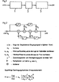
- Fig. 7 eine schematische Darstellung von kaskadierten Filterstufen zweiter Ordnung.Fig. 7 is a schematic representation of cascaded filter stages of the second order.
Zum Stande der Technik wird ausser den.bereits genannten Publikationen auch noch verwiesen auf das Buch "Halbleiter-Schalttechnik" (Tietze/Schenk) 5. Auflage, Springer-Verlag Berlin 1980 sowie Dissertation Nr. 5 645/1976 ETH Zürich: Probleme der Realisierung digitaler Filter, (F. Bonzanigo) sowie auf die Publikation "Theory and design of digital filters" Electronic Engineering May 1977, Morgan Grampian Limited, Calderwood Str. London SE 18 2 BP.With regard to the state of the art, in addition to the publications already mentioned, reference is also made to the book "Semiconductor Switching Technology" (Tietze / Schenk) 5th edition, Springer-Verlag Berlin 1980 and dissertation No. 5 645/1976 ETH Zurich: Problems of Realization digital filter, (F. Bonzanigo) and on the publication "Theory and design of digital filters" Electronic Engineering May 1977, Morgan Grampian Limited, Calderwood Str. London SE 18 2 BP.
Für die Anwendung eines digitalen Filters in einem Fernsteuerempfänger, insbesondere in einem Rundsteuerempfänger ist es sehr wichtig, dass die für die einwandfreie Arbeitsweise erforderliche Durchlasscharakteristik mit äusserster Wirtschaftlichkeit verwirklicht werden kann. Dabei wird es wohl preislich immer von Vorteil sein, ein Rechenwerk mit möglichst geringer Dynamik (z.B. nur 8 Bit) einsetzen zu können (z.B. Mikrocomputer mit 8-Bit-Rechenwerk).For the use of a digital filter in a remote control receiver, in particular in a ripple control receiver, it is very important that the passage characteristics required for the correct operation can be realized with the utmost economy. In terms of price, it will always be advantageous to be able to use an arithmetic unit with the lowest possible dynamic range (e.g. only 8 bits) (e.g. microcomputers with 8-bit arithmetic units).
Durch die Stabilisierung der Taktfrequenz, sei es beispielsweise mittels eines bekannten Quarzoszillators oder durch Bindung der Taktfrequenz an eine Referenzfrequenz, beispielsweise an die Netzfrequenz, kann mit sehr geringem Aufwand eine ausreichende Frequenzstabilität auch über eine lange Gebrauchsdauer erzielt werden.By stabilizing the clock frequency, for example by means of a known quartz oscillator or by binding the clock frequency to a reference frequency, for example to the mains frequency, sufficient frequency stability can be achieved over a long period of use with very little effort.
Die Filtercharakteristik eines solchen Digitalfilters kann in einem eingeschränkten, jedoch für die Praxis ausreichenden Frequenzbereich grundsätzlich gleich gestaltet werden wie bei den bisher üblichen analogen Filtern, d.h. man erreicht gleichen Amplitudengang und gleichen Phasengang wie bei diesen.The filter characteristic of such a digital filter can basically be designed in the same frequency range as is the case with the conventional analog filters, i.e. the same amplitude response and phase response are achieved as with these.
Für die Ausführung eines solchen Filters mittels eines Rechenwerkes (Mikrocomputer), beispielsweise nach DOS 2 708 074, müsste jedoch berücksichtigt werden, dass die digitale Filterung mit genügend geringem Aufwand an Rechenzeit im Rechenwerk realisiert werden muss, weil das System ja zeitecht betrieben werden muss.For the implementation of such a filter by means of an arithmetic unit (microcomputer), for example according to DOS 2 708 074, it would have to be taken into account that the digital filtering has to be implemented in the arithmetic unit with a sufficiently small amount of computing time because the system has to be operated in real time.
Zudem ist anzustreben, dass bereits ein Rechenwerk aus der Klasse der preisgünstigsten "Ein-Chip"-Mikrocomputer geeignet' ist. Ein preisbestimmender Faktor ist dabei die sogenannte Bit-Zahl des Mikrocomputers. Im vorliegenden Fall ist darunter die Länge der verwendeten Daten-Wörter gemeint, d.h. die Anzahl der binären Stellen pro Zahl. Ueblich sind heute die in Tabelle 1 zusammengefassten Werte.

Bezüglich der Rechengeschwindigkeit muss ebenfalls darauf geachtet werden, dass ein" kostengünstiges Standard-Produkt zur Anwendung kommen kann. Dies bedeutet, dass für das digitale Filter Minimalstrukturen zum Einsatz kommen sollten, welche für die Filterung einen möglichst geringen Rechenaufwand benötigen, also wenig Additionen, wenig Multiplikationen und wenig Speichermanipulationen. Solche Minimalstrukturen sind rekursive Filter in einer "direkten Form", wie sie in der bereits zitierten Publikation von Rabbiner/Gold auf Seite 41 und folgende beschrieben sind.With regard to the computing speed, it must also be ensured that an "inexpensive standard product can be used. This means that minimal structures should be used for the digital filter, which require the least possible computing effort for the filtering, ie little additions, little Multiplications and little memory manipulation: Such minimal structures are recursive filters in a "direct form", as described in the already cited publication by Rabbiner / Gold on page 41 and following.
Der Fachmann wird durch eine der bekannten Transformationstechniken, wie sie in der vorstehend erwähnten Publikation und auch in der bereits erwähnten Publikation von Tietze/Schenk beschrieben sind, beispielsweise die bilineare Transformation, die charakteristischen Koeffizienten des analogen Filters so transformieren, dass er die Koeffizienten des digitalen Filters mit ähnlichen Eigenschaften erhält. Das digitale Filter stimmt dann bezüglich seiner Durchlasscharakteristik bis zur halben Abtastfrequenz weitgehendst mit dem analogen überein. Dann verwirklicht er diese Koeffizienten in einer geeigneten Filterstruktur gemäss den zitierten Literaturstellen, z.B. nach Fig. 1 und Fig. 2 der beiliegenden Zeichnung. In Fig. 1 bedeutet
- x(n) = Eingangszahlenfolge (abgetastetes und digitalisiertes Eingangssignal)
- y(n) = Ausgangszahlenfolge
- 1 = eine l. digitale Filterstufe zweiter Ordnung
- 2 = ein digitaler Teiler (Divisionsglied)
- 3 = eine 2. digitale Filterstufe zweiter Ordnung.
- x (n) = input number sequence (sampled and digitized input signal)
- y (n) = initial number sequence
- 1 = a l. second order digital filter stage
- 2 = a digital divider (division member)
- 3 = a second digital filter stage of the second order.
Die Figur 2 zeigt eine Struktur einer digitalen Filterstufe 2. Ordnung.FIG. 2 shows a structure of a second-order digital filter stage.
Diese konventionelle Methode wird zwar zum Ziele führen bezüglich der Durchlasscharakteristik, sie hat aber den Nachteil, dass das entstehende digitale Filter eine wesentlich grössere Dynamik des einzusetzenden Rechenwerkes erfordert als dies vom gegebenen Nutzsignal-/Störsignal-Verhältnis her notwendig wäre. Es zeigt sich nämlich, dass als Folge der relativ hohen Gütefaktoren Q, welche für Filter in Rundsteuerapplikationen notwendig sind, die einzelnen Filterstufen eine entsprechend hohe Verstärkung der Resonanzfrequenz fg (d.h. in diesem Fall des Nutzsignals) aufweisen. Bei einer Filterstufe 2. Ordnung mit einer Güte Q von 30 gilt der in Tabelle 2 dargestellte Zusammenhang.

Diese-Verstärkung vg bei der Frequenz fg berechnet sich nach folgender Formel:
- (I) für eine
Filterstufe 2. Ordnung dabei sind Zi =|ejωg - zi| Zi ≙ Z1, Z2 - und Pi = |ejωg - pil Pi ≙ Pl, P2
- zi sind die Nullstellen der Z-Uebertragungsfunktion des Filters
- pi " " Pole
- (I) for a 2nd order filter stage, where Z i = | ejωg - z i | Z i ≙ Z 1 , Z2
- and Pi = | ejωg - pil P i ≙ Pl, P2
- zi are the zeros of the Z transfer function of the filter
- pi "" pole
Siehe hiezu auch die erwähnte Publikation Rabbiner/Gold Kapitel 2,18.See also the mentioned Rabbi / Gold chapter 2.18.
Tendenziell ist festzustellen, dass die Resonanzfrequenzverstärkung vg der Filterstufe mit Zunahme der Filtergüte Q und mit Zunahme der Abtastrate (Verhältnis der Abtastfrequenz fs zur Resonanzfrequenz fg) ebenfalls zunimmt.It can be seen that the resonance frequency gain vg of the filter stage also increases with an increase in the filter quality Q and with an increase in the sampling rate (ratio of the sampling frequency f s to the resonance frequency fg).
Bei einer Abtastrate von ca. 6 bis 10 hat man bei einer Filtergüte von 30 mit einer Anhebung des Nutzsignals um den Faktor 55 bis 100 zu rechnen. Dies bedeutet, dass ein minimales Nutzsignal, das vernünftigerweise mit mindestens + 2 Recheneinheiten (eine Recheneinheit entspricht der Zahl "l") auf die erste Filterstufe gegeben wird, am Ausgang mit + 110 bis + 200 Recheneinheiten erscheint. Bei höheren Nutzsignalpegeln, welche in der Praxis durchaus vorkommen können, wird,der Bedarf an Rechendynamik des Rechenwerkes entsprechend grösser, wie dies die nachfolgende Tabelle 3 zeigt.

Nimmt man nun an, dass in bestehenden Niederspannungsnetzen das Signal-/Störspannungs-Verhältnis für irgendeine über längere Zeit anstehende Störspannung, wie z.B. eine Netzharmonische, den Wert 1/20 kaum unterschreitet, so sieht man, dass auch unter Umständen, wo mehrere Störspannungen gleichzeitig auftreten, eine Rechenauflösung von 1/256, wie sie durch ein 8-Bit-Rechenwerk gegeben ist, eigentlich ausreichen sollte, dies falls es gelingt, die innere Verstärkung der Filterstufen zu eliminieren. Dabei wird jedoch angenommen, dass die Spannung der Grundfrequenz selber durch ein geeignetes analoges Vorfilter bereits ausreichend reduziert wird. Dies ist mit bekannten einfachen Mitteln möglich, und ein Vorfilter ist bekanntlich wegen der Mehrdeutigkeit digitaler Filter ohnehin erforderlich.Assuming that in existing low-voltage networks, the signal-to-interference ratio for any long-term interference voltage, such as a network harmonic, which hardly falls below the
Es ergibt sich dann folgende Problematik. Die Aufgabe der digitalen Filterung von Rundsteuersignalen mittels preisgünstigen Rechenwerken (8-Bit-Mikrocomputer) und möglichst integriertem 8-Bit-Analog-Digital-Wandler in einer "Ein-Chip"-Ausführung und mittels minimaler Filterstrukturen ist nicht lösbar, wenn man einen bestehenden analogen schmalen Bandpass nach allgemein bekannten Regeln in einen digitalen schmalen Bandpass transformiert. Zufolge interner Anhebung des Nutzsignals neigt das 8-Bit-Rechenwerk zum Uebersteu.ern (Overflow), und zwar schon wenn noch keine Störfrequenzen auftreten.The following problem then arises. The task of digitally filtering ripple control signals using inexpensive arithmetic units (8-bit microcomputers) and, if possible, integrated 8-bit analog-to-digital converters in a "one-chip" version and using minimal filter structures cannot be solved if you have an existing one analog narrow bandpass according to generally known rules into a digital narrow Bandpass transformed. As a result of the internal increase in the useful signal, the 8-bit arithmetic unit tends to overflow, even if no interference frequencies are yet to occur.
Aus der Sicht der Nutzsignal-/Störsignal-Verhältnisse allein würde ein 8-Bit-Rechenwerk aber eine genügende Dynamik aufweisen.From the point of view of the useful signal / interference signal ratios alone, an 8-bit arithmetic unit would have sufficient dynamics.
Der Erfindung liegt nun folgender Lösungsgedanke zugrunde: Gegeben durch die Forderung nach einer hohen Güte des schmalen Bandfilters und nach einem geringen Rechenaufwand wählt man eine geeignete Filterstruktur, z.B. ein sogenanntes rekursives Filter vierter Ordnung, realisiert als Kaskade von zwei rekursiven Filtern zweiter Ordnung gemäss Figur 1. Der Problematik der hohen Resonanzfrequenzverstärkung der einzelnen Stufen begegnet man dabei durch das gezielte Plazieren von Nullstellen in die Nähe der Resonanzfrequenz.The invention is based on the following solution: Given the requirement for a high quality of the narrow bandpass filter and for a low computing effort, a suitable filter structure is selected, e.g. a so-called fourth-order recursive filter, implemented as a cascade of two second-order recursive filters according to FIG. 1. The problem of the high resonance frequency gain of the individual stages is countered by the targeted placement of zeros in the vicinity of the resonance frequency.
Der ersten Stufe verleiht man eine Durchlasscharakteristik etwa gemäss Figur 3, und der zweiten Stufe verleiht man eine Durchlasscharakteristik etwa gemäss Figur 4. Ueber beide Stufen in Kaskade ergibt sich dann eine Gesamtdurchlasscharakteristik etwa gemäss Figur 5. In den Figuren 3, 4 und 5 markieren die Pfeile die Lage der Nullstellen.The first stage is given a passage characteristic roughly according to FIG. 3, and the second stage is given a passage characteristic roughly according to FIG. 4. A total passage characteristic then results roughly according to FIG. 5 over both stages in cascade. FIGS. 3, 4 and 5 mark the Arrows the position of the zeros.
Ein Nullstellen-Paar kommt in der bilinearen Transformation, wie sie früher erwähnt wurde, auf die Frequenzen f = 0 und f = fs/2 zu liegen und bewirkt damit ein Sperren des Filters bei Frequenzen gegen 0 und gegen fs/2 resp. ganzzahlige Mehrfache von fs/2. (n = l, 2, 3...; siehe hiezu zitierte Literaturstelle "Theory and Application of Digital Signal processing (Rabbiner/Gold) S. 221.)A pair of zeros comes in the bilinear transformation, as mentioned earlier, to lie on the frequencies f = 0 and f =
Legt man diese Nullstellen in die Nähe der Resonanzfrequenz fg, so bekommt das Filter einen endlichen Durchlassbereich bei f = 0 und bei f = n - fs/2.If these zeros are placed close to the resonance frequency fg, the filter gets a finite pass band at f = 0 and at f = n - f s / 2.
Dieser Nachteil muss in Kauf genommen werden. Er wird durch das bereits erwähnte bekannte einfache Vorfilter behoben. Untersuchungen haben gezeigt, dass bei günstiger Wahl der Nullstellen dieser Nachteil wesentlich weniger ins Gewicht fällt als der Vorteil, der sich dadurch ergibt, dass die Faktcren Zl und Z2 in der früher erwähnten Formel (I) soweit verkleinert werden, dass für die Resonanzfrequenzverstärkung vg pro Filterstufe zweiter Ordnung akzeptable Werte herauskommen.This disadvantage has to be accepted. It is eliminated by the already mentioned known simple pre-filter. Studies have shown that if the zeros are chosen favorably, this disadvantage is significantly less significant than the advantage that results from the fact that the factors Z 1 and Z 2 in the previously mentioned formula (I) are reduced to such an extent that for the resonance frequency amplification vg acceptable values come out per second-order filter stage.
Legt man die der Frequenz fg benachbarten Nullstellen bei f = fg + 10 %, so ergibt sich eine Durchlasscharakteristik eines solchen digitalen Filters gemäss Figur 5.If the zeros adjacent to the frequency fg are set at f = fg + 10%, the transmission characteristic of such a digital filter according to FIG. 5 results.
In Fig. 6 zeigt die Kurve A den Amplitudengang eines Filters gemäss Fig. 1, wobei die beiden Filterstufen je eine Nullstelle bei f/fg = 0 und f/fg = fs/(2 · fg) aufweisen, wie es sich aus der bilinearen Transformation ergibt. Beide Stufen besitzen eine Resonanzfrequenzverstärkung von 34 dB (Faktor 55). Der Teiler besitzt ein Teilverhältnis von 1 : 55 (- 34 dB). Damit wird die maximale Signalanhebung der ersten Stufe auf den Wert 1 zurückskaliert.In FIG. 6, curve A shows the amplitude response of a filter according to FIG. 1, the two filter stages each having a zero at f / fg = 0 and f / fg = f s / (2 * fg), as is evident from the bilinear transformation results. Both stages have a resonance frequency gain of 34 dB (factor 55). The divider has a division ratio of 1:55 (- 34 dB). The maximum signal boost of the first stage is thus scaled back to the
Die Kurve B in Figur 6 zeigt den Amplitudengang eines Filters (gemäss Fig. 1), wobei die erste Filterstufe eine Nullstelle 10 % unterhalb der Resonanzfrequenz und die zweite Filterstufe eine Nullstelle 10 % oberhalb der Resonanzfrequenz besitzt. Der Amplitudengang der ersten Stufe wird in Fig. 3 dargestellt, derjenige der 2. Stufe in Fig. 4. Mit diesen verschobenen Nullstellen wird erreicht, dass die Resonanzfrequenzverstärkung pro Filterstufe nur noch ca. 14 dB (Faktor 5) im Gegensatz zu 34 dB (Faktor 55) zum oben erwähnten Filter hat. Dies wirkt sich für die erforderliche Dynamik des Rechenwerkes günstig aus. Der Teiler zwischen den Filterstufen besitzt in diesem Falle ein Teilverhältnis von 1 : 5. Das Filter besitzt im Nah-Selektivbereich gleich gute oder bekommt sogar leicht bessere Eigenschaften, im Weitabbereich bekommt es allerdings eine endliche Dämpfung von ca. - 27 dB, bezogen auf die Resonanzfrequenz.Curve B in FIG. 6 shows the amplitude response of a filter (according to FIG. 1), the first filter stage having a zero 10% below the resonance frequency and the second filter stage having a zero 10% above the resonance frequency. The amplitude response of the first stage is shown in FIG. 3, that of the second stage in FIG. 4. With these shifted zeros it is achieved that the resonance frequency gain per filter stage is only approx. 14 dB (factor 5) in contrast to 34 dB ( Factor 55) to the filter mentioned above. This works are favorable for the required dynamics of the arithmetic unit. The divider between the filter stages has a ratio of 1: 5 in this case. The filter has equally good or even slightly better properties in the near-selective range, but in the wide range it has a finite attenuation of approx. - 27 dB, based on the Resonance frequency.
Zur Wahl der Lage der Nullstellen im Frequenzgang empfehlen sich folgende Ueberlegungen:
- 1. Akzeptable Resonanzfrequenzverstärkung je nach der Dynamik des zur Verwendung vorgesehenen Rechenwerkes
- 2. Akzeptabler Verlauf der Durchlasscharakteristik im Weitab- , bereich im Hinblick auf die Anforderungen an das bereits erwähnte Vorfilter.
- 1. Acceptable resonance frequency gain depending on the dynamics of the arithmetic unit intended for use
- 2. Acceptable course of the pass characteristic in the far range with regard to the requirements for the pre-filter already mentioned.
Dabei ist in Erwägung zu ziehen, dass die Resonanzfrequenzverstärkung vg abnimmt je näher die Nullstellen an die Resonanzfrequenz gelegt werden. Allerdings nimmt dabei die Dämpfung im Weitabbereich ab, und die Ansprüche an das Vorfilter werden dadurch höher. Zur Erleichterung der Wahl optimaler Parameter wird auf die in der nachfolgenden Tabelle 4 dargestellten Zusammenhänge verwiesen.
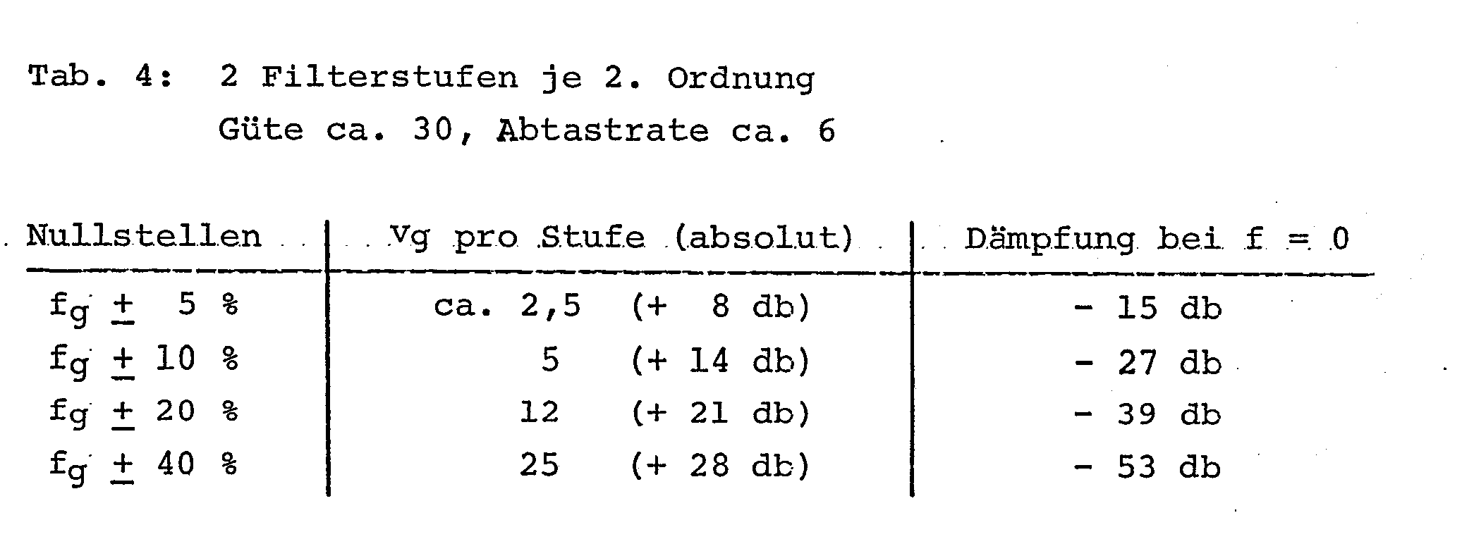
Verwendet man ein Rechenwerk mit 8-Bit-Dynamik, d.h. entsprechend 48 db und rechnet man mit Nutzsignalen von + 1 bis + 16 Einheiten Eingangsdynamik, entsprechend 30 db, so wird ersichtlich, dass die Nullstellen innerhalb eines Bereiches f + 20 % liegen müssen. v + Dynamik des Eingangssignals: 21 db + 30 db = 51 db. Anderseits sollte man im Sperrbereich des Filters eine relative Dämpfung (bezogen auf den Durchlassbereich)von ca. -30 db erreichen. Damit ergibt sich gemäss Beispiel in Tabelle 4 ein Mindestabstand der Nullstellen von f + 10 % für eine Dämpfung von - 27 db im Weitabbereich (z.B. f = o). Die fehlenden - 3 db können durch das ohnehin erforderliche analoge Vorfilter erzeugt werden.If you use an arithmetic unit with 8-bit dynamics, i.e. corresponding to 48 db and if one calculates with useful signals from + 1 to + 16 units input dynamics, corresponding to 30 db, it can be seen that the zeros must lie within a range f + 20%. v + dynamics of the input signal: 21 db + 30 db = 51 db. On the other hand, a relative attenuation (based on the pass band) of approx. -30 db should be achieved in the filter's stop band. According to the example in Table 4, this results in a minimum distance between the zeros of f + 10% for an attenuation of - 27 db in the wide range (e.g. f = o). The missing - 3 db can be generated by the already required analog pre-filter.
Damit ergeben sich in der Praxis optimale Lagen der Nullstellen zwischen f = f + 20 % und f = fg + 10 %. Dies gilt im Falle einer Abtastrate von 6 und einem Gütefaktor Q von etwa 30.In practice, this results in optimal zero positions between f = f + 20% and f = f g + 10%. This applies in the case of a sampling rate of 6 and a quality factor Q of approximately 30.
Ein beispielsweise für einen Rundsteuerempfänger geeignetes Digitalfilter gemäss der Erfindung hat beispielsweise folgende in Tabelle 5 dargestellte charakteristische Werte.

Das Verhältnis der Störfrequenzen zur Nutzfrequenz beträgt dabei 150/167 und 184/167, was den Faktoren 0,9 und 1,1 entspricht. Diese Verhältnisse sind insofern günstig, weil die Hauptstörfrequenzen gerade bei f + 10 % liegen. Da man die so eingeführten Nullstellen im Bereich von etwa f + 10 bis f + 20 % frei wählen g - g - kann, erweist es sich als besonders günstig, diese genau auf die hauptsächlichen Störfrequenzen zu legen, was zur Folge hat, dass das Filter wesentlich unempfindlicher wird, gerade gegen diese hauptsächlichen Störfrequenzen. Man erreicht durch diese Massnahme also zusätzlich noch eine markante technische Verbesserung des Filters.The ratio of the interference frequencies to the useful frequency is 150/167 and 184/167, which corresponds to the factors 0.9 and 1.1. These conditions are favorable because the main interference frequencies are just f + 10%. Since the zeros introduced in this way can be freely selected in the range from about f + 10 to f + 20% g - g - , it proves to be particularly advantageous to place them exactly on the main interference frequencies, which means that the filter becomes much less sensitive, especially to these main interference frequencies. This measure also leads to a significant technical improvement of the filter.
In der Praxis kann ein digitales Filter für Fernsteuerempfänger mit Nullstellen in der Uebertragungsfunktion wie folgt gebaut werden:
- 1. Es wird ein geeignetes Rechenwerk genommen, das die erforderliche Mindestbitzahl von z.B. 8 Bit aufweist. Vorzugsweise kann ein Microcomputer verwendet werden. Damit das vorgefilterte analoge Signal dem Rechenwerk direkt zugeführt werden kann, ist es sinnvoll einen "One Chip Microcomputer" mit eingebauten Analog-Digital Wandler einzusetzen. (z.B. MC 6805R2 von Motorola Semiconductor Products Inc., 3501 Bluestein Blvd. Austin, Texas 78721)
- 2. Es wird eine geeignete Filterstruktur gewählt. Vorzugsweise werden Filterstufen zweiter Ordnung kaskadiert. (Gemäss Fig.7) Für die einzelne Stufe wird ebenfalls eine geeignete Struktur gewählt. (z.B. gemäss Fig. 2)
- 3. Für jede Filterstufe werden nun die Filterkoeffizienten berechnet. Entsprechende Methoden, wie die Koeffizienten eines gegebenen analogen Filters, in die korrespondierenden Koeffizienten des digitalen Filter transformiert werden können, sind bekannt. (z.B. die bereits erwähnte bilineare Transformation) Zudem könnten auch Methoden angewandt werden, um selektive Stufen zweiter Ordnung, gegebener Güte Q, direkt als digitales Filter zu entwerfen. Wesentlich ist nun, dass für jene Filterkoeffizienten, welche die Lage der-Nullstellen bestimmen, diejenigen Werte eingesetzt werden, welche Nullstellen (maximale Dämpfung) im frequenzabhängigen Uebertragungsverhalten derart erzeugen, dass alle die in der Beschreibung angegebenen Erfordernisse an die Filterstufe, erfüllt werden. (Genügende Selektivität und akzeptable Resonanzfrequenzverstärkung.) Diese Filterkoeffizienten gemäss Fig. 2 berechnen sich wie folgt:


- 1. A suitable arithmetic unit is used which has the required minimum number of bits, for example 8 bits. A microcomputer can preferably be used. So that the pre-filtered analog signal can be fed directly to the arithmetic unit, it makes sense to use a "one-chip microcomputer" with an integrated analog-digital converter. (e.g. MC 6805R2 from Motorola Semiconductor Products Inc., 3501 Bluestein Blvd. Austin, Texas 78721)
- 2. A suitable filter structure is selected. Second-order filter stages are preferably cascaded. (According to Fig. 7) A suitable structure is also selected for the individual stage. (e.g. according to Fig. 2)
- 3. The filter coefficients are now calculated for each filter stage. Appropriate methods, such as the coefficients of a given analog filter, can be transformed into the corresponding coefficients of the digital filter are known. (eg the already mentioned bilinear transformation) In addition, methods could be used to design selective second-order stages, given quality Q, directly as a digital filter. It is essential that those filter coefficients that determine the position of the zeros are used for those values that generate zeros (maximum attenuation) in the frequency-dependent transmission behavior in such a way that all the filter stage requirements specified in the description are met. (Sufficient selectivity and acceptable resonance frequency gain.) These filter coefficients according to FIG. 2 are calculated as follows:
Damit ist ein geeignetes digitales Filter für Fernsteuerempfänger grundsätzlich entworfen. In weiteren Schritten muss es nur noch nach den bekannten Regeln der Kunst optimiert werden. (Skalierung, Limitierung der Wortlänge der Koeffizienten z.B.) Dies geschieht nach den Anweisungen in den erwähnten Literaturstellen.A suitable digital filter for remote control receivers is therefore basically designed. In further steps, it only has to can still be optimized according to the known rules of art. (Scaling, limiting the word length of the coefficients, for example) This is done according to the instructions in the references mentioned.
4. Das digitale Filter wird dann nach den Anleitungen der Rechenwerkhersteller ins Rechenwerk hineinprogrammiert und in allenfalls auch vorhandene andere Programme, die vorzugsweise zum Auswerten des Filterausganges dienen, eingebettet.4. The digital filter is then programmed into the arithmetic unit according to the instructions of the arithmetic unit manufacturer and embedded in any other programs that may be used, which are preferably used to evaluate the filter output.
Claims (6)
Priority Applications (1)
| Application Number | Priority Date | Filing Date | Title |
|---|---|---|---|
| AT83105834T ATE29937T1 (en) | 1982-10-01 | 1983-06-14 | DIGITAL FILTER FOR REMOTE CONTROL RECEIVERS, ESPECIALLY FOR RIPPLE CONTROL RECEIVERS. |
Applications Claiming Priority (2)
| Application Number | Priority Date | Filing Date | Title |
|---|---|---|---|
| CH5804/82A CH662224A5 (en) | 1982-10-01 | 1982-10-01 | DIGITAL FILTER FOR REMOTE CONTROL RECEIVERS, ESPECIALLY FOR RADIO CONTROL RECEIVERS. |
| CH5804/82 | 1982-10-01 |
Publications (3)
| Publication Number | Publication Date |
|---|---|
| EP0105087A2 true EP0105087A2 (en) | 1984-04-11 |
| EP0105087A3 EP0105087A3 (en) | 1985-08-21 |
| EP0105087B1 EP0105087B1 (en) | 1987-09-23 |
Family
ID=4299578
Family Applications (1)
| Application Number | Title | Priority Date | Filing Date |
|---|---|---|---|
| EP83105834A Expired EP0105087B1 (en) | 1982-10-01 | 1983-06-14 | Digital filter for a remote control receiver |
Country Status (8)
| Country | Link |
|---|---|
| US (1) | US4653016A (en) |
| EP (1) | EP0105087B1 (en) |
| AT (1) | ATE29937T1 (en) |
| AU (1) | AU556035B2 (en) |
| CH (1) | CH662224A5 (en) |
| DE (1) | DE3373855D1 (en) |
| GB (1) | GB2128437B (en) |
| NZ (1) | NZ205833A (en) |
Cited By (4)
| Publication number | Priority date | Publication date | Assignee | Title |
|---|---|---|---|---|
| FR2550669A1 (en) * | 1983-08-11 | 1985-02-15 | Landis & Gyr Ag | Pass-band acoustic frequency filter |
| FR2573589A1 (en) * | 1984-11-22 | 1986-05-23 | Zellweger Uster Ag | Method and device for demodulating high-frequency modulated signals by way of digital filters and digital demodulators, and the use of the method in a remotely-controlled receiver. |
| DE3528046A1 (en) * | 1985-08-05 | 1987-02-05 | Bbc Brown Boveri & Cie | RADIO CONTROL RECEIVER |
| EP0509246A2 (en) * | 1991-03-15 | 1992-10-21 | Siemens Aktiengesellschaft | Ripple control receiver |
Families Citing this family (6)
| Publication number | Priority date | Publication date | Assignee | Title |
|---|---|---|---|---|
| FR2564660B1 (en) * | 1984-05-21 | 1994-06-10 | Enertec | RESONANT DIGITAL FILTER |
| US4803647A (en) * | 1986-05-30 | 1989-02-07 | Rca Licensing Corporation | Sampled data audio tone control apparatus |
| JPS63311402A (en) * | 1987-06-12 | 1988-12-20 | Fanuc Ltd | Plc device |
| CN1096050C (en) * | 1993-10-28 | 2002-12-11 | 皇家菲利浦电子有限公司 | Remote control system, lighting system and filter |
| US6754626B2 (en) * | 2001-03-01 | 2004-06-22 | International Business Machines Corporation | Creating a hierarchical tree of language models for a dialog system based on prompt and dialog context |
| US20030130751A1 (en) * | 2002-01-09 | 2003-07-10 | Freesystems Pte.,Ltd. | New filter bank for graphics equalizer implementation |
Citations (4)
| Publication number | Priority date | Publication date | Assignee | Title |
|---|---|---|---|---|
| CH559983A5 (en) * | 1972-12-28 | 1975-03-14 | Zellweger Uster Ag | |
| DE2708074A1 (en) * | 1977-02-22 | 1978-08-24 | Heliowatt Werke | ELECTRONIC ROTARY CONTROL RECEIVER |
| CH607467A5 (en) * | 1975-12-03 | 1978-12-29 | Zellweger Uster Ag | |
| DE3034584A1 (en) * | 1979-09-14 | 1981-03-19 | Victor Company Of Japan, Ltd., Yokohama, Kanagawa | DIGITAL FILTER |
Family Cites Families (4)
| Publication number | Priority date | Publication date | Assignee | Title |
|---|---|---|---|---|
| US4060735A (en) * | 1976-07-12 | 1977-11-29 | Johnson Controls, Inc. | Control system employing a programmable multiple channel controller for transmitting control signals over electrical power lines |
| US4317092A (en) * | 1980-06-30 | 1982-02-23 | Hewlett-Packard Company | Recursive low pass digital filter |
| JPS57142022A (en) * | 1981-02-26 | 1982-09-02 | Casio Comput Co Ltd | Resonance characteristic controlling system in digital filter |
| US4467440A (en) * | 1980-07-09 | 1984-08-21 | Casio Computer Co., Ltd. | Digital filter apparatus with resonance characteristics |
-
1982
- 1982-10-01 CH CH5804/82A patent/CH662224A5/en not_active IP Right Cessation
-
1983
- 1983-06-14 AT AT83105834T patent/ATE29937T1/en not_active IP Right Cessation
- 1983-06-14 DE DE8383105834T patent/DE3373855D1/en not_active Expired
- 1983-06-14 EP EP83105834A patent/EP0105087B1/en not_active Expired
- 1983-09-16 GB GB08324907A patent/GB2128437B/en not_active Expired
- 1983-09-23 US US06/535,255 patent/US4653016A/en not_active Expired - Fee Related
- 1983-09-30 AU AU19830/83A patent/AU556035B2/en not_active Ceased
- 1983-09-30 NZ NZ205833A patent/NZ205833A/en unknown
Patent Citations (4)
| Publication number | Priority date | Publication date | Assignee | Title |
|---|---|---|---|---|
| CH559983A5 (en) * | 1972-12-28 | 1975-03-14 | Zellweger Uster Ag | |
| CH607467A5 (en) * | 1975-12-03 | 1978-12-29 | Zellweger Uster Ag | |
| DE2708074A1 (en) * | 1977-02-22 | 1978-08-24 | Heliowatt Werke | ELECTRONIC ROTARY CONTROL RECEIVER |
| DE3034584A1 (en) * | 1979-09-14 | 1981-03-19 | Victor Company Of Japan, Ltd., Yokohama, Kanagawa | DIGITAL FILTER |
Non-Patent Citations (1)
| Title |
|---|
| L. RABINER u.a.: "Theory and application of digital signal processing", 1975, Seiten 40-50, Prentice-Hall Inc., Englewood Cliffs, US. * |
Cited By (10)
| Publication number | Priority date | Publication date | Assignee | Title |
|---|---|---|---|---|
| FR2550669A1 (en) * | 1983-08-11 | 1985-02-15 | Landis & Gyr Ag | Pass-band acoustic frequency filter |
| FR2573589A1 (en) * | 1984-11-22 | 1986-05-23 | Zellweger Uster Ag | Method and device for demodulating high-frequency modulated signals by way of digital filters and digital demodulators, and the use of the method in a remotely-controlled receiver. |
| AT396724B (en) * | 1984-11-22 | 1993-11-25 | Zellweger Uster Ag | METHOD AND DEVICE FOR DEMODULATING HIGH FREQUENCY MODULATED SIGNALS BY MEANS OF DIGITAL FILTERS AND DIGITAL DEMODULATORS, AND USE OF THE METHOD IN A REMOTE CONTROL RECEIVER |
| DE3528046A1 (en) * | 1985-08-05 | 1987-02-05 | Bbc Brown Boveri & Cie | RADIO CONTROL RECEIVER |
| JPS6234424A (en) * | 1985-08-05 | 1987-02-14 | ブラウン・ボバリ・ウント・シ−・アクチエンゲゼルシヤフト | Centralized remote controlled receiver |
| EP0212307A2 (en) * | 1985-08-05 | 1987-03-04 | Asea Brown Boveri Aktiengesellschaft | Ripple control receiver |
| EP0212307A3 (en) * | 1985-08-05 | 1988-08-31 | Brown, Boveri & Cie Aktiengesellschaft | Ripple control receiver |
| EP0509246A2 (en) * | 1991-03-15 | 1992-10-21 | Siemens Aktiengesellschaft | Ripple control receiver |
| EP0509246A3 (en) * | 1991-03-15 | 1993-03-03 | Siemens Aktiengesellschaft | Ripple control receiver |
| AT396042B (en) * | 1991-03-15 | 1993-05-25 | Uher Ag | Ripple control receiver |
Also Published As
| Publication number | Publication date |
|---|---|
| NZ205833A (en) | 1987-11-27 |
| DE3373855D1 (en) | 1987-10-29 |
| AU556035B2 (en) | 1986-10-16 |
| EP0105087A3 (en) | 1985-08-21 |
| ATE29937T1 (en) | 1987-10-15 |
| CH662224A5 (en) | 1987-09-15 |
| GB2128437B (en) | 1986-03-05 |
| EP0105087B1 (en) | 1987-09-23 |
| AU1983083A (en) | 1984-04-05 |
| GB8324907D0 (en) | 1983-10-19 |
| GB2128437A (en) | 1984-04-26 |
| US4653016A (en) | 1987-03-24 |
Similar Documents
| Publication | Publication Date | Title |
|---|---|---|
| EP0212307B1 (en) | Ripple control receiver | |
| EP0052847B1 (en) | Method and circuit for converting the sampling frequency of a series of samples avoiding conversion into a continuous signal | |
| DE3541031A1 (en) | Method and device for demodulating RF-modulated signals by means of digital filters and digital demodulators, and use of the method in a remote-control receiver | |
| EP0105087B1 (en) | Digital filter for a remote control receiver | |
| DE2917285A1 (en) | DIGITAL SPECTRAL ANALYZER | |
| EP0610990B1 (en) | Digital phase-locked loop | |
| WO1987005411A1 (en) | Adaptive regulating system with high precision and low positioning-energy consumption | |
| EP1458216A2 (en) | Device and method for adaption of microphones in a hearing aid | |
| DE10131224C1 (en) | Electrical filter with blocking properties for predetermined frequency has finite, infinite impulse response filters essentially tuned to blocking and low pass properties respectively | |
| DE4000131C1 (en) | ||
| DE4109211A1 (en) | CIRCUIT ARRANGEMENT FOR INFLUENCING THE DIGITAL AUDIO SIGNAL | |
| DE2008560C3 (en) | Message transmission system using pulse code modulation and pulse compression on the receiver side | |
| DE2419022A1 (en) | METHOD AND DEVICE FOR PROCESSING ANALOGUE DATA IN SCALES | |
| DE1912674A1 (en) | Digital phase equalizer | |
| DE3504383C2 (en) | ||
| DE3439977A1 (en) | DIGITAL FILTER WITH ANY ADJUSTABLE FREQUENCY GEAR | |
| DE672801C (en) | Electrical wave filter with several blocking and transmission ranges, whose damping and / or wave resistance function is derived from the damping or wave resistance function of a wave filter with only one transmission range | |
| EP0903899A2 (en) | Method and apparatus for evaluating Multifrequency tone signals using an adaptive wave digital notch filter | |
| AT411001B (en) | METHOD AND CIRCUIT FOR FILTERING SIGNALS | |
| DE2820905C2 (en) | Electronic filter | |
| DE1908719C (en) | Crystal comb filter | |
| DE3406833C2 (en) | ||
| DE3418011A1 (en) | Bandpass filter for receiving a sound signal transmitted via an electrical power supply network | |
| DE2618060C2 (en) | ||
| DE19722873A1 (en) | Sampling rate converter e.g. for radio transmission of voice signals |
Legal Events
| Date | Code | Title | Description |
|---|---|---|---|
| PUAI | Public reference made under article 153(3) epc to a published international application that has entered the european phase |
Free format text: ORIGINAL CODE: 0009012 |
|
| 17P | Request for examination filed |
Effective date: 19830614 |
|
| AK | Designated contracting states |
Designated state(s): AT BE DE FR |
|
| EL | Fr: translation of claims filed | ||
| PUAL | Search report despatched |
Free format text: ORIGINAL CODE: 0009013 |
|
| AK | Designated contracting states |
Designated state(s): AT BE DE FR |
|
| 17Q | First examination report despatched |
Effective date: 19860627 |
|
| GRAA | (expected) grant |
Free format text: ORIGINAL CODE: 0009210 |
|
| AK | Designated contracting states |
Kind code of ref document: B1 Designated state(s): AT BE DE FR |
|
| REF | Corresponds to: |
Ref document number: 29937 Country of ref document: AT Date of ref document: 19871015 Kind code of ref document: T |
|
| REF | Corresponds to: |
Ref document number: 3373855 Country of ref document: DE Date of ref document: 19871029 |
|
| ET | Fr: translation filed | ||
| PLBE | No opposition filed within time limit |
Free format text: ORIGINAL CODE: 0009261 |
|
| STAA | Information on the status of an ep patent application or granted ep patent |
Free format text: STATUS: NO OPPOSITION FILED WITHIN TIME LIMIT |
|
| 26N | No opposition filed | ||
| PGFP | Annual fee paid to national office [announced via postgrant information from national office to epo] |
Ref country code: DE Payment date: 19940608 Year of fee payment: 12 |
|
| PGFP | Annual fee paid to national office [announced via postgrant information from national office to epo] |
Ref country code: FR Payment date: 19940609 Year of fee payment: 12 |
|
| PGFP | Annual fee paid to national office [announced via postgrant information from national office to epo] |
Ref country code: AT Payment date: 19940614 Year of fee payment: 12 |
|
| PGFP | Annual fee paid to national office [announced via postgrant information from national office to epo] |
Ref country code: BE Payment date: 19940808 Year of fee payment: 12 |
|
| PG25 | Lapsed in a contracting state [announced via postgrant information from national office to epo] |
Ref country code: AT Effective date: 19950614 |
|
| PG25 | Lapsed in a contracting state [announced via postgrant information from national office to epo] |
Ref country code: BE Effective date: 19950630 |
|
| BERE | Be: lapsed |
Owner name: ZELLWEGER USTER A.G. Effective date: 19950630 |
|
| PG25 | Lapsed in a contracting state [announced via postgrant information from national office to epo] |
Ref country code: FR Effective date: 19960229 |
|
| PG25 | Lapsed in a contracting state [announced via postgrant information from national office to epo] |
Ref country code: DE Effective date: 19960301 |
|
| REG | Reference to a national code |
Ref country code: FR Ref legal event code: ST |