EP0104792A1 - Method of making an ignition coil core - Google Patents
Method of making an ignition coil core Download PDFInfo
- Publication number
- EP0104792A1 EP0104792A1 EP83305023A EP83305023A EP0104792A1 EP 0104792 A1 EP0104792 A1 EP 0104792A1 EP 83305023 A EP83305023 A EP 83305023A EP 83305023 A EP83305023 A EP 83305023A EP 0104792 A1 EP0104792 A1 EP 0104792A1
- Authority
- EP
- European Patent Office
- Prior art keywords
- laminated member
- center leg
- outer legs
- laminated
- oblique surfaces
- Prior art date
- Legal status (The legal status is an assumption and is not a legal conclusion. Google has not performed a legal analysis and makes no representation as to the accuracy of the status listed.)
- Granted
Links
- 238000004519 manufacturing process Methods 0.000 title claims description 6
- 238000000034 method Methods 0.000 claims description 7
- 238000012544 monitoring process Methods 0.000 claims description 3
- 238000005452 bending Methods 0.000 claims 2
- 230000008569 process Effects 0.000 description 5
- 238000004804 winding Methods 0.000 description 5
- 238000003475 lamination Methods 0.000 description 2
- 239000000463 material Substances 0.000 description 2
- 230000009467 reduction Effects 0.000 description 2
- 238000003466 welding Methods 0.000 description 2
- 229910000976 Electrical steel Inorganic materials 0.000 description 1
- 230000008859 change Effects 0.000 description 1
- 238000002485 combustion reaction Methods 0.000 description 1
- 230000000694 effects Effects 0.000 description 1
- 230000004907 flux Effects 0.000 description 1
- 239000011261 inert gas Substances 0.000 description 1
- 239000012212 insulator Substances 0.000 description 1
- 230000007246 mechanism Effects 0.000 description 1
- 239000000203 mixture Substances 0.000 description 1
- 230000000717 retained effect Effects 0.000 description 1
- WFKWXMTUELFFGS-UHFFFAOYSA-N tungsten Chemical compound [W] WFKWXMTUELFFGS-UHFFFAOYSA-N 0.000 description 1
- 229910052721 tungsten Inorganic materials 0.000 description 1
- 239000010937 tungsten Substances 0.000 description 1
Images
Classifications
-
- H—ELECTRICITY
- H01—ELECTRIC ELEMENTS
- H01F—MAGNETS; INDUCTANCES; TRANSFORMERS; SELECTION OF MATERIALS FOR THEIR MAGNETIC PROPERTIES
- H01F27/00—Details of transformers or inductances, in general
- H01F27/24—Magnetic cores
- H01F27/245—Magnetic cores made from sheets, e.g. grain-oriented
-
- H—ELECTRICITY
- H01—ELECTRIC ELEMENTS
- H01F—MAGNETS; INDUCTANCES; TRANSFORMERS; SELECTION OF MATERIALS FOR THEIR MAGNETIC PROPERTIES
- H01F3/00—Cores, Yokes, or armatures
- H01F3/10—Composite arrangements of magnetic circuits
- H01F3/14—Constrictions; Gaps, e.g. air-gaps
-
- H—ELECTRICITY
- H01—ELECTRIC ELEMENTS
- H01F—MAGNETS; INDUCTANCES; TRANSFORMERS; SELECTION OF MATERIALS FOR THEIR MAGNETIC PROPERTIES
- H01F41/00—Apparatus or processes specially adapted for manufacturing or assembling magnets, inductances or transformers; Apparatus or processes specially adapted for manufacturing materials characterised by their magnetic properties
- H01F41/02—Apparatus or processes specially adapted for manufacturing or assembling magnets, inductances or transformers; Apparatus or processes specially adapted for manufacturing materials characterised by their magnetic properties for manufacturing cores, coils, or magnets
- H01F41/0206—Manufacturing of magnetic cores by mechanical means
- H01F41/0233—Manufacturing of magnetic circuits made from sheets
-
- Y—GENERAL TAGGING OF NEW TECHNOLOGICAL DEVELOPMENTS; GENERAL TAGGING OF CROSS-SECTIONAL TECHNOLOGIES SPANNING OVER SEVERAL SECTIONS OF THE IPC; TECHNICAL SUBJECTS COVERED BY FORMER USPC CROSS-REFERENCE ART COLLECTIONS [XRACs] AND DIGESTS
- Y10—TECHNICAL SUBJECTS COVERED BY FORMER USPC
- Y10T—TECHNICAL SUBJECTS COVERED BY FORMER US CLASSIFICATION
- Y10T29/00—Metal working
- Y10T29/49—Method of mechanical manufacture
- Y10T29/49002—Electrical device making
- Y10T29/49004—Electrical device making including measuring or testing of device or component part
-
- Y—GENERAL TAGGING OF NEW TECHNOLOGICAL DEVELOPMENTS; GENERAL TAGGING OF CROSS-SECTIONAL TECHNOLOGIES SPANNING OVER SEVERAL SECTIONS OF THE IPC; TECHNICAL SUBJECTS COVERED BY FORMER USPC CROSS-REFERENCE ART COLLECTIONS [XRACs] AND DIGESTS
- Y10—TECHNICAL SUBJECTS COVERED BY FORMER USPC
- Y10T—TECHNICAL SUBJECTS COVERED BY FORMER US CLASSIFICATION
- Y10T29/00—Metal working
- Y10T29/49—Method of mechanical manufacture
- Y10T29/49002—Electrical device making
- Y10T29/4902—Electromagnet, transformer or inductor
- Y10T29/49073—Electromagnet, transformer or inductor by assembling coil and core
-
- Y—GENERAL TAGGING OF NEW TECHNOLOGICAL DEVELOPMENTS; GENERAL TAGGING OF CROSS-SECTIONAL TECHNOLOGIES SPANNING OVER SEVERAL SECTIONS OF THE IPC; TECHNICAL SUBJECTS COVERED BY FORMER USPC CROSS-REFERENCE ART COLLECTIONS [XRACs] AND DIGESTS
- Y10—TECHNICAL SUBJECTS COVERED BY FORMER USPC
- Y10T—TECHNICAL SUBJECTS COVERED BY FORMER US CLASSIFICATION
- Y10T29/00—Metal working
- Y10T29/49—Method of mechanical manufacture
- Y10T29/49002—Electrical device making
- Y10T29/4902—Electromagnet, transformer or inductor
- Y10T29/49075—Electromagnet, transformer or inductor including permanent magnet or core
- Y10T29/49078—Laminated
Definitions
- This invention relates to a laminated core of an ignition coil for use in the spark ignition system of an internal combustion engine.
- a preferred form for such a core is a stack of laminations in a generally rectangular ring having a central leg extending from one side of said ring across the central opening thereof to the other side and also including an air gap.
- the primary and secondary windings of the ignition coil are wound on the central leg with the remainder of the coil providing a return flux path to complete the magnetic circuit.
- Such a core is generally manufactured by stacking laminations into two parts: the first part in the shape of an E with central and outer legs and the second part in-the shape of an E with shorter legs or in the shape of a bar capable of spanning or just fitting within the outer legs of the first piece.
- the manufacture of the core in two pieces simplifies the assembly process by allowing prewound and formed coils to be dropped over the center leg before the two pieces are joined together.
- it still does not completely solve the problem of controlling the size of the air gap in the assembled ignition coil to produce a coil with predetermined magnetic and electrical performance. In normal assembly, it is found that a certain proportion of ignition coils do not have performance properties within acceptable limits.
- the first laminated member has an E shape with equal length outer legs having oblique surfaces on the inner free end thereof and a shorter center leg.
- the second laminated member has a bar shape with oblique faces at each end thereof corresponding to the oblique faces of the outer legs of the first laminated member when oriented perpendicularly to the center leg thereof.
- the oblique faces of the second laminated member form angles with respect to the center leg of the first laminated member which are greater before final assembly and at least as great after final assembly as the corresponding angles of the oblique faces of the first laminated member.
- the second laminated member In assembly, the second laminated member is advanced toward the center leg of the first laminated member with the oblique faces cooperating to bend the outer legs of the first laminated member slightly outward away from the center leg to generate a spring-like restoring force to stabilize the relative positions of the members and the properties of the core are monitored by means of the ignition coil; and advancement of the second laminated member is halted and the two members welded together when such properties are within the desired limits.
- the difference in the angles of the oblique faces of the two laminated members before assembly are sufficiently great that, in the assembled core, the angles formed by the oblique faces of the second laminated member are still at least as great as those of the first laminated member.
- first and second laminated members 10 and 30 may be made, for example, of multiple laminated, layers of 0.254mm (0.010 inch) thick M-3 grain oriented, electrical steel with a C-5 core plate, although similar materials are acceptable.
- First laminated member 10 has an E shape with a base 11, a central leg 12 projecting perpendicularly from the center of base 11, and a pair of outer legs 13-and 14 extending from the opposite ends of base 11 in the same direction of center leg 12 and parallel thereto with first laminated member 10 in the unassembled state.
- Center leg 12 is shorter than the equal length outer legs 13 and 14 and has a flat end surface 15 which is perpendicular to an imaginary axis running straight through the center of the center leg 12 perpendicular to base 11.
- Each of the outer legs 13 and 14 is provided, on its inner free end facing center leg 12, with an oblique surface, which oblique surfaces are number 16 and 17 for legs 13 and 14, respectively, in Figure 1.
- These oblique surfaces 16 and 17 form identical angles of 29°, when first laminated member 10 is in its unassembled state, with the planes of the inner sides 18 and 19 of center leg 12 which are themselves parallel with the imaginary axis through the center of center leg 12.
- Second laminated member 30 is in the shape of a bar and is shown in Figure 1 as being oriented perpendicularly to the imaginary axis through the center of center leg 12 of first laminated member 10.
- Second laminated member 30 has a lower surface 31 which, in the.previously described orientation, is parallel with end surface 15 of center leg 12 of first laminated member 10.
- Second laminated member 30 further has, at the ends thereof, oblique surfaces 32 and 33 adjacent the oblique surfaces 16 and 17, respectively, of first laminated member 10.
- the length of second laminated member 30 is greater at the upper surface 34 thereof than the distance between the upper edges 16' and 17' of oblique surfaces 16 and 17; but its length at the lower surface 31 is less than the distance between edges 16' and 17'.
- Oblique surfaces 32 and 33 form identical angles of 30° with the planes of surfaces 18 and 19. of center leg 12 of first laminated member 10. Therefore, if second laminated member 30 is advanced toward the center leg 12 of first laminated member 10 with its perpendicular orientation retained, edges 16' and 17' of the outer legs 13 and 14, respectively, of first laminated member 10 will eventually engage oblique surfaces 32 and 33 of second laminated member 30. Additional movement of the second laminated member 30 toward the center leg 12 of first laminated member 10 can only be accomplished against the spring force of the outer lees 13 and 14 of first laminated member 10 as they are bent outward by the oblique surfaces 32 and 33 of the advancing second laminated member 30.
- the main air gap is that between surface 15 of center leg 12 of first laminated member 10 and the lower surface 31 of second laminated member 30.
- the dimensions of the first and second laminated members 10 and 30 are such that the total air gap at this point is no greater than the desired air gap for the assembled core.
- first laminated member 10 With appropriate insulators and other parts as shown in Figure 2.
- This coil is shown only in representative form in Figure 2, since it actually comprises a pair of coil windings forming a transformer with an annularly large secondary coil of many turns surrounding an annularly thin primary coil of a much smaller number of turns as is well known in the art of ignition coils.
- the precise structure and composition of the coil or transformer 25 is irrelevant to this invention as long as it is in place around center leg 12.
- the inductance of the core may be measured by the application of current to one of the windings. Since the inductance varies with the total effective air gap, this total effective air gap can be effectively monitored during the final assembly process.
- second laminated member 30 is oriented perpendicularly to the center leg 12 of first laminated member 10 as shown in Figure 1 as described above and advanced as previously described until the monitored total effective air gap reaches the desired value.
- the first laminated member 10 may be held stationary in a proper fixture while the second laminated member 30 is advanced against the increasina spring force generated by the outwardly bent outer legs 13 and 14 of first laminated member 10. This increasing spring force contributes to the smoothness of operation of the assembling fixture, since it takes up any possible free play or slack in the mechanism and helps stabilize the members.
- the second laminated member When the desired total effective air cap is obtained, the second laminated member may be welded across the full width thereof.at each end to the adjacent outer leg of the first laminated member, as shown at reference numeral 28, with a tungsten inert gas welding electrode.
- a tungsten inert gas welding electrode As a practical matter, to allow for some springback in the completed and welded assembly due to the spring force of outer legs 13 and 14 of first laminated member 10, it may be necessary to advance the second laminated member 30 a predetermined distance past the point of desired total effective air cap before welding takes place so that the desired total effective air gap will be obtained by the finished assembly after springback. If this is the case, other statements in this specification and the following claims should be modified where appropriate in accordance therewith in the manner known to those skilled in the art.
- the assembly of the core while varying the air gap and monitoring the inductance of the core and winding permits the magnetic and electrical characteristics of the ignition coil to be determined during this final assembly and thus reduces scrappage, regardless of dimensional and material variations in the various parts of the assembly.
- the oblique surfaces of the laminated members facilitate the easy fitting together of the parts and enable the spring force of the outer legs of the E shaped laminated member to help stabilize the members and ensure good physical engagement of the members for minimal secondary air gaps and a strong, stable final assembly.
Landscapes
- Engineering & Computer Science (AREA)
- Power Engineering (AREA)
- Manufacturing & Machinery (AREA)
- Chemical & Material Sciences (AREA)
- Composite Materials (AREA)
- Ignition Installations For Internal Combustion Engines (AREA)
- Manufacturing Cores, Coils, And Magnets (AREA)
Abstract
Description
- This invention relates to a laminated core of an ignition coil for use in the spark ignition system of an internal combustion engine. A preferred form for such a core is a stack of laminations in a generally rectangular ring having a central leg extending from one side of said ring across the central opening thereof to the other side and also including an air gap. The primary and secondary windings of the ignition coil are wound on the central leg with the remainder of the coil providing a return flux path to complete the magnetic circuit.
- Such a core is generally manufactured by stacking laminations into two parts: the first part in the shape of an E with central and outer legs and the second part in-the shape of an E with shorter legs or in the shape of a bar capable of spanning or just fitting within the outer legs of the first piece. The manufacture of the core in two pieces simplifies the assembly process by allowing prewound and formed coils to be dropped over the center leg before the two pieces are joined together. However, it still does not completely solve the problem of controlling the size of the air gap in the assembled ignition coil to produce a coil with predetermined magnetic and electrical performance. In normal assembly, it is found that a certain proportion of ignition coils do not have performance properties within acceptable limits. It is desirable, therefore, to be able to adjust the air cap during the final assembly of the core while the performance properties may be measured by means of the ignition coil windings. Not only is the final air cap controllable at this time, but the adjustment of this air gap while measuring a variable such as inductance automatically corrects for variations in other variables affecting the magnetic properties of the ignition coil.
- In the case of two E shaped members which are clamped or welded together during final assembly the total effective air gap is not generally adjustable but is determined by the precise physical characteristics of the members, with air gap contributions from the joints at the outer legs to imperfections in the surfaces caused by variations in the individual lamina. The same is true of a bar shaped piece placed against the end of an E shaped piece and contacting the ends of the outer legs. If a bar shaped piece is made to insert between the ends of the outer legs of an E shaped piece some adjustability is possible. However, if a very tight fit is obtained, the pieces are difficult to assemble and adjust, whereas a loose fit creates structural weakness in the assembled core and control problems due to large and possibly variable-air gaps at the ends of the bar shaped piece.
- It is an object of this invention to provide an ignition coil core and method of making the same in which the air gap of said core may be simply adjusted and permanently fixed during final assembly thereof while monitoring a parameter indicating the magnetic and electrical performance of the coil.
- It is another object of this invention to provide such a core and method of making the same providing for easy assembly and suited to automated high volume mass production.
- These and other objects are obtained in an ignition coil core having first and second laminated members. The first laminated member has an E shape with equal length outer legs having oblique surfaces on the inner free end thereof and a shorter center leg. The second laminated member has a bar shape with oblique faces at each end thereof corresponding to the oblique faces of the outer legs of the first laminated member when oriented perpendicularly to the center leg thereof. The oblique faces of the second laminated member form angles with respect to the center leg of the first laminated member which are greater before final assembly and at least as great after final assembly as the corresponding angles of the oblique faces of the first laminated member. In assembly, the second laminated member is advanced toward the center leg of the first laminated member with the oblique faces cooperating to bend the outer legs of the first laminated member slightly outward away from the center leg to generate a spring-like restoring force to stabilize the relative positions of the members and the properties of the core are monitored by means of the ignition coil; and advancement of the second laminated member is halted and the two members welded together when such properties are within the desired limits. The difference in the angles of the oblique faces of the two laminated members before assembly are sufficiently great that, in the assembled core, the angles formed by the oblique faces of the second laminated member are still at least as great as those of the first laminated member.
- Further details and advantages of this invention will be apparent from the accompanying drawings and following description of a preferred embodiment.
-
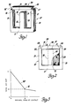
- Figure 1 is a perspective view of the two members from which the core of this invention is assembled.
- Figure 2 is a partially cut-away side view of an ignition coil including a core according to this invention.
- Figure 3 is a curve of total effective air gap versus distance from first contact as the members in Figure 1 are moved together during assembly of the core of this invention.
- Referring to Figure 1, first and second laminated
members member 10 has an E shape with a base 11, acentral leg 12 projecting perpendicularly from the center of base 11, and a pair of outer legs 13-and 14 extending from the opposite ends of base 11 in the same direction ofcenter leg 12 and parallel thereto with first laminatedmember 10 in the unassembled state.Center leg 12 is shorter than the equal lengthouter legs 13 and 14 and has aflat end surface 15 which is perpendicular to an imaginary axis running straight through the center of thecenter leg 12 perpendicular to base 11. - Each of the
outer legs 13 and 14 is provided, on its inner free end facingcenter leg 12, with an oblique surface, which oblique surfaces arenumber legs 13 and 14, respectively, in Figure 1. Theseoblique surfaces member 10 is in its unassembled state, with the planes of theinner sides center leg 12 which are themselves parallel with the imaginary axis through the center ofcenter leg 12. - Second laminated
member 30 is in the shape of a bar and is shown in Figure 1 as being oriented perpendicularly to the imaginary axis through the center ofcenter leg 12 of first laminatedmember 10. Second laminatedmember 30 has alower surface 31 which, in the.previously described orientation, is parallel withend surface 15 ofcenter leg 12 of first laminatedmember 10. Second laminatedmember 30 further has, at the ends thereof,oblique surfaces oblique surfaces member 10. The length of second laminatedmember 30 is greater at theupper surface 34 thereof than the distance between the upper edges 16' and 17' ofoblique surfaces lower surface 31 is less than the distance between edges 16' and 17'.Oblique surfaces surfaces center leg 12 of first laminatedmember 10. Therefore, if second laminatedmember 30 is advanced toward thecenter leg 12 of first laminatedmember 10 with its perpendicular orientation retained, edges 16' and 17' of theouter legs 13 and 14, respectively, of first laminatedmember 10 will eventually engageoblique surfaces member 30. Additional movement of the second laminatedmember 30 toward thecenter leg 12 of first laminatedmember 10 can only be accomplished against the spring force of theouter lees 13 and 14 of first laminatedmember 10 as they are bent outward by theoblique surfaces member 30. Since theouter lees 13 and 14 are being bent outward, the angles formed byoblique surfaces sides center leg 12 increase until, when said angles reach 30°,oblique surfaces oblique surfaces - At this point there is a minimal air gap between the ends of second laminated
member 30 and theouter legs 13 and 14 of first laminatedmember 10. The main air gap is that betweensurface 15 ofcenter leg 12 of first laminatedmember 10 and thelower surface 31 of second laminatedmember 30. The dimensions of the first and second laminatedmembers member 30 is advanced toward thecenter leg 12 of first laminatedmember 10 in the manner described above, the desired air gap will be reached at or before the point at which the air gaps between second laminatedmember 30 and theouter legs 13 and 14 of first laminatedmember 10 reach their minimum values. - Since the total effective air gap of the core is affected by all air gaps in the magnetic circuit, the effect on the total effective air gap - of the advancement of second laminated
member 30 toward thecenter leg 12 of first laminatedmember 10 can be seen in the graph of Figure 3. In this somewhat idealized graph, the total air gap is measured along the vertical axis from the origin; whereas the distance moved by second laminatedmember 30 from the first contact with the outer less 13 and 14 of first laminatedmember 10 is measured along the horizontal axis.Curve 40 represents the variation in the total effective air cap (or another variable proportional thereto), which assumes the value C at the point of first contact, as seen at the intersection ofcurve 40 with the vertical axis. As second laminatedmember 30 is advanced from this point of first contact, there is a consistent reduction of the air gaps between second laminatedmember 30 and the outer legs of first laminatedmember 10 as. veil as that between second laminatedmember 30 and thecenter leg 12 of first laminatedmember 10. This causes a consistent, smooth reduction in the total air gap until theoblique surfaces oblique surfaces member 30 and theouter legs 13 and 14 of first laminatedmember 10 reach their minimum values. This is represented in the graph by point 41, with a total effective air gap A and a distance from first contact B. Further advancement of second laminatedmember 30 toward thecenter leg 12 of first laminatedmember 10 from this point will cause an increase in the air gaps between second laminatedmember 30 and theouter legs 13 and 14 of first laminatedmember 10 to be combined with the further decrease in the air gap between the second laminatedmember 30 andcenter leg 12 of first laminatedmember 10. This results in an abrupt discontinuity incurve 40 as seen in Figure 3. To avoid this discontinuity and preserve the smooth change of the total effective air cap during the assembly process, the parts are designed with dimensions such that the desired total effective air gap is less than C and no less than A. Thus the desired total effective air cap will be attained while on the smooth continuous part ofcurve 40 up to or possibly including point 41. This simplifies the required control algorithms of the automatic control of the assembly process. - The process of assembly of the core is described below. First the assembled coil is wound or placed around the
center leg 12 of first laminatedmember 10 with appropriate insulators and other parts as shown in Figure 2. This coil is shown only in representative form in Figure 2, since it actually comprises a pair of coil windings forming a transformer with an annularly large secondary coil of many turns surrounding an annularly thin primary coil of a much smaller number of turns as is well known in the art of ignition coils. In any event, the precise structure and composition of the coil ortransformer 25 is irrelevant to this invention as long as it is in place aroundcenter leg 12. - Whatever the form of coil or
transformer 25, once it is in place the inductance of the core may be measured by the application of current to one of the windings. Since the inductance varies with the total effective air gap, this total effective air gap can be effectively monitored during the final assembly process. - While the total effective air gap is being monitored, second laminated
member 30 is oriented perpendicularly to thecenter leg 12 of first laminatedmember 10 as shown in Figure 1 as described above and advanced as previously described until the monitored total effective air gap reaches the desired value. The first laminatedmember 10 may be held stationary in a proper fixture while the second laminatedmember 30 is advanced against the increasina spring force generated by the outwardly bentouter legs 13 and 14 of first laminatedmember 10. This increasing spring force contributes to the smoothness of operation of the assembling fixture, since it takes up any possible free play or slack in the mechanism and helps stabilize the members. When the desired total effective air cap is obtained, the second laminated member may be welded across the full width thereof.at each end to the adjacent outer leg of the first laminated member, as shown atreference numeral 28, with a tungsten inert gas welding electrode. As a practical matter, to allow for some springback in the completed and welded assembly due to the spring force ofouter legs 13 and 14 of firstlaminated member 10, it may be necessary to advance the second laminated member 30 a predetermined distance past the point of desired total effective air cap before welding takes place so that the desired total effective air gap will be obtained by the finished assembly after springback. If this is the case, other statements in this specification and the following claims should be modified where appropriate in accordance therewith in the manner known to those skilled in the art. - The assembly of the core while varying the air gap and monitoring the inductance of the core and winding permits the magnetic and electrical characteristics of the ignition coil to be determined during this final assembly and thus reduces scrappage, regardless of dimensional and material variations in the various parts of the assembly. The oblique surfaces of the laminated members facilitate the easy fitting together of the parts and enable the spring force of the outer legs of the E shaped laminated member to help stabilize the members and ensure good physical engagement of the members for minimal secondary air gaps and a strong, stable final assembly. Variations from the structure and method shown and described herein will occur to these skilled in the art; therefore this invention should be limited only by the claims which follow.
Claims (2)
Applications Claiming Priority (2)
| Application Number | Priority Date | Filing Date | Title |
|---|---|---|---|
| US424465 | 1982-09-27 | ||
| US06/424,465 US4480377A (en) | 1982-09-27 | 1982-09-27 | Method of making an ignition coil core |
Publications (2)
| Publication Number | Publication Date |
|---|---|
| EP0104792A1 true EP0104792A1 (en) | 1984-04-04 |
| EP0104792B1 EP0104792B1 (en) | 1987-03-18 |
Family
ID=23682718
Family Applications (1)
| Application Number | Title | Priority Date | Filing Date |
|---|---|---|---|
| EP83305023A Expired EP0104792B1 (en) | 1982-09-27 | 1983-08-31 | Method of making an ignition coil core |
Country Status (5)
| Country | Link |
|---|---|
| US (1) | US4480377A (en) |
| EP (1) | EP0104792B1 (en) |
| JP (1) | JPS5978516A (en) |
| CA (1) | CA1192636A (en) |
| DE (1) | DE3370402D1 (en) |
Cited By (1)
| Publication number | Priority date | Publication date | Assignee | Title |
|---|---|---|---|---|
| GB2199193A (en) * | 1986-11-21 | 1988-06-29 | Nippon Denso Co | Ignition coil |
Families Citing this family (13)
| Publication number | Priority date | Publication date | Assignee | Title |
|---|---|---|---|---|
| US4706639A (en) * | 1986-12-04 | 1987-11-17 | General Motors Corporation | Integrated direct ignition module |
| US5073766A (en) * | 1990-11-16 | 1991-12-17 | Square D Company | Transformer core and method for stacking the core |
| US5218936A (en) * | 1992-11-13 | 1993-06-15 | Ford Motor Company | Ignition system including spark distribution cassette and ignition coil |
| US5469124A (en) * | 1994-06-10 | 1995-11-21 | Westinghouse Electric Corp. | Heat dissipating transformer coil |
| US6650217B1 (en) * | 1997-03-07 | 2003-11-18 | Koninklijke Philips Electronics N.V. | Low profile magnetic component with planar winding structure having reduced conductor loss |
| DE10132718A1 (en) * | 2001-07-05 | 2003-02-13 | Abb T & D Tech Ltd | Method for winding a three-phase cable transformer with coaxial cable and winding device therefor |
| US10431367B2 (en) * | 2005-09-22 | 2019-10-01 | Radial Electronics, Inc. | Method for gapping an embedded magnetic device |
| CN2924745Y (en) * | 2006-01-26 | 2007-07-18 | 杨建文 | Electronic ballast |
| EP1887586A1 (en) * | 2006-08-09 | 2008-02-13 | Magneti Marelli Holding S.p.A. | Ignition coil and assembly method thereof |
| EP1887589A1 (en) * | 2006-08-09 | 2008-02-13 | Magneti Marelli Holding S.p.A. | Ignition coil |
| US7834737B2 (en) * | 2007-09-10 | 2010-11-16 | Delphi Technologies, Inc. | Ignition apparatus having bonded steel wire central core |
| CN107533903B (en) * | 2015-05-13 | 2019-11-22 | 三菱电机株式会社 | Ignition coils |
| EP4290537A1 (en) * | 2022-06-10 | 2023-12-13 | FRONIUS INTERNATIONAL GmbH | Throttle and method for manufacturing such a throttle |
Citations (5)
| Publication number | Priority date | Publication date | Assignee | Title |
|---|---|---|---|---|
| FR1558102A (en) * | 1967-03-20 | 1969-02-21 | ||
| US3522569A (en) * | 1967-07-20 | 1970-08-04 | Gen Electric | Magnetic core and coil assembly having a gap which is fixed by a reinforced adhesive layer spanning the gap |
| DE2950727A1 (en) * | 1979-12-17 | 1981-06-25 | May & Christe Gmbh, Transformatorenwerke, 6370 Oberursel | Choke coil for fluorescent tube ballast set - has U=shaped shell core with width-height ratio of two to one, its shanks being inwardly bevelled |
| EP0042898A1 (en) * | 1980-06-30 | 1982-01-06 | S.A Clarel | Laminated magnetic circuit with air gap, and method of adjusting the air gap |
| DE3030641A1 (en) * | 1980-08-13 | 1982-04-01 | Siemens AG, 1000 Berlin und 8000 München | Miniature coil or transformer assembly - has magnetic core formed from compressed stack of laminations of specified size and shape |
Family Cites Families (6)
| Publication number | Priority date | Publication date | Assignee | Title |
|---|---|---|---|---|
| US2712084A (en) * | 1955-06-28 | Motor stator assembly | ||
| US1748993A (en) * | 1926-10-19 | 1930-03-04 | Western Electric Co | Electrical coil and method of manufacturing it |
| US1841685A (en) * | 1930-08-27 | 1932-01-19 | Joseph G Sola | Transformer |
| US2220126A (en) * | 1937-01-13 | 1940-11-05 | Hartford Nat Bank & Trust Co | Inductance coil |
| US2439277A (en) * | 1944-01-15 | 1948-04-06 | Bendix Aviat Corp | High-frequency coil |
| US3209294A (en) * | 1962-10-23 | 1965-09-28 | Westinghouse Electric Corp | Magnetic core structures |
-
1982
- 1982-09-27 US US06/424,465 patent/US4480377A/en not_active Expired - Lifetime
-
1983
- 1983-07-11 CA CA000432182A patent/CA1192636A/en not_active Expired
- 1983-08-31 EP EP83305023A patent/EP0104792B1/en not_active Expired
- 1983-08-31 DE DE8383305023T patent/DE3370402D1/en not_active Expired
- 1983-09-27 JP JP58177189A patent/JPS5978516A/en active Granted
Patent Citations (5)
| Publication number | Priority date | Publication date | Assignee | Title |
|---|---|---|---|---|
| FR1558102A (en) * | 1967-03-20 | 1969-02-21 | ||
| US3522569A (en) * | 1967-07-20 | 1970-08-04 | Gen Electric | Magnetic core and coil assembly having a gap which is fixed by a reinforced adhesive layer spanning the gap |
| DE2950727A1 (en) * | 1979-12-17 | 1981-06-25 | May & Christe Gmbh, Transformatorenwerke, 6370 Oberursel | Choke coil for fluorescent tube ballast set - has U=shaped shell core with width-height ratio of two to one, its shanks being inwardly bevelled |
| EP0042898A1 (en) * | 1980-06-30 | 1982-01-06 | S.A Clarel | Laminated magnetic circuit with air gap, and method of adjusting the air gap |
| DE3030641A1 (en) * | 1980-08-13 | 1982-04-01 | Siemens AG, 1000 Berlin und 8000 München | Miniature coil or transformer assembly - has magnetic core formed from compressed stack of laminations of specified size and shape |
Cited By (2)
| Publication number | Priority date | Publication date | Assignee | Title |
|---|---|---|---|---|
| GB2199193A (en) * | 1986-11-21 | 1988-06-29 | Nippon Denso Co | Ignition coil |
| GB2199193B (en) * | 1986-11-21 | 1991-01-09 | Nippon Denso Co | Ignition coil |
Also Published As
| Publication number | Publication date |
|---|---|
| DE3370402D1 (en) | 1987-04-23 |
| US4480377A (en) | 1984-11-06 |
| JPH0144003B2 (en) | 1989-09-25 |
| CA1192636A (en) | 1985-08-27 |
| JPS5978516A (en) | 1984-05-07 |
| EP0104792B1 (en) | 1987-03-18 |
Similar Documents
| Publication | Publication Date | Title |
|---|---|---|
| US4480377A (en) | Method of making an ignition coil core | |
| US2962679A (en) | Coaxial core inductive structures | |
| EP0412678B1 (en) | Ignition coil | |
| EP0570666B1 (en) | Variable inductance coil device | |
| EP0716436B1 (en) | Ignition coil for an internal combustion engine | |
| US20060158303A1 (en) | Snap-together choke and transformer assembly for an electric arc welder | |
| US6474322B1 (en) | Ignition device for internal combustion engine | |
| US2840889A (en) | Method of forming wound magnetic cores | |
| US4064473A (en) | Transformer with windings in helical slots of core | |
| JPH0636950A (en) | Magnetic core of ignition coil for internal combustion engine | |
| JPH02192705A (en) | Iron core type transformer | |
| JPH0124893Y2 (en) | ||
| JP3513201B2 (en) | Secondary winding bobbin for ignition coil of internal combustion engine | |
| US6501365B1 (en) | Ignition coil having a circular core and a method of making the same | |
| EP0638971B1 (en) | Ignition coil with reduced transverse size | |
| GB1571057A (en) | Magnetic circuits | |
| JPH08335523A (en) | Ignition coil | |
| US5660756A (en) | High-voltage transformer for a microwave oven power supply | |
| JP3297679B2 (en) | Rod-shaped iron core | |
| JP3584382B2 (en) | Small winding parts | |
| JPS6133618Y2 (en) | ||
| JPS6339955Y2 (en) | ||
| JPH05226169A (en) | Ignition coil for internal combustion engine | |
| JPS63160319A (en) | Manufacture of multiple cylindrical coil | |
| JPH0654740B2 (en) | Ballast for discharge lamp |
Legal Events
| Date | Code | Title | Description |
|---|---|---|---|
| PUAI | Public reference made under article 153(3) epc to a published international application that has entered the european phase |
Free format text: ORIGINAL CODE: 0009012 |
|
| AK | Designated contracting states |
Designated state(s): DE FR GB |
|
| 17P | Request for examination filed |
Effective date: 19840918 |
|
| GRAA | (expected) grant |
Free format text: ORIGINAL CODE: 0009210 |
|
| AK | Designated contracting states |
Kind code of ref document: B1 Designated state(s): DE FR GB |
|
| REF | Corresponds to: |
Ref document number: 3370402 Country of ref document: DE Date of ref document: 19870423 |
|
| ET | Fr: translation filed | ||
| PLBE | No opposition filed within time limit |
Free format text: ORIGINAL CODE: 0009261 |
|
| STAA | Information on the status of an ep patent application or granted ep patent |
Free format text: STATUS: NO OPPOSITION FILED WITHIN TIME LIMIT |
|
| 26N | No opposition filed | ||
| PG25 | Lapsed in a contracting state [announced via postgrant information from national office to epo] |
Ref country code: DE Effective date: 19880503 |
|
| GBPC | Gb: european patent ceased through non-payment of renewal fee | ||
| PG25 | Lapsed in a contracting state [announced via postgrant information from national office to epo] |
Ref country code: FR Free format text: LAPSE BECAUSE OF NON-PAYMENT OF DUE FEES Effective date: 19880531 |
|
| REG | Reference to a national code |
Ref country code: FR Ref legal event code: ST |
|
| PG25 | Lapsed in a contracting state [announced via postgrant information from national office to epo] |
Ref country code: GB Free format text: LAPSE BECAUSE OF NON-PAYMENT OF DUE FEES Effective date: 19881122 |