EP0104618A2 - Sterile sheath apparatus for intraoperative ultrasound scanning - Google Patents
Sterile sheath apparatus for intraoperative ultrasound scanning Download PDFInfo
- Publication number
- EP0104618A2 EP0104618A2 EP83109482A EP83109482A EP0104618A2 EP 0104618 A2 EP0104618 A2 EP 0104618A2 EP 83109482 A EP83109482 A EP 83109482A EP 83109482 A EP83109482 A EP 83109482A EP 0104618 A2 EP0104618 A2 EP 0104618A2
- Authority
- EP
- European Patent Office
- Prior art keywords
- cap
- ultrasound scanning
- sterile sheath
- ultrasound
- sheath apparatus
- Prior art date
- Legal status (The legal status is an assumption and is not a legal conclusion. Google has not performed a legal analysis and makes no representation as to the accuracy of the status listed.)
- Withdrawn
Links
Images
Classifications
-
- A—HUMAN NECESSITIES
- A61—MEDICAL OR VETERINARY SCIENCE; HYGIENE
- A61B—DIAGNOSIS; SURGERY; IDENTIFICATION
- A61B8/00—Diagnosis using ultrasonic, sonic or infrasonic waves
- A61B8/42—Details of probe positioning or probe attachment to the patient
- A61B8/4272—Details of probe positioning or probe attachment to the patient involving the acoustic interface between the transducer and the tissue
- A61B8/4281—Details of probe positioning or probe attachment to the patient involving the acoustic interface between the transducer and the tissue characterised by sound-transmitting media or devices for coupling the transducer to the tissue
-
- A—HUMAN NECESSITIES
- A61—MEDICAL OR VETERINARY SCIENCE; HYGIENE
- A61B—DIAGNOSIS; SURGERY; IDENTIFICATION
- A61B1/00—Instruments for performing medical examinations of the interior of cavities or tubes of the body by visual or photographical inspection, e.g. endoscopes; Illuminating arrangements therefor
- A61B1/00142—Instruments for performing medical examinations of the interior of cavities or tubes of the body by visual or photographical inspection, e.g. endoscopes; Illuminating arrangements therefor with means for preventing contamination, e.g. by using a sanitary sheath
-
- A—HUMAN NECESSITIES
- A61—MEDICAL OR VETERINARY SCIENCE; HYGIENE
- A61B—DIAGNOSIS; SURGERY; IDENTIFICATION
- A61B46/00—Surgical drapes
- A61B46/10—Surgical drapes specially adapted for instruments, e.g. microscopes
-
- A—HUMAN NECESSITIES
- A61—MEDICAL OR VETERINARY SCIENCE; HYGIENE
- A61B—DIAGNOSIS; SURGERY; IDENTIFICATION
- A61B46/00—Surgical drapes
- A61B46/10—Surgical drapes specially adapted for instruments, e.g. microscopes
- A61B46/13—Surgical drapes specially adapted for instruments, e.g. microscopes the drapes entering the patient's body
-
- A—HUMAN NECESSITIES
- A61—MEDICAL OR VETERINARY SCIENCE; HYGIENE
- A61B—DIAGNOSIS; SURGERY; IDENTIFICATION
- A61B8/00—Diagnosis using ultrasonic, sonic or infrasonic waves
- A61B8/08—Detecting organic movements or changes, e.g. tumours, cysts, swellings
- A61B8/0833—Detecting organic movements or changes, e.g. tumours, cysts, swellings involving detecting or locating foreign bodies or organic structures
- A61B8/0841—Detecting organic movements or changes, e.g. tumours, cysts, swellings involving detecting or locating foreign bodies or organic structures for locating instruments
-
- A—HUMAN NECESSITIES
- A61—MEDICAL OR VETERINARY SCIENCE; HYGIENE
- A61B—DIAGNOSIS; SURGERY; IDENTIFICATION
- A61B8/00—Diagnosis using ultrasonic, sonic or infrasonic waves
- A61B8/12—Diagnosis using ultrasonic, sonic or infrasonic waves in body cavities or body tracts, e.g. by using catheters
-
- A—HUMAN NECESSITIES
- A61—MEDICAL OR VETERINARY SCIENCE; HYGIENE
- A61B—DIAGNOSIS; SURGERY; IDENTIFICATION
- A61B8/00—Diagnosis using ultrasonic, sonic or infrasonic waves
- A61B8/44—Constructional features of the ultrasonic, sonic or infrasonic diagnostic device
- A61B8/4422—Constructional features of the ultrasonic, sonic or infrasonic diagnostic device related to hygiene or sterilisation
Definitions
- the present invention relates to a device used in ultrasound for medical diagnosis.
- Ultrasound is presently being used during intraoperative procedures to image body structures. Frequently, the ultrasound device must be touched, i.e. in actual physical contact with, an area of the body which is a sterile environment.
- a typical example is the dura of the brain which would be touched in the course of use of a device such as the Neuro SectOR operating room ultrasound neurology sector scanner made by Advanced Technology Laboratories of Bellevue, Washington.
- a sterile sheath for an ultrasound scanhead includes a proximal tube which extends for a sufficient distance, typically two to three feet, up the electronic cable from the scanhead device.
- the proximal tube is preferably made of a flexible, sterile, waterproof material. As the proximal tube does not have to be especially resistant to puncture, it may be comprised of a resilient material, such as latex.
- the sterile sheath further comprises a cap which goes over the scanhead itself. The cap is constructed of a strong, durable material which will directly resist cutting and puncturing during operative procedures.
- the cap is comprised of a rigid, sterilizable material which permits sufficient acoustical power transmission to allow for effective imaging of the target organ.
- the cap and the proximal tube are joined together by a continuous. sterile, waterproof seal. so the entire system from the proximal. flexible tube to the durable. rigid cap is water tight and sterile.
- a sterile sheath apparatus 10 is illustrated in cross-section over an ultrasound scanhead 12.
- the sheath 10 is comprised of two portions, namely a first cap portion 14 which extends over the end 16 of the ultrasound scanhead 12 and a second tubular portion 18 which extends back over the cable 20 from the ultrasound scanhead 12.
- the entire sheath 10 is made up of a single material.
- the sheath 10 has two distinct portions 14. 18.
- the portion 14 of the sheath 10 which extends over the ultrasound scanhead 12 is made to be extremely thick, so it is highly unlikely that that portion 14 would be punctured during an operative procedure.
- the tubular portion 18, which extends back over the cable 20, is relatively thin-walled, similar to the latex sheaths heretofore used. in order to provide flexibility while retaining the sterility and waterproof qualities heretofore required.
- the entire sheath 10 can be constructed of latex or polyethylene.
- the sheath 24 is comprised of two parts.
- the first part is a cap 26 made of a rigid material designed to fit over the end 16 of a scanhead 12.
- the second portion of the sheath 24 is the flexible, tubular portion 28 which extends back over the cable 20 from the scanhead 12.
- the cap 26 can be comprised of any inexpensive, sterilizable material. such as a plastic. In particular. it may be made of polyethylene.
- the proximal tube 28, which which is preferably made of an inexpensive, sterilizable material, such as a sterilizable plastic or latex, can be firmly attached to the cap 26 prior to sterilization by a shrink process, by an adhesive, by a clamp, or by any other method which provides for a sterile, continuous. waterproof seal 34.
- FIG. 3 a particular feature of the present invention, particularly the version of the invention shown in FIG. 2, is the ability to build guide channels 36. 38 into the wall of the cap 26.
- the guide channels 36, 38 can be used to guide a variety of devices into a patient under while their placement is monitored using the ultrasound scan.
- the channels 36. 38 can be used to direct the placement of a needle 40 into a target tissue while keeping the needle 40 in the plane of the sector scanner 12.
- An additional guide 38 could have a different insertion angle on the opposite side of the cap 26. as shown.
- a first channel 36 on one side of the cap 26 could provide an entry at one angle into the target tissue within the scanned sector while a second channel 38 on the opposite side of the cap 26 could provide a second entry angle into the sector being scanned.
- Other devices such as an outboard directional doppler device (not shown). could also be placed into a channel whereby it would be possible to provide for simultaneous doppler and two-dimentional imaging.
Abstract
Description
- The present invention relates to a device used in ultrasound for medical diagnosis. Ultrasound is presently being used during intraoperative procedures to image body structures. Frequently, the ultrasound device must be touched, i.e. in actual physical contact with, an area of the body which is a sterile environment. A typical example is the dura of the brain which would be touched in the course of use of a device such as the Neuro SectOR operating room ultrasound neurology sector scanner made by Advanced Technology Laboratories of Bellevue, Washington.
- The surface of most ultrasound devices can be cleaned and disinfected. However, the surfaces of such devices cannot generally be sterilized, because of the inability of the device to undergo soaking and sterilizing solutions or sterilization with gasses. such as ethylene oxide. Therefore, traditional practice for intraoperative ultrasound scanning has been to cover the ultrasound scanhead with a sterile latex sheath which is applied to the device in the operating room environment immediately prior to imaging. Recently, double sheathing has been used to provide increased protection against the possibility of a puncture or cut in the latex cover during surgery. Such punctures can occur from devices used in the course of surgery such as a hemostat. a needle, a scalpel, or, in the case of neurosurgery. a shard of bone from the craniotomy. Accordingly, there is a great deal of concern regarding the use of soft latex in such procedures.
- The present invention relates to a sterile sheath for use during surgery which bacteriologically isolates the ultrasound scanhead from the patient or tissue surface. In accordance with the present invention, a sterile sheath for an ultrasound scanhead includes a proximal tube which extends for a sufficient distance, typically two to three feet, up the electronic cable from the scanhead device. The proximal tube is preferably made of a flexible, sterile, waterproof material. As the proximal tube does not have to be especially resistant to puncture, it may be comprised of a resilient material, such as latex. The sterile sheath further comprises a cap which goes over the scanhead itself. The cap is constructed of a strong, durable material which will directly resist cutting and puncturing during operative procedures. The cap is comprised of a rigid, sterilizable material which permits sufficient acoustical power transmission to allow for effective imaging of the target organ. The cap and the proximal tube are joined together by a continuous. sterile, waterproof seal. so the entire system from the proximal. flexible tube to the durable. rigid cap is water tight and sterile.
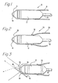
- FIG. 1 illustrates a first embodiment of the present invention;
- FIG. 2 illustrates a second embodiment of the present invention; and
- FIG. 3 illustrates a the embodiment of FIG. 2 with the addition of needle guides.
- Referring generally to FIG. 1, a
sterile sheath apparatus 10 is illustrated in cross-section over anultrasound scanhead 12. Thesheath 10 is comprised of two portions, namely afirst cap portion 14 which extends over theend 16 of theultrasound scanhead 12 and a secondtubular portion 18 which extends back over thecable 20 from theultrasound scanhead 12. In the present embodiment, theentire sheath 10 is made up of a single material. However, thesheath 10 has twodistinct portions 14. 18. Thus, theportion 14 of thesheath 10 which extends over theultrasound scanhead 12 is made to be extremely thick, so it is highly unlikely that thatportion 14 would be punctured during an operative procedure. On the other hand, thetubular portion 18, which extends back over thecable 20, is relatively thin-walled, similar to the latex sheaths heretofore used. in order to provide flexibility while retaining the sterility and waterproof qualities heretofore required. In the present embodiment of the invention, theentire sheath 10 can be constructed of latex or polyethylene. - Referring now to.FIG. 2, a second embodiment of the invention is shown. In the second embodiment the
sheath 24 is comprised of two parts. The first part is acap 26 made of a rigid material designed to fit over theend 16 of ascanhead 12. The second portion of thesheath 24 is the flexible,tubular portion 28 which extends back over thecable 20 from thescanhead 12. Thecap 26 can be comprised of any inexpensive, sterilizable material. such as a plastic. In particular. it may be made of polyethylene. Theproximal tube 28, which which is preferably made of an inexpensive, sterilizable material, such as a sterilizable plastic or latex, can be firmly attached to thecap 26 prior to sterilization by a shrink process, by an adhesive, by a clamp, or by any other method which provides for a sterile, continuous.waterproof seal 34. - Referring now to FIG. 3, a particular feature of the present invention, particularly the version of the invention shown in FIG. 2, is the ability to build
guide channels 36. 38 into the wall of thecap 26. Theguide channels channels 36. 38 can be used to direct the placement of aneedle 40 into a target tissue while keeping theneedle 40 in the plane of thesector scanner 12. Anadditional guide 38 could have a different insertion angle on the opposite side of thecap 26. as shown. Thus. afirst channel 36 on one side of thecap 26 could provide an entry at one angle into the target tissue within the scanned sector while asecond channel 38 on the opposite side of thecap 26 could provide a second entry angle into the sector being scanned. Other devices, such as an outboard directional doppler device (not shown). could also be placed into a channel whereby it would be possible to provide for simultaneous doppler and two-dimentional imaging. - While the present invention has been described with particular reference to a mechanical ultrasound sector scanner, those of ordinary skill in the art will recognize that it may be used, also. with either a phased array, an annular array or a linear scanner in particular applications.
Claims (8)
Applications Claiming Priority (2)
| Application Number | Priority Date | Filing Date | Title |
|---|---|---|---|
| US42293082A | 1982-09-24 | 1982-09-24 | |
| US422930 | 1982-09-24 |
Publications (2)
| Publication Number | Publication Date |
|---|---|
| EP0104618A2 true EP0104618A2 (en) | 1984-04-04 |
| EP0104618A3 EP0104618A3 (en) | 1987-04-29 |
Family
ID=23677000
Family Applications (1)
| Application Number | Title | Priority Date | Filing Date |
|---|---|---|---|
| EP83109482A Withdrawn EP0104618A3 (en) | 1982-09-24 | 1983-09-23 | Sterile sheath apparatus for intraoperative ultrasound scanning |
Country Status (2)
| Country | Link |
|---|---|
| EP (1) | EP0104618A3 (en) |
| JP (1) | JPS5982839A (en) |
Cited By (8)
| Publication number | Priority date | Publication date | Assignee | Title |
|---|---|---|---|---|
| EP0341719A1 (en) * | 1988-05-13 | 1989-11-15 | Opielab, Inc. | Contamination protection system for endoscope control handles |
| EP0477581A1 (en) * | 1990-08-30 | 1992-04-01 | JOHNSON & JOHNSON MEDICAL, INC. | Sterile ultrasound cover tube |
| WO1993011697A1 (en) * | 1991-12-10 | 1993-06-24 | Jose Fernando Losa Dominguez | Prophylactic protector for echographic probes |
| WO1993016640A1 (en) * | 1992-02-27 | 1993-09-02 | Epimed Ag | Device for guiding a puncture device and its use with a hand-held appliance for locating blood vessels |
| WO1993021828A1 (en) * | 1992-04-23 | 1993-11-11 | Deltex Instruments Limited | Ultrasonic oesophageal probe |
| WO1994015532A2 (en) * | 1993-01-18 | 1994-07-21 | Eric Dardel | Blood vessel locating and puncturing device |
| US5419310A (en) * | 1992-11-03 | 1995-05-30 | Vision Sciences, Inc. | Partially inflated protective endoscope sheath |
| WO2010002313A1 (en) | 2008-07-03 | 2010-01-07 | Ascendia Ab | Ultrasound probe cover and method for its production |
Families Citing this family (4)
| Publication number | Priority date | Publication date | Assignee | Title |
|---|---|---|---|---|
| JPH0477907U (en) * | 1990-11-22 | 1992-07-07 | ||
| DE602007013253D1 (en) * | 2006-08-24 | 2011-04-28 | Ultrasound Ventures Llc | STERILE COVER AND NEEDLE GUIDE FOR IMAGING DEVICE |
| JP6067966B2 (en) * | 2011-10-18 | 2017-01-25 | 東芝メディカルシステムズ株式会社 | Ultrasonic probe and ultrasonic diagnostic apparatus |
| JP2014023914A (en) * | 2012-06-20 | 2014-02-06 | Fujifilm Corp | Probe and protective cover therefor |
Citations (4)
| Publication number | Priority date | Publication date | Assignee | Title |
|---|---|---|---|---|
| US3827115A (en) * | 1972-02-22 | 1974-08-06 | Univ Erasmus | Method of manufacturing a catheter |
| DE2518694A1 (en) * | 1975-04-26 | 1976-11-04 | John Robert Naumann | Hygienic disposable casing for electronic thermometer sensors - with thick open end and tapered thin sealed detector end |
| US4250894A (en) * | 1978-11-14 | 1981-02-17 | Yeda Research & Development Co., Ltd. | Instrument for viscoelastic measurement |
| EP0095075A1 (en) * | 1982-05-21 | 1983-11-30 | Siemens Aktiengesellschaft | Ultrasonic transducer |
-
1983
- 1983-09-22 JP JP58176105A patent/JPS5982839A/en active Pending
- 1983-09-23 EP EP83109482A patent/EP0104618A3/en not_active Withdrawn
Patent Citations (4)
| Publication number | Priority date | Publication date | Assignee | Title |
|---|---|---|---|---|
| US3827115A (en) * | 1972-02-22 | 1974-08-06 | Univ Erasmus | Method of manufacturing a catheter |
| DE2518694A1 (en) * | 1975-04-26 | 1976-11-04 | John Robert Naumann | Hygienic disposable casing for electronic thermometer sensors - with thick open end and tapered thin sealed detector end |
| US4250894A (en) * | 1978-11-14 | 1981-02-17 | Yeda Research & Development Co., Ltd. | Instrument for viscoelastic measurement |
| EP0095075A1 (en) * | 1982-05-21 | 1983-11-30 | Siemens Aktiengesellschaft | Ultrasonic transducer |
Cited By (11)
| Publication number | Priority date | Publication date | Assignee | Title |
|---|---|---|---|---|
| EP0341719A1 (en) * | 1988-05-13 | 1989-11-15 | Opielab, Inc. | Contamination protection system for endoscope control handles |
| EP0477581A1 (en) * | 1990-08-30 | 1992-04-01 | JOHNSON & JOHNSON MEDICAL, INC. | Sterile ultrasound cover tube |
| GR910100354A (en) * | 1990-08-30 | 1992-08-31 | Johnson & Johnson Medical | Elastic tube for the supersound covering |
| WO1993011697A1 (en) * | 1991-12-10 | 1993-06-24 | Jose Fernando Losa Dominguez | Prophylactic protector for echographic probes |
| WO1993016640A1 (en) * | 1992-02-27 | 1993-09-02 | Epimed Ag | Device for guiding a puncture device and its use with a hand-held appliance for locating blood vessels |
| WO1993021828A1 (en) * | 1992-04-23 | 1993-11-11 | Deltex Instruments Limited | Ultrasonic oesophageal probe |
| US5419310A (en) * | 1992-11-03 | 1995-05-30 | Vision Sciences, Inc. | Partially inflated protective endoscope sheath |
| WO1994015532A2 (en) * | 1993-01-18 | 1994-07-21 | Eric Dardel | Blood vessel locating and puncturing device |
| WO1994015532A3 (en) * | 1993-01-18 | 1994-09-01 | Eric Dardel | Blood vessel locating and puncturing device |
| WO2010002313A1 (en) | 2008-07-03 | 2010-01-07 | Ascendia Ab | Ultrasound probe cover and method for its production |
| EP2303381B1 (en) * | 2008-07-03 | 2020-10-14 | Ascendia AB | Ultrasound probe cover and method for its production |
Also Published As
| Publication number | Publication date |
|---|---|
| EP0104618A3 (en) | 1987-04-29 |
| JPS5982839A (en) | 1984-05-14 |
Similar Documents
| Publication | Publication Date | Title |
|---|---|---|
| US5469853A (en) | Bendable ultrasonic probe and sheath for use therewith | |
| US11013500B2 (en) | Endocavitary ultrasound probe with biopsy system having two needle guides | |
| EP1686899B1 (en) | Ultrasound guided probe device | |
| EP0104618A2 (en) | Sterile sheath apparatus for intraoperative ultrasound scanning | |
| US4646722A (en) | Protective endoscope sheath and method of installing same | |
| US5335663A (en) | Laparoscopic probes and probe sheaths useful in ultrasonic imaging applications | |
| US6641539B2 (en) | Ultrasonic probe for operation under microscope | |
| EP0821568B1 (en) | An apparatus for ultrasound guided removal of tissue samples | |
| US20100030082A1 (en) | Ultrasound Apparatus | |
| JPH04307050A (en) | Aspiration biopsy apparatus | |
| JP4526298B2 (en) | Ultrasound endoscope device | |
| EP2449956B1 (en) | Distal end hood for endoscope and endoscope system | |
| WO2009138813A1 (en) | Single-use disposable sterile envelope for surgical optics | |
| WO2006129084A1 (en) | Clip for ultrasound probe | |
| KR102633013B1 (en) | Gel supply device for sterile ultrasound treatment | |
| GB2336540A (en) | Flexible endoscope cover | |
| AU2012213939A1 (en) | Ultrasound guided probe device and method | |
| JPS63153053A (en) | Ultrasonic endoscope for puncture |
Legal Events
| Date | Code | Title | Description |
|---|---|---|---|
| PUAI | Public reference made under article 153(3) epc to a published international application that has entered the european phase |
Free format text: ORIGINAL CODE: 0009012 |
|
| AK | Designated contracting states |
Designated state(s): AT BE CH DE FR GB IT LI LU NL SE |
|
| PUAL | Search report despatched |
Free format text: ORIGINAL CODE: 0009013 |
|
| AK | Designated contracting states |
Kind code of ref document: A3 Designated state(s): AT BE CH DE FR GB IT LI LU NL SE |
|
| STAA | Information on the status of an ep patent application or granted ep patent |
Free format text: STATUS: THE APPLICATION IS DEEMED TO BE WITHDRAWN |
|
| 18D | Application deemed to be withdrawn |
Effective date: 19871030 |
|
| RIN1 | Information on inventor provided before grant (corrected) |
Inventor name: SILVERSTEIN, FRED ELI Inventor name: HEYERDAHL, NORMAN EDMUND |