EP0104585B1 - Pot core transformer - Google Patents
Pot core transformer Download PDFInfo
- Publication number
- EP0104585B1 EP0104585B1 EP19830109299 EP83109299A EP0104585B1 EP 0104585 B1 EP0104585 B1 EP 0104585B1 EP 19830109299 EP19830109299 EP 19830109299 EP 83109299 A EP83109299 A EP 83109299A EP 0104585 B1 EP0104585 B1 EP 0104585B1
- Authority
- EP
- European Patent Office
- Prior art keywords
- pedestals
- rims
- transformer according
- pedestal
- winding
- Prior art date
- Legal status (The legal status is an assumption and is not a legal conclusion. Google has not performed a legal analysis and makes no representation as to the accuracy of the status listed.)
- Expired
Links
- 238000004804 winding Methods 0.000 claims description 36
- NJPPVKZQTLUDBO-UHFFFAOYSA-N novaluron Chemical compound C1=C(Cl)C(OC(F)(F)C(OC(F)(F)F)F)=CC=C1NC(=O)NC(=O)C1=C(F)C=CC=C1F NJPPVKZQTLUDBO-UHFFFAOYSA-N 0.000 claims description 17
- 239000000463 material Substances 0.000 claims description 8
- 230000035699 permeability Effects 0.000 claims description 5
- 230000002093 peripheral effect Effects 0.000 claims description 4
- 230000004907 flux Effects 0.000 description 13
- 229910000859 α-Fe Inorganic materials 0.000 description 7
- 230000004048 modification Effects 0.000 description 5
- 238000012986 modification Methods 0.000 description 5
- 230000001939 inductive effect Effects 0.000 description 2
- 230000009467 reduction Effects 0.000 description 2
- 239000004677 Nylon Substances 0.000 description 1
- 238000013461 design Methods 0.000 description 1
- 238000010586 diagram Methods 0.000 description 1
- 238000007598 dipping method Methods 0.000 description 1
- 238000011038 discontinuous diafiltration by volume reduction Methods 0.000 description 1
- 239000006185 dispersion Substances 0.000 description 1
- 230000000694 effects Effects 0.000 description 1
- 238000003780 insertion Methods 0.000 description 1
- 230000037431 insertion Effects 0.000 description 1
- 230000003993 interaction Effects 0.000 description 1
- 229920001778 nylon Polymers 0.000 description 1
- 238000010561 standard procedure Methods 0.000 description 1
- 239000002966 varnish Substances 0.000 description 1
Images
Classifications
-
- H—ELECTRICITY
- H01—ELECTRIC ELEMENTS
- H01F—MAGNETS; INDUCTANCES; TRANSFORMERS; SELECTION OF MATERIALS FOR THEIR MAGNETIC PROPERTIES
- H01F38/00—Adaptations of transformers or inductances for specific applications or functions
- H01F38/08—High-leakage transformers or inductances
-
- H—ELECTRICITY
- H01—ELECTRIC ELEMENTS
- H01F—MAGNETS; INDUCTANCES; TRANSFORMERS; SELECTION OF MATERIALS FOR THEIR MAGNETIC PROPERTIES
- H01F17/00—Fixed inductances of the signal type
- H01F17/04—Fixed inductances of the signal type with magnetic core
- H01F17/043—Fixed inductances of the signal type with magnetic core with two, usually identical or nearly identical parts enclosing completely the coil (pot cores)
Definitions
- the present invention relates to a pot core transformer according to the preamble of claim 1.
- a device of this kind is basically known as a pot core inductive reactance from DE-A 1 439 441.
- the known device is not a pot core transformer because it is provided with only one winding.
- This winding consists of the serial connection of winding portions having different cross-sectional areas.
- a provided air gap only serves to increase the inductivity of the inductive reactance.
- an E-type transformer is known which is provided with an additional yoke in tight contact with the base and the peripheral walls for achieving an additional magnetic dispersion for protectional purposes.
- An important goal in present day design of electrical equipment is reduction in size even when actual miniaturization is not attempted, space and volume reduction is considered desirable.
- One way to accomplish such reduction is to combine functions in a single device structure.
- the present invention makes use of increasing the effective leakage inductance of a transformer winding which comprises shunting a portion of the primary flux of the transformer with a high permeability material or increasing primary flux resistance by an air gap.
- the invention comprises modification of a "pot core" transformer to add the function of one or more additional inductances without changing the characteristics of the device as a transformer.
- Fig. 1 shows that one embodiment of the device may include a transformer 10, having a core 11, a primary winding 12, and a secondary winding 13, combined with a fixed inductance 14 in series with winding 13, and if desired, a fixed inductance 15 in parallel with winding 12.
- Fig. 2 and 3 show the transformer 10 is of the "pot core" type. It comprises a bipartite housing 20 including hollow, coaxial, generally cylindrical sections 21 and 22, of ferrite or other material of high magnetic permeability, which contain windings 12 and 13 respectively.
- Housing 21 comprises an end wall or base 23 from which a peripheral wall 24 extends to a rim 25, and from which a central pedestal 26 extends in the same direction; pedestal 26 is traversed by an axial hole 27.
- Housing section 22 comprises an end wall or base 33 from which a peripheral wall 34 extends to a rim 35, and from which a central pedestal 36 extends in the same direction. Pedestal 36 is traversed by an axial hole 37.
- Winding 12 is mounted in housing section 21 around its pedestal 26, and winding 13 is similarly mounted in housing section 22 about its pedestal 36.
- a suitable fastener 39 such as a nylon screw 40 passes through holes 27 and 37 to hold the sections in assembled relation with the rims and pedestals of the secions in opposition and contact, as shown in Fig. 3.
- a disc or washer 41 of ferrite or other suitable material is located in housing 20 between windings 12 and 13, to act as a magnetic shunt.
- pedestal 36 may be provided with an accurately machined shoulder 42, and rims 25 and 35 may be machined to give cylindrical surfaces 43 accurately coaxial with shoulder 42.
- Disc 41 is circular in section with a circular central bore 45 to fit shoulder 42 with a minimum air gap, and with a periphery at 46 uniformly spaced from rims 43 by a predetermined radial air gap 47.
- a shoulder 52 is machined in rim 25 and pedestals 36 and 26 are machined to give cylindrical surfaces 53 accurately coaxial with shoulder 52.
- a disc 54 of ferrite material has a periphery 55, to engage shoulder 52 with a minimum air gap, and a central bore 56 coaxial therewith to provide an air gap of predetermined width with the pedestal surfaces.
- the same principal and shunt flux paths are present in this structure.
- the housing portions are machined to have the concave cylindrical surfaces 43 of Fig. 3 and the convex cylindrical surfaces 53 of Fig. 4, thus providing both inner and outer radial air gaps with respect to disc 54, which is conveniently mounted with respect to the housing sections by suitable means not shown.
- Fig. 6 shows the structure of Fig. 3 with further modifications.
- pedestal 26 is machined off so as not to contact pedestal 36, but to be spaced axially therefrom by an air gap 63, and has a shoulder 64 to receive a disc 65 of permeable material.
- the air gap 63 is in flux path 61, and functions as an inductor 15 (see Fig. 1) in parallel with the transformer winding.
- a housing 70 has sections 71 and 72 with central pedestal 73 and 74 on which are mounted a primary winding 75 and secondary windings 76 and 77.
- a ferrite disc 80 is mounted on pedestal 73 between winding 75 and 76, and has a radial outer air gap 81 with respect to housing section 71.
- a ferrite disc 82 is mounted on pedestal 74 between windings 75 and 77, and has a radial outer air gap 83 with respect to housing section 72.
- the principal flux paths in this embodiment of the invention are suggested by the arrow 84 on the right of the figure, and links the primary winding 75.
- a secondary flux path is indicated by arrow 85 at the left of the figure, and links primary winding 75 but not secondary windings 76, while another secondary flux path is suggested by arrow 86 and links primary winding 75 but not secondary winding 77.
- circuit equivalent of the structure is shown in Fig. 9, in which effective inductances 89 and 90 are shown in series with windings 76 and 77 respectively.
- FIG. 8 A further modification of the structure of Fig. 7 is shown in Fig. 8.
- pedestal 73 and 74 are cut away, so that they do not engage each other.
- the flux paths are as shown in Fig. 8, passing through the air gap between the pedestals.
- the circuit equivalent of the structure is shown in Fig. 10, where a further effective inductance 91 is shown in parallel with winding 75.
- the invention comprises a means providing magnetic shunt paths in transformers to modify the leakage fluxes in such a fashion as to function as independent inductance units in series or in parallel with transformer windings.
Landscapes
- Engineering & Computer Science (AREA)
- Power Engineering (AREA)
- Microelectronics & Electronic Packaging (AREA)
- Coils Or Transformers For Communication (AREA)
Description
- The present invention relates to a pot core transformer according to the preamble of claim 1. A device of this kind is basically known as a pot core inductive reactance from DE-A 1 439 441. The known device is not a pot core transformer because it is provided with only one winding. This winding consists of the serial connection of winding portions having different cross-sectional areas. A provided air gap only serves to increase the inductivity of the inductive reactance. Furthermore, from FR-A 995 846 an E-type transformer is known which is provided with an additional yoke in tight contact with the base and the peripheral walls for achieving an additional magnetic dispersion for protectional purposes.
- An important goal in present day design of electrical equipment is reduction in size even when actual miniaturization is not attempted, space and volume reduction is considered desirable. One way to accomplish such reduction is to combine functions in a single device structure.
- It is therefore the object of the present invention to provide an arrangement which combines in a single structure the functions of a transformer and of one or more inductors. This object is achieved by the characterizing features of claim 1. Further advantageous embodiments of the present invention may be taken from the subclaims.
- The present invention makes use of increasing the effective leakage inductance of a transformer winding which comprises shunting a portion of the primary flux of the transformer with a high permeability material or increasing primary flux resistance by an air gap.
- With respect to the embodiments shown in the figures of the attached drawing in which like reference numerals identify corresponding elements throughout the several views, the present invention shall be further explained. In those figures
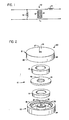
- Fig. 1 is a wiring diagram illustrative of the invention;
- Fig. 2 is an exploded view of a device according to the invention shown schematically;
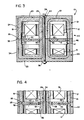
- Fig. 3 is an axial sectional view of the device of Fig. 2;
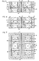
- Fig. 4 and 5 are fragmentary sectional views similar to Fig. 3, showing other embodiments of the invention;
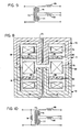
- Fig. 6 is an axial sectional view of a further embodiment of the invention;
- Fig. 7 and 8 show the principal of the invention applied to a transformer having more than two windings; and
- Fig. 9 and 10 are separate equivalents of the structures of Fig. 7 and 8 respectively.
- The invention comprises modification of a "pot core" transformer to add the function of one or more additional inductances without changing the characteristics of the device as a transformer.
- Fig. 1 shows that one embodiment of the device may include a
transformer 10, having a core 11, aprimary winding 12, and asecondary winding 13, combined with a fixedinductance 14 in series with winding 13, and if desired, afixed inductance 15 in parallel with winding 12. - Fig. 2 and 3 show the
transformer 10 is of the "pot core" type. It comprises abipartite housing 20 including hollow, coaxial, generallycylindrical sections windings -
Housing 21 comprises an end wall orbase 23 from which aperipheral wall 24 extends to arim 25, and from which acentral pedestal 26 extends in the same direction;pedestal 26 is traversed by anaxial hole 27.Housing section 22 comprises an end wall orbase 33 from which aperipheral wall 34 extends to arim 35, and from which acentral pedestal 36 extends in the same direction.Pedestal 36 is traversed by anaxial hole 37. -
Winding 12 is mounted inhousing section 21 around itspedestal 26, and winding 13 is similarly mounted inhousing section 22 about itspedestal 36. Asuitable fastener 39 such as anylon screw 40 passes throughholes - A disc or washer 41 of ferrite or other suitable material is located in
housing 20 betweenwindings purpose pedestal 36 may be provided with an accurately machinedshoulder 42, andrims cylindrical surfaces 43 accurately coaxial withshoulder 42. Disc 41 is circular in section with a circular central bore 45 to fitshoulder 42 with a minimum air gap, and with a periphery at 46 uniformly spaced fromrims 43 by a predeterminedradial air gap 47. - In the absence of disc 41 the flux generated by winding 12 is continuous in the high permeability material linking winding 13. The flux path is indicated by the
arrows 61 in Fig. 3. - When disc 41 is present, additional flux paths for winding 12 exist, as shown by
arrows 62; these paths are also in ferrite material except where they pass throughair gap 47. This flux path does not link winding 13, and as a result has the same overall effect as would aseries inductor 14 added, as shown in Fig. 1. To a first approximation the inductance of that inductor is directly proportional to the product of the thickness of the disc multiplied by the perimeter ofperiphery 46, and is inversely proportional to the radial dimension of the gap; strictly speaking, a minimum air gap between bore 45 andshoulder 42 is unavoidable, and modifies the relation slightly, as do other paths between the disc and other parts ofhousing sections - In a modification of the invention shown in Fig. 4, a
shoulder 52 is machined inrim 25 and pedestals 36 and 26 are machined to givecylindrical surfaces 53 accurately coaxial withshoulder 52. - A
disc 54 of ferrite material has aperiphery 55, to engageshoulder 52 with a minimum air gap, and acentral bore 56 coaxial therewith to provide an air gap of predetermined width with the pedestal surfaces. The same principal and shunt flux paths are present in this structure. - In a further modification of the invention shown in Fig. 5, the housing portions are machined to have the concave
cylindrical surfaces 43 of Fig. 3 and the convexcylindrical surfaces 53 of Fig. 4, thus providing both inner and outer radial air gaps with respect todisc 54, which is conveniently mounted with respect to the housing sections by suitable means not shown. - Reference should now be had to Fig. 6 which shows the structure of Fig. 3 with further modifications. Here,
pedestal 26 is machined off so as not to contactpedestal 36, but to be spaced axially therefrom by an air gap 63, and has ashoulder 64 to receive adisc 65 of permeable material. The air gap 63 is influx path 61, and functions as an inductor 15 (see Fig. 1) in parallel with the transformer winding. - It occasionally happens that a series inductor is needed with a transformer having a plurality of secondary windings, which should have minimum interaction. Fig. 7 and 8 show schematically how the desired result may be accomplished according to the present invention. Here, a
housing 70 hassections central pedestal secondary windings ferrite disc 80 is mounted onpedestal 73 between winding 75 and 76, and has a radialouter air gap 81 with respect tohousing section 71. Aferrite disc 82 is mounted onpedestal 74 betweenwindings outer air gap 83 with respect tohousing section 72. - The principal flux paths in this embodiment of the invention are suggested by the
arrow 84 on the right of the figure, and links the primary winding 75. A secondary flux path is indicated byarrow 85 at the left of the figure, and links primary winding 75 but notsecondary windings 76, while another secondary flux path is suggested byarrow 86 and links primary winding 75 but not secondary winding 77. - The circuit equivalent of the structure is shown in Fig. 9, in which
effective inductances windings - A further modification of the structure of Fig. 7 is shown in Fig. 8. Here,
pedestal - It is understood that the various standard techniques for forming the windings on suitable bobbins, with Faraday shields, if desired, mounting them in the housing sections, and again with Faraday shields, if desired, bringing out electrical connections, and varnish dipping or encapsulating may be applied to these structures.
- While the insertion of ferrite discs may slightly increase one dimension of the unit, it avoids the need to provide and mount a separate inductance component.
- From the above it will be evident that the invention comprises a means providing magnetic shunt paths in transformers to modify the leakage fluxes in such a fashion as to function as independent inductance units in series or in parallel with transformer windings.
Claims (9)
Applications Claiming Priority (2)
| Application Number | Priority Date | Filing Date | Title |
|---|---|---|---|
| US42233182A | 1982-09-23 | 1982-09-23 | |
| US422331 | 1982-09-23 |
Publications (2)
| Publication Number | Publication Date |
|---|---|
| EP0104585A1 EP0104585A1 (en) | 1984-04-04 |
| EP0104585B1 true EP0104585B1 (en) | 1986-09-24 |
Family
ID=23674417
Family Applications (1)
| Application Number | Title | Priority Date | Filing Date |
|---|---|---|---|
| EP19830109299 Expired EP0104585B1 (en) | 1982-09-23 | 1983-09-20 | Pot core transformer |
Country Status (2)
| Country | Link |
|---|---|
| EP (1) | EP0104585B1 (en) |
| DE (1) | DE3366470D1 (en) |
Families Citing this family (2)
| Publication number | Priority date | Publication date | Assignee | Title |
|---|---|---|---|---|
| DE4123320A1 (en) * | 1991-07-13 | 1993-01-28 | Diehl Gmbh & Co | Stray field transformer, especially for gas discharge lamps |
| JPH06217062A (en) * | 1993-01-20 | 1994-08-05 | Canon Inc | Ncu circuit and facsimile equipment |
Family Cites Families (6)
| Publication number | Priority date | Publication date | Assignee | Title |
|---|---|---|---|---|
| GB957152A (en) * | 1900-01-01 | |||
| FR797868A (en) * | 1934-02-06 | 1936-05-05 | Transformer with device to increase dispersion | |
| FR995846A (en) * | 1948-09-23 | 1951-12-10 | Thomson Houston Comp Francaise | Improvements in the manufacture of ballast coils |
| DE951826C (en) * | 1952-11-07 | 1956-11-08 | Telefunken Gmbh | Pot core for symmetrical coil arrangement |
| DE1439441A1 (en) * | 1963-09-18 | 1968-12-05 | Sits Soc It Telecom Siemens | Low-loss coil winding for an inductance |
| US3673491A (en) * | 1970-12-21 | 1972-06-27 | Orestes M Baycura | Magnetic square wave voltage generator |
-
1983
- 1983-09-20 DE DE8383109299T patent/DE3366470D1/en not_active Expired
- 1983-09-20 EP EP19830109299 patent/EP0104585B1/en not_active Expired
Also Published As
| Publication number | Publication date |
|---|---|
| DE3366470D1 (en) | 1986-10-30 |
| EP0104585A1 (en) | 1984-04-04 |
Similar Documents
| Publication | Publication Date | Title |
|---|---|---|
| US5977853A (en) | Choke coil for eliminating common mode noise and normal mode noise | |
| US2949591A (en) | Miniature inductive devices | |
| US4639706A (en) | Flyback transformer | |
| US5619400A (en) | Magnetic core structures and construction techniques therefor | |
| US20060006977A1 (en) | Toroidal inductive devices and methods of making the same | |
| JPH01238005A (en) | Modular radio frequency electric source transformer | |
| US5506559A (en) | Choke coil for eliminating common mode noise and normal mode noise | |
| US4689592A (en) | Combined transformer and inductor | |
| US6885270B2 (en) | Wire core inductive devices having a biassing magnet and methods of making the same | |
| EP0154052A1 (en) | Safety transformer | |
| EP0104585B1 (en) | Pot core transformer | |
| EP3683811A1 (en) | Integrated magnetic component | |
| JPH0388310A (en) | Ignition coil | |
| CN216980302U (en) | Inductor | |
| JPH02192705A (en) | Iron core type transformer | |
| GB2243258A (en) | Magnetron for microwave oven | |
| US4326182A (en) | C-Core transformer | |
| US1550889A (en) | Induction device and magnetic circuits for the same | |
| JPH03139806A (en) | Inductance element | |
| JPS6154607A (en) | Transformer | |
| CN217214402U (en) | Resonance transformer | |
| JPH0480525B2 (en) | ||
| US5825272A (en) | Choke coil for suppressing common-mode noise and normal-mode noise | |
| JPH0334899Y2 (en) | ||
| GB2120018A (en) | Transformer |
Legal Events
| Date | Code | Title | Description |
|---|---|---|---|
| PUAI | Public reference made under article 153(3) epc to a published international application that has entered the european phase |
Free format text: ORIGINAL CODE: 0009012 |
|
| AK | Designated contracting states |
Designated state(s): DE FR GB IT NL SE |
|
| 17P | Request for examination filed |
Effective date: 19840903 |
|
| GRAA | (expected) grant |
Free format text: ORIGINAL CODE: 0009210 |
|
| AK | Designated contracting states |
Kind code of ref document: B1 Designated state(s): DE FR GB IT NL SE |
|
| REF | Corresponds to: |
Ref document number: 3366470 Country of ref document: DE Date of ref document: 19861030 |
|
| ET | Fr: translation filed | ||
| ITF | It: translation for a ep patent filed | ||
| PLBE | No opposition filed within time limit |
Free format text: ORIGINAL CODE: 0009261 |
|
| STAA | Information on the status of an ep patent application or granted ep patent |
Free format text: STATUS: NO OPPOSITION FILED WITHIN TIME LIMIT |
|
| 26N | No opposition filed | ||
| ITTA | It: last paid annual fee | ||
| EAL | Se: european patent in force in sweden |
Ref document number: 83109299.4 |
|
| PGFP | Annual fee paid to national office [announced via postgrant information from national office to epo] |
Ref country code: FR Payment date: 19950613 Year of fee payment: 13 |
|
| PGFP | Annual fee paid to national office [announced via postgrant information from national office to epo] |
Ref country code: SE Payment date: 19950619 Year of fee payment: 13 |
|
| PGFP | Annual fee paid to national office [announced via postgrant information from national office to epo] |
Ref country code: GB Payment date: 19950620 Year of fee payment: 13 Ref country code: DE Payment date: 19950620 Year of fee payment: 13 |
|
| PGFP | Annual fee paid to national office [announced via postgrant information from national office to epo] |
Ref country code: NL Payment date: 19950811 Year of fee payment: 13 |
|
| PG25 | Lapsed in a contracting state [announced via postgrant information from national office to epo] |
Ref country code: GB Effective date: 19960920 |
|
| PG25 | Lapsed in a contracting state [announced via postgrant information from national office to epo] |
Ref country code: SE Effective date: 19960921 |
|
| PG25 | Lapsed in a contracting state [announced via postgrant information from national office to epo] |
Ref country code: FR Effective date: 19960930 |
|
| PG25 | Lapsed in a contracting state [announced via postgrant information from national office to epo] |
Ref country code: NL Effective date: 19970401 |
|
| GBPC | Gb: european patent ceased through non-payment of renewal fee |
Effective date: 19960920 |
|
| NLV4 | Nl: lapsed or anulled due to non-payment of the annual fee |
Effective date: 19970401 |
|
| PG25 | Lapsed in a contracting state [announced via postgrant information from national office to epo] |
Ref country code: DE Effective date: 19970603 |
|
| EUG | Se: european patent has lapsed |
Ref document number: 83109299.4 |
|
| REG | Reference to a national code |
Ref country code: FR Ref legal event code: ST |
|
| REG | Reference to a national code |
Ref country code: FR Ref legal event code: ST |