EP0104487A2 - Verarbeitungssystem für eine logische Programmiersprache - Google Patents
Verarbeitungssystem für eine logische Programmiersprache Download PDFInfo
- Publication number
- EP0104487A2 EP0104487A2 EP83108600A EP83108600A EP0104487A2 EP 0104487 A2 EP0104487 A2 EP 0104487A2 EP 83108600 A EP83108600 A EP 83108600A EP 83108600 A EP83108600 A EP 83108600A EP 0104487 A2 EP0104487 A2 EP 0104487A2
- Authority
- EP
- European Patent Office
- Prior art keywords
- predicate
- argument
- clause
- head
- entries
- Prior art date
- Legal status (The legal status is an assumption and is not a legal conclusion. Google has not performed a legal analysis and makes no representation as to the accuracy of the status listed.)
- Granted
Links
Images

Classifications
-
- G—PHYSICS
- G06—COMPUTING OR CALCULATING; COUNTING
- G06F—ELECTRIC DIGITAL DATA PROCESSING
- G06F9/00—Arrangements for program control, e.g. control units
- G06F9/06—Arrangements for program control, e.g. control units using stored programs, i.e. using an internal store of processing equipment to receive or retain programs
- G06F9/44—Arrangements for executing specific programs
- G06F9/448—Execution paradigms, e.g. implementations of programming paradigms
- G06F9/4496—Unification in logic programming
Definitions
- This invention relates to an electronic digital computer and, more particularly, to a system for executing Prolog programs, namely, programs written in a programming language referred to in the art as Prolog (PROgramming in LOGic).
- a dash with an arrowhead - is a logic symbol.
- the expressions on both sides of the logic symbol are called predicates, respectively.
- the word exemplified by “likes” and “fruits” are referred to herein as predicate names, respectively.
- the words "Jack” and "xthings” are called arguments, respectively.
- the argument preceded by an asterisk x is a variable argument.
- the argument without the asterisk is a constant argument.
- Each predicate represents an event and is defined by a predicate name and a permutation of one or more arguments. As will become clear as the description proceeds, it is important to direct attention to the order in which the arguments are arranged in a predicate. The word "permutation" is therefore used even when there is only one argument in a predicate.
- the lefthand side of the logic symbol is called a head and the righthand side, a body.
- a clause may have only either the head or the body.
- a clause having both the head and the body is called a regular clause.
- a clause having only the head is called a declaratory clause.
- the head of each declaratory clause need not be followed by the logic symbol but directly by a stop.
- a clause having the body alone, is named an interrogatory clause. In each interrogatory clause, the body should be preceded by the logic symbol.
- the predicate of the head and the predicate of the body are herein called a head predicate and a body precicate.
- the head of a regular or a declaratory clause consists of only one head predicate. It is therefore possible to refer to a head also as a head predicate.
- the body of a regular or an interrogatory clause consists of one or more body predicates. When a body consists of N predicates, a comma is interposed between two adjacent ones of the body predicates as3
- Predicate H represents a certain head predicate.
- Predicate 1 through “Predicate N” represent body predicates, N in number.
- the comma used between the body predicates is another logic symbol which means AND. Stated otherwise, the event represented by the head predicate is true only when all events represented by "Predicate 1" through “Predicate N” hold. Incidentally, it is possible to understand that a declaratory clause has zero body predicate and that an interrogatory clause, zero head predicate.
- each Prolog program is represented for a program memory by a plurality of entries given in a predetermined number of formats.
- Each entry has first through F-th fields where F represents a preselected natural number which is greater than unity.
- the F-th fields of the entries represent the formats in which the respective entries are formed. In other words, the F-th fields serve as discriminators indicative of the respective formats.
- the first through the (F-l)-th fields of each entry indicate relationships which the entry under consideration has relative to different ones of the entries so that the entries altogether represent the program.
- a system for executing a Prolog program which system comprises a program memory comprising a plurality of memory addresses for storing entries, respectively.
- the entries are given in a predetermined number of formats.
- Each entry has first through F-th fields where F represents a preselected natural number which is greater than unity.
- the F-th fields of the entries represent the formats of the respective entries.
- the first through the (F-l)-th fields of the entries indicate relationships which each entry has relative to different ones of the entries so that the entries represent the program.
- the system furthermore comprises accessing means for accessing the memory addresses one at a time, first through (F-l)-th pointer registers for storing the first through the (F-l)-th fields of one entry of the memory address accessed by the accessing means as first through (F-l)-th pointers, respectively, and selecting means responsive at least to the F-th field of the above-mentioned one entry for selecting one of the pointer registers at a time.
- the selecting means is coupled to the accessing means to make the accessing means access the memory addresses following the relationships indicated by the pointers of the successively selected ones of the pointer registers.
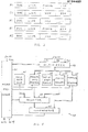
- Fig. 1 an example of Prolog programs will be described at first in order to facilitate an understanding of the present invention.
- the program is written as a sequence of first through fourth clauses. Only two predicate names p1 and P2 are used in the program, which will be called first and second predicate names, respectively.
- Four arguments A, B, C, and xX are used in .the program, which will be named first through fourth arguments.
- the first through the third arguments are constant arguments.
- the first through the third arguments have constant argument values or names.
- the fourth argement is a variable argument or has a variable argument value or name as indicated by an asterisk x.
- the first clause is a regular clause,
- the first clause has a head predicate defined by the first predicate name and a permutation of the first and the fourth arguments.
- the first clause has a body which consists of only one body predicate defined by the second predicate name and the fourth argument.
- the second and the third clauses are declaratory clauses.
- the head predicate of the second clause is defined by the second predicate name and the second argument and the head predicate of the third clause, by the second predicate name and the third argument.
- the fourth clause is an interrogatory clause.
- the body consists of only one body predicate, which is defined by the first predicate name and a permutation of the first and the fourth arguments. It may be mentioned here that a Prolog program includes at least one interrogatory clause and that the interrogatory clause or clauses define an interrogatory instruction.
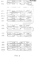
- a Prolog program executing system comprises a program memory 21 for storing a Prolog program which is to be executed.
- the program is represented by a plurality of table entries or control words to be stored in memory addresses, respectively, which the program memory 21 comprises.
- the memory addresses are accessed one at a time by an address signal supplied from a register selector 22 as will later be described.
- each table entry is given in one of table formats of five types.
- the table formats are a process table format PT, a clause table format CT, a head table format HT, a body table format BT, and an argument table format AT.
- each table entry has first through fourth fields.
- the field depicted for each table entry on the leftmost end of the figure will be called the fourth field.
- the fields right to the fourth field of each table entry will successively be called the first through the third fields.
- the fourth fields of the respective table entries serve as table or entry discriminators DISC indicative of the respective table formats. What are indicated by the first through the third fields of.each table entry, depends primarily on the table format of that table entry and will soon be described. It may be mentioned here that each first field serves as a link indicator LINK of the nature which will shortly be described.
- the table entries given in the process, the clause, the head, the body, and the argument table formats, will be referred to as process, clause, head, body, and argument table entries, respectively.
- the process table entries are formed for different or unique ones, respectively, of the predicate names used in the head predicates of the clauses.
- the clause table entries are formed for the respective clauses.
- the head table entries are formed for the respective arguments used in each of the head predicates of the clauses.
- the body table entries are formed for the respective predicate names used in each of the body predicates of the clauses.
- the argument table entries are formed for the respective arguments used in each of the body predicates of the clauses.
- clause table entries represent the respective clauses.
- the process and the body table entries are linked to one another by the predicate names and may collectively be called predicate name table entries.
- the head and the argument table entries are related to one another by the argument values and may collectively be named argument value table entries. It is to be noted in this connection that the third argument is included only in the head predicate of the third clause. A head table entry formed for such an argument is related only to the head table entry under consideration.
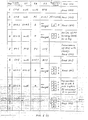
- first and second predicate names Pl and P2 are used as pointed out hereinabove throughout the program exemplified in Fig. 1.
- the different predicate names used in the head predicates of the clauses are also the first and the second predicate names P1 and P2.
- First and second process table entries PT1 and HT2 are therefore formed for the first and the second predicate names Pl and P2, respectively, and stored in the program memory 21 (Fig. 2) at memory addresses which may be designated by PT1 and PT2, respectively, merely for simplicity of denotation.
- the first field, namely, the link indicator LINK (Fig. 3), of each process table entry indicates the memory address of another process table entry. More specifically, the link indicator of a process table entry represents one of the memory addresses that is accessed next subsequent to the memory address of the process table entry under consideration insofar as the process table entries are concerned.
- the fact that there are no other table entries of this kind, is indicated by a null code. It is possible to understand that the null code is also indicative of a memory address of "another" process table entry. Stated otherwise, the null code means that there is no other memory addresses of the process table entries.
- the first process table entry PT1 is accesed at first of all process table entries.
- the link indicator of the first process table entry PT1 therefore represents the memory address PT2 (Fig. 4) of another of the process table entries.
- the link indicator of the second process table entry PT2 gives the null code (Fig. 4).
- the second field of each process table entry serves as a predicate name indicator PNAME (Fig. 3) indicative of the predicate name for which the process table entry in question is formed.
- the predicate name indicators of the first and the second process table entries PT1 and PT2 therefore represent the first and the second predicate names P1 and P2 (Fig. 4).
- the predicate name indicotor PNAME indicates the memory address of another table entry.
- First through fourth clause table entries CT1 to CT4 are formed for the first through the fourth clauses, respectively.
- the first predicate name Pl is included only in the first clause insofar as the head predicate is concerned.
- the second predicate name P2 is included in common in the head predicates of the second and the third clauses.
- the memory address of the second clause table entry CT2 is the earliest of the memory adderses of the clause table entries for the clauses including the second predicate name P2 in common in the head predicates. More particularly, the second clause table entry CT2 is accessed prior to the third clause table entry CT3.
- the clause table indicator CTP of the process table entry represents the memory address of a clause table entry which is accessed the earliest of the clause table entries formed for the clauses including the predicate name under consideration in common in the head predicates.
- the clause table indicators of the first and the second process table entries PT1 and PT2 therefore indicate the memory addresses of the first and the second clause table entries CT1 and CT2 (Fig. 4), respectively,
- the link indicator LINK of a clause table entry formed for each clause including a predicate name in the head predicate indicates the memory address of a clause table entry formed for another clause which also includes the predicate name in question in the head predicate.
- the link indicator of the first clause table entry CT1 is therefore the null code (Fig. 4).
- the link indicator of the second clause table-entry CT2 indicates the memory address of the third clause table entry CT3 (Fig. 4).
- the link indicator of the third and the fourth clause table entries CT3 and CT4 are the null codes (Fig. 4).
- each clause table entry serves as head and body table indicators or pointers HTP and HTP (Fig. 3), respectively.
- the head and the body table entries must therefore be described more in detail.
- the two arguments included in the head predicate of the first clause are referred to hereinabove as the first and the fourth argument A and xX.
- the primary first head table entry HT1.1 is formed for the first argument that stands foremost in the permutation.
- the secondary first head table entry HT1.2 is formed for the fourth argument that stands in the permutation next subsequent to the foremost standing argument.
- the link indicator LINK of a head table entry formed for an argument comprised by a head predicate indicates the memory address of a head table entry formed for another argument of the head predicate under consideration. Attention should be directed in this connection to the permutation of the argument(s).
- the "another" argument should be an argument that stands next following the first-mentioned argument in the permutation.
- the fourth argument xX is followed in that head predicate by no argument.
- the link indicator of the primary and the secondary first table entries HT1.1 and HT1.2 therefore represent the memory address of the-secondary first head table entry HT1.2 and the null code (Fig. 4), respectively.
- the link indicators of the second and the third head table entries HT2 and HT3 are the null codes (Fig. 4).
- the second field of each head table entry serves as an argument value indicator or pointer ARG (Fig. 3) indicative of the argument for which the head table entry under consideration is formed.
- the argument value indicators of the primary and the secondary first head table entries HT1.1 and HT1.2 therefore represent the first and the fourth arguments A and x (Fig. 4), respectively. Inasmuch as the program includes only one variable argument, the fourth argument is designated merely by the asterisk.
- the argument value indicators of the second and the third head table entries HT2 and HT3 are representative of the second and the third arguments B and C (Fig. 4).
- the third field of each head table entry is not used as indicated by a stroke in Figs. 3 and 4.
- a first body table entry BT1 is formed for the second predicate name P2 included in each of the body predicate(s) of the first clause. No body table entries are formed for the second and the third clauses which have no body predicate. If formed, the body table entries should be named second and third body table entries.
- a fourth body table entry BT4 is formed for the first predicate name Pl included in each of the body predicate(s) of the fourth clause.
- the link indicator LINK of a body table entry formed for a predicate name of one of the body predicates of a clause indicates the memory address of a body table entry formed for the predicate name of another of the body predicates of the clause under consideration.
- a plurality of body predicates of a clause are combined by AND into a body of the clause in question. The order of the body predicates in each clause is therefore immaterial.
- the link indicators of the first and the fourth body table entries BT1 and BT4 are the null codes (Fig. 4).
- the second field of each body table entry serves as a predicate name indicator PNAME (Fig. 3) as in the process table entry.
- the predicate name indicator of a body table entry indicates the predicate name for which the body table entry is question is formed.
- the first and the fourth body table entries BT1 and BT4 therefore include predicate name indicators representative of the second and the first predicate names P2 and Pl (Fig. 4), respectively.
- the third field of each body table entry serves as an argument table indicator or pointer ATP (Fig. 3).
- the argument table indicator will be described after the argument table entries are described later in the following.
- the head table indicator HTP of a clause table entry represents the memory address of the earliest accessed one of the head table entries, such as HT1.1 and HT1.2, formed for the respective arguments of the head predicate of the clause for which the clause table entry under consideration is formed.
- the head table indicator of a clause table entry for a clause represents the memory address of a head table entry formed for the argument which stands foremost in the permutation in the head predicate of the clause in question.
- the head table indicator of the first clause table entry CT1 therefore indicates the memory address of the primary first head table entry HT1.1 (Fig. 4).
- the head table indicators of the second and the third clause table entries CT2 and CT3 represent the memory addresses of the second and the third head table entries HT2 and HT3 (Fig. 4).
- the head table indicator of the fourth clause table entry CT4 is the null code (Fig. 4).
- the body table indicator BTP of a clause table entry formed for a clause represents the memory address of the body table entry that is formed for the predicate name of one of the body predicates of the clause under consideration.
- the body table indicator of the first clause table entry CTi indicates the memory address of the first body table entry BT1 (Fi g. 4).
- the body table indicators of the second and the third clause table entries CT2 and CT3 are the null codes (Fig. 4).
- the body table indicator of the fourth clause table entry CT4 represents the memory address of the fourth body table entry BT4 (Fig. 4).
- Only one first argument table entry AT1 is formed for the argument(s) in the body predicate(s) of the first clause. No argument table entries are formed for the second and the third clauses. If formed, such argument table entries should be named second and third argument table entries.
- Primary and secondary fourth argument table entries AT4.1 and AT4.2 are formed for two arguments included in each of the body predicate(s) of the fourth clause. As described in conjunction with the first head table entries HTl's, the primary one is for the argument that stands foremost in the permutation of arguments of each body predicate. The secondary one is for the argument that next stands in the permutation.
- the link indicator LINK of an argument table entry foremd for each argument of each body predicate represents the memory address of an argument table entry for the argument that next follows the argument in question in the permutation of arguments in the body predicate under consideration.
- the first argument table entry AT1 therefore includes a link indicator of the null code (Fig. 4).
- the primary fourth argument table entry AT4.1 includes a link indicator representative of the memory address of the secondary fourth argument table entry AT4.2 (Fig. 4).
- the link indicator of the secondary fourth argument table entry AT4.2 is the null code (Fig. 4).
- the second field of an argument table entry formed for each argument of each body predicate serves as an argument value indicator ARC (Fig. 3) representative of the argument in question.
- the argument value indicator of the first argument table entry AT1 therefore indicates the fourth argument x (Fig. 4).
- the argument value indicators of the primary and the secondary - fourth argument table entries AT4.1 and AT4.2 represent the first and the fourth arguments A and x (Fig. 4), respectively.
- each table entry is read from the memory address accessed in the program memory 21 by the address signal into a read-out register 23 as a read-out table entry.
- the read-out register 23 has first through fourth fields for the first through the fourth fields of the read-out table entry, respectively.
- the first through the third fields of the read-out table entry will be designated by Rl, R2, and R3, respectively.
- the first field Rl is a link indicator LINK.
- the second field R2 represents a predicate name indicator PNAME, an argument value indicator ARG, or a head table indicator HTP.
- the third field R3 indicates one of the clause, the body, and the argument table indicators CTP, BTP, and ATP. As the case may be, the third field R3 is idle as indicated by a stroke in Figs. 3 and 4.
- the first through the fourth fields of the read-out table entry are supplied to a control unit 25.
- the first through the third fields Rl to R3 are delivered towards first through third pointer registers 26, 27, and 28, respectively, and are stored therein as first through third pointers, respectively.
- the control unit 25 may produce a pointer register set signal in the manner presently be described.
- the control unit 25 supplies the first through third register selection signals to the register selector 22 to make the same select the first through the third pointer registers 26 to 28, respectively.
- the control unit 25 feeds an additional register selection signal to the register selector - 22 to make the same select an additional register 29, which is loaded with an address signal by the control unit 25.
- the register selector 22 thus selects one of the registers 26 through 29 at a time to deliver the contents of the selected register as the address signal to the program memory 21,
- a conventional computer comprises only one address register for a program memory. Furthermore, the memory address is specified by a specific field of each internal expression. It follows that a plurality of steps are indispensable on selecting each memory address from a plurality of fields and on storing the memory address in the address register.
- the Prolog program executing system exemplified in Fig. 2 is capable of dealing with the internal expressions as they are. Moreover, provision of a plurality of registers makes it possible to effectively execute the program represented by such internal expressions.
- control unit 25 may comprise a microprocessor 31 supplied with the fourth field of the read-out table entry from the read-out register 23 (Fig. 2) to decode the table discriminator DISC (Fig. 3).
- a multiplexer 33 is supplied with the first through the third fields Rl to R3 from the read-out register 23.
- the microprocessor 31 is timed to deliver first through third multiplexer selection signal to the multiplexer 33 to make the same select the first through the third fields Rl to.R3, respectively, as a multiplexer output signal.
- the multiplexer .output signal is delivered towards a working register 35, a predicate name register 36, and a stack memory 37.
- the stack memory 37 has a plurality of stack addresses. One of the stack addresses is indicated, as a top address by a top of stack pointer 39. It is possible in the manner known in the art to make the top of stack pointer 39 indicate the stack addresses 0, 1, 2, 3 , 4, and so forth as the top address and to carry out push down of the stack memory 37. It is also possible to make the top of stack pointer 39 indicate a stack address to make the stack memory 37 produce a stack output signal.
- the microprocessor 31 feeds a working register set signal to the working register 35 to set the multiplexer output signal therein.
- the working register 35 produces its content as a working register output signal.
- the microprocessor 31 produces a predicate name set signal immediately after the second multiplexer selection signal instead of the working register set signal.
- the predicate name set signal sets the second field R2 of each body table entry in the predicate name register 36.
- the second field R2 is what is produced by the multiplexer 33 and is the predicate name indicator PNAME (Fig. 3).
- the predicate name register 36 produces the predicate name indicator PNAME stored therein, as a predicate name output signal.
- the multiplexer output signal produced in response to the second multiplexer selection signal is stored in the stack memory 37 at the top address as well as in the working register 35.
- the multiplexer output signal is the argument value indicator ARG (Fig. 3) of the head or the argument table entry stored in the read-out register 23 as the read-out table entry.
- a variable argument is rewritten in the stack address into a stack address pointer as will later be described.
- a null code generator 41 is for generating the null code as a null code output signal.
- An internal selector 43 is supplied with the null code output signal of the null code generator 41, the predicate name output signal of the predicate name register 36, and the stack output signal of the stack memory 37.
- the microprocessor 31 produces a first internal selector selection signal to make the internal selector 43 select as a selector output signal the null code output signal.
- the table discriminator DISC indicates the process table format PT (Fig. 3)
- the microprocessor 31 produces a second internal selector selection signal immediately after the working register set signal.
- the second internal selector selection signal makes the internal selector 43 produce the predicate name output signal as another selector output signal.
- the microprocessor 31 When the table discriminator DISC represents the argument table format AT, the microprocessor 31 produces a third internal selector selection signal substantially concurrently with the working register set signal.
- the third internal selector selection signal makes the internal selector 43 select the stack output signal as still another selector output signal.
- the microprocessor 31 may keep the first internal selector selection signal unless it temporarily swtches the first internal selector selection signal to the second or the third internal selector selection signal.
- a comparator 45 is for comparing the working register output signal of the working register 35 with the selector output signal of the internal selector 43.
- a comparison result signal thereby produced is fed back to the microprocessor 31.
- the comparison result signal indicative of coincidence and incoincidence will be named a coincidence and an incoincidence signal.
- the microprocessor 31 delivers the pointer register set signal to the first through the third pointer registers 26 to 28 (Fig. 2) through a connection (not shown).
- the microprocessor 31 For each table entry read out into the read-out register 23 from the program memory 21, the microprocessor 31 decodes the table discriminator DISC (Fig. 3) at first although the table discriminator is given in the "fourth" field of the read-out table entry. The microprocessor 31 holds the decoded table discriminator until the next following table discriminator is supplied thereto and decoded. Other operation of the microprocessor 31 will become clear from the following.
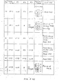
- Fig. 6 (Figs. 6 (1) and (2)) together with Figs. 2, 4, and 5, operation will be described for the program exemplified in Fig. 1 and represented by the table entries of the table formats illustrated with reference to Fig. 3.
- the microprocessor 31 has loaded the additional register 29 with an address signal indicative of the memory address of the fourth clause table entry CT4 (Figs. Wand 6) and has supplied the register selector 22 with the additional register selection signal.
- the address signal makes the program memory 21 produce the fourth clause table entry CT4, which is stored in the read-out register 23 as a read-out table entry.
- the microprocessor 31 detects that the table discriminator DISC (Fig. 3) indicates the clause table format CT (Fig. 3).
- the detected table discriminator is kept in the microprocessor 31 throughout the first step 1 of operation.
- the working register 35 is loaded with the null code given by the first field Rl.
- the comparator 43 is supplied with the null code output signal of the null code generator 41.
- the comparator 45 produces the coincidence signal, namely, the comparison result signal representative of coincidence.
- the comparison result signal is retained in the microprocessor 31 in addition to the detected table discriminator.
- the second field R2 is substituted in the working register 35 for the first field Rl.
- the second field R2 is, however, again the null code in the case of the fourth clause table entry CT4.
- the comparator 45 produces the coincidence signal.
- the comparison result signal is also kept in the microprocessor 31.
- the microprocessor 31 is informed of the fact that the head table indicator HTP (Fig. 3) is the null code, namely, that the fourth clause table entry CT4 is for an interrogatory clause.
- the third field R3 is written in the working register 35.
- the third field R3 represents the memory address of the fourth body table entry BT4 (Figs. 4 and 6).
- the comparator 45 produces the incoincidence signal.
- the microprocessor 31 produces the pointer register set signal to set the third field R3 in the third pointer register 28 as a pointer to the memory address of the fourth body table entry BT4.
- the microprocessor 31 responds to the table discriminator DISC indicative of the clause table format CT and the coincidence signal produced for the head table entry HTP (Fig. 3) and kept therein to supply the register selector 22 with the third register selection signal.
- the fourth body table entry BT4 is read from the program memory 21 into the read-out register 23 as a new read-out table entry.
- the microprocessor 31 detects the table discriminator DISC for the body table format BT (Fig. 3). The newly detected table discriminator is substituted in the microprocessor 31 for the table discriminator detected in the first step 1 of operation.
- the comparison result signal is retained in the microprocessor 31 until the steps come to an end for the interrogatory clause dealt with during the first step 1 of operation. It is to be noted that the comparison result signal is kept in the microprocessor 31 although a like comparison result signal indicative of the coincidence or the incoincidence is produced for the link indicator LINK (Fig. 3) of each table entry read into the read-out register 23 and retained in the microprocessor 31 during each step of operation.
- the microprocessor 31 makes the predicate name set signal follow the second multiplexer selection signal and does not produce the working register set signal.
- the predicate name register 36 is loaded with the second field R2 representative of the first predicate name Pl.
- the third field R3 is set in the working register 35.
- the comparator 45 produces the incoinicidence signal.
- the pointer register set signal rewrites the previous pointer in the third pointer register 28 into a new pointer to the memory address of the primary fourth argument table entry AT4.1.
- the microprocessor 31 responds to the table discriminator DISC representative of the body table format BT and sends the third register selection signal to the register selector 22.
- the primary fourth argument table entry AT4.1 is stored in the read-out register 23.
- the microprocessor 31 detects the table discriminator DISC representative of the argument table format AT (Fig. 3). As before, the newly detected table discriminator is substituted in the microprocessor 31 for the previously detected and retained table discriminator.
- the first field Rl is stored in the working register 35.
- the comparator 45 produces the incoincidence signal.
- the comparison result signal indicative of the incoincidence is retained in the microprocessor 31 during the third step 3 of operation in addition to the comparison result signal produced in the second, step 2 of operation for the link indicator
- the pointer register set signal sets the first field Rl in the first pointer register 26.
- the second field R2 is set in the working register 35.
- the microprocessor 31 produces the third selector selection signal rather than the first selector selection signal. No signal is stored as yet in the stack memory 37.
- the comparator 45 therefore produces the incoincidence signal.
- the table discriminator for the argument table format AT makes the second multiplexer selection signal store the second field R2 in the stack memory 37 at the stack address 0 indicated by the top of stack pointer 39.
- the second field R2 represents the first argument A.
- the third pointer register 28 keeps the pointer to the memory address of the primary fourth argument table entry AT4.1 unchanged
- the microprocessor 31 responds to the table discriminator DISC representative of the argument table format AT and the incoincidence signal produced for the first field R1 and kept therein to deliver the first register selection signal to the register selector 22.
- the secondary fourth argument table entry AT4.2 is stored in the read-out register 23.
- the microprocessor 31 detects that the table discriminator DISC again indicates the argument table format AT.
- the table discriminator indicative of the argument table format AT is retained in the microprocessor 31.
- the first field Rl is set in the working register 35.
- the first field Rl gives the null code.
- the comparator 45 therefore produces the coincidence signal
- the second multiplexer selection signal stores the second field R2 in the stack memory 37 at the stack address 1.
- the first argument A stored in the stack address 0 is pushed down.
- the second field R2 stored in the stack address 1 represents the fourth argument x.
- the pointer to the memory address of the primary fourth argument table entry AT4.1 is still kept unchanged in the third pointer register 28.
- the pointer to the primary fourth argument table entry AT4.1 is, however, already used before beginning of the fourth step 4 of operation and is no more used.
- the microprocessor 31 responds to the table discriminator DISC for the argument table format AT and the coincidence signal produced for the first field Rl and kept therein to load the additional register 29 with an address signal representative of the memory address of the first process table entry PTl. Furthermore, the microprocessor 31 delivers the additional register selection signal to the register selector 22.
- the first process table entry PT1 is read into the read-out register 23. It is possible to understand that this is to check whether or not the predicate name indicator PNAME (Fig. 3) given by the second field R2 of the fourth body table entry BT4 and stored in the predicate name register 26, is coincident with the predicate name indicator PNAME given in the first process table entry PT1. The check is indicated in Fig. 6 by "search of PT [process table entries] by using (PNR) as a key.”
- the microprocessor 31 detects that the table discriminator DISC is for the process table format PT (Fig. 3).
- the table discriminator kept in the microprocessor 31 is changed from that for the argument table format AT to the newly detected one for the process table format PT.
- the first field Rl is not a null code.
- the comparator 45 therefore supplies the microprocessor 31 with the incoincidence signal.
- the microprocessor 31 produces the pointer register set signal, which loads the first field Bl in the first pointer register 26.
- the first field Rl represents the memory address of the second process table entry PT2.
- the second field R2 is set in the working register 35.
- the microprocessor 31 produces the second selector selection signal rather than the first selector selection signal.
- the comparator 45 compares the working register output signal of the working register 35 with the predicate name output signal of the predicate name register 36. Both represent the first predicate name Pl.
- the comparator 45 produces the coincidence signal.
- the comparison result signal is also retained in the microprocessor 31.
- the microprocessor 31 Responsive to the incoincidence signal produced for the third field R3, the microprocessor 31 produces the pointer , register set signal to store the third field R3 in the third pointer register 28.
- the third field R3 represents the memory address of the first clause table entry CTl.
- the microprocessor 31 detects the table discriminator DISC for the clause table format CT.
- the microprocessor 31 keeps the table discriminator of the clause table format CT in place of the previously detected table discriminator for the process table format PT.
- the first field Rl gives the null code.
- the comvarator 45 produces the coincidence signal.
- the second field R2 is, however, not a null code.
- the comparator 45 supplies the microprocessor 31 with the incoincidence signal.
- the microprocessor 31 produces the pointer register set signal to store the second field R2 in the second pointer register 27.
- the second field R2 represents the memory address of the primary first head table entry HT1.1.
- the null code output signal of the null code generator 41 is compared with the third field R3 selected by the third multiplexer selection signal.
- the comparator 45 produces the incoincidence signal.
- the microprocessor 31 produces the pointer register set signal to set the third field R3 in the third pointer register 28.
- the third field R3 indicates the memory address of the first body table entry BT1.
- the table discriminator DISC retained in the microprocessor 31, indicates the clause table format CT.
- the second field R2 is, however, not a null code.
- the microprocessor 31 therefore produces the second register selection signal for the next step rather than the third register selection signal.
- the primary first head table entry HT1,1 is read into the read-out register 23.
- the microprocessor 31 detects the table discriminator DISC for the head table format HT (Fig. 3).
- the table discriminator indicative of the head table format HT is now retained in the microprocessor 31.
- the first field Rl is not a null code.
- the comparator 45 produces the incoincidence signal.
- the microprocessor 31 produces the pointer register set signal to store the first field Rl in the first pointer register 26.
- the first field Rl represents the memory address of the secondary first head table entry HT1. 2 .
- the second multiplexer selection signal stores the second field R2 in the stack memory 37 at the stack address 2.
- the second field R2 represents the fourth argument x.
- the third pointer register 28 keeps the address signal for the first body table entry BT1 unchanged.
- the pointer kept in the third pointer register 28 is used later in the following.
- the stack memory 37 is loaded with the first argument A, the fourth argument x, and again the first argument A in the stack addresses 0, 1, and 2, respectively.
- the microprocessor 31 responds to the table discriminator DISC for the head table format HT and the incoincidence signal produced for the first field Rl and kept therein to supply the register selector 22 with the first register selection signal.
- the secondary first head table entry HT1.2 is read into the read-out register 23.
- the microprocessor 31 again detects the table discriminator DISC for the head table format HT.
- the first field Rl is the null code.
- the comparator 45 produces the coincidence signal.
- the microprocessor 31 produces the second multiplexer selection signal and the working register set signal.
- the microprocessor 31 furthermore produces the third selector selection signal.
- the second field R2 is stet in the working register 35 and is compared with the argument A stored in the stack address 2.
- the comparator 45 produces the incoidnicedne signal.
- the second field R2 selected by the second multiplexer selection signal is stored in the stack memory 37 at the stack address 3. The contents in the stack addresses 0 through 2 are pushed down.
- the third field R3 is idle.
- the third pointer register 28 still keeps the memory address of the first body table entry BT1 unchanged.
- the stack memory 37 is loaded with the first argument A, the fourth argument x, again the first argument A, and again the fourth argument x in the stack addresses 0, 1, 2, and 3, respectively. It is to be noted that the microprocessor 31 now retains, among others, the table'discriminator DISC for the argument table format AT and the coincidence signal produced for the first field Rl. The next step is to compare contents of the stack addresses 0 and 2 with contents of the stack addresses 1 and 3, respectively. If the contents are coincident, the variable argument x stored in the stack address 3 is rewritten into a stack address pointer to the stack address 1 in the manner known in the art.
- a ninth step 9 of operation the microprocessor 31 carries out the comparison. Inasmuch as the coincidence holds between the contents of the stack addresses 0 and 2 and between the contents of the stack addresses 1 and 3, the content of the stack address 3 is rewritten into the pointer to the stack address 1 as symbolically depicted in Fig. 6.
- the microprocessor 31 furthermore responds for-the next step to the table discrininator DISC for the argument table format AT and the coincidence signal produced for the first field Rl to supply the third register selection signal to the register selector 22.
- the first body table entry BT1 is now stored in the read-out register 23.
- the table discriminator DISC for the body table format BT is detected by the microprocessor 31 and retained therein.
- the second predicate name P2 is substituted in the predicate name register 36 for the first predicate name Pl.
- the third field R3 is not a null code and is therefore stored in the third pointer register 28.
- the third field R3 indicates the memory address of the first argument table entry AT1.
- the above-described storage of the second predicate name P2 in the predicate name register 36 is indicated in Fig. 6 by "P2 - (PNR)."
- the conteris of the stack memory 37 are not different from those obtained in the ninth step 9 of operation.
- the microprocessor 31 responds to the table discriminator DISC indicative of the body table format BT to deliver the third register selection signal to the register selector 22.
- the table discriminator DISC for the argument table format AT is sensed by the microprocessor. 31 and kept therein.
- the microprocessor 31 After storage of the second field R2 in the working register 35, the microprocessor 31 produces the third selector selection signal to select the stack output signal, namely, the content of the stack memory 37.
- the pointer stored in the stack address 3 points to the fourth argument x stored in the stack address 1.
- the second field R2 selected by the second multiplexer selection signal is therefore stored in the stack address 4 as a stack address pointer to the stack address 3.
- the third pointer register 28 keeps the memory address of the first argument table entry AT1 unchanged. As described in conjunction with the third step 3 of operation, the content of the third pointer register 28 is already used and is for no further use.
- the contents of the stack memory 37 are symbollcially depicted in Fig. 6.
- the microprocessor 31 keeps the table discriminator DISC for the argument table format AT and the null code given by the first field Rl and represented by the coincidence signal.
- the microprocessor 31 behaves as described before.
- the microprocessor 31 loads the additional register 29 with the address signal for the first process table entry PT1 and feeds the additional register selection signal to the register selector 22.
- the first process table entry PT1 is read into the read-out register 23. This is also to search the process table entries PT1 and PT2 for the second predicate name P2, namely, by using the content of the predicate name register 36 as a key.
- the first process table entry PT1 is checked as in the fifth step 5 of operation.
- the second selector selection signal is produced immediately after storage of the second field R2 in the working register 35.
- the second field R2 represents the first predicate name Pl.
- the predicate name output signal gives the second predicate name P2.
- the comparator 45 therefore produces the incoincidsnee signal, which is kept in the microprocessor 31 as usual.
- the microprocessor 31 responds to the table discriminator DISC for the process table format PT and the incoincidence signal kept therein for the second field R2 to supply the register selector 22 with the first register selection signal rather than with the third register selection signal.
- the second process table entry PT2 is read into the read-out register 23.
- the microprocessor 31 retains the table discriminator DISC for the process table format PT and also the coincidence signal produced for the null code given by the first field R1.
- the coincidence signal produced for the second predicate name P2 represented by the second field R2 is furthermore retained in the microprocessor 31.
- the incoincidence signal produced for the third field R3, makes the microprocessor 31 produce the pointer register set signal to store the third field R3 in the third pointer register 28.
- the third field R3 points to the memory address of the second clause table entry CT2.
- the microprocessor 31 responds to the table discriminator DISC for the process table format PT and the coincidence signal produced for the second predicate name P2. As in the fifth step 5 of operation, the microprocessor 31 produces the third register selection signal.
- the second clause table entry CT2 is read into the read-out register 2 3 .
- the microprocessor 31 retains the incoincidence signals produced for the first and the second fields Rl and R2.
- the first and the second fields Rl and R2 are stored in the first and.the second pointer registers 26 and 27, respectively.
- the first field Rl represents the memory address of the third clause table entry CT3.
- the second field R2 is for the memory address of the second head table entry HT2.
- the third field R3 gives the null code.
- the comparator 45 therefore produces the coincidence signal.
- the coincidence signal indicates that the second clause table entry CT2 is for a declaratory clause.
- the coincidence signal which represents a declaratory clause, namely, which is produced for the third field R3 of a table entry of the clause table format CT, is retained in the microprocessor 31 so as to control the next following step(s) as will become clear as the description pruceeds.
- the microprocessor 31 responds to the table discriminator DISC for the clause table format CT and the incoincidence signal produced for the second field R2 to supply the register selector 22 with the second register selection signal rather than with the third register selection signal.
- the second head table entry HT2 is read into the read-out register 23. In the example being illustrated, the content of the first pointer register 26 is not used.
- the microprocessor 21 detects the table discriminator DISC indicative of the head table format HT.
- the null code given in the first field Rl, is detected as the coincidence signal.
- the second field R2 represents the second argument B.
- the second multiplexer selection signal stores the second field R2 in the stack memory 37.
- the second argument B is bound to the variable argument x stored in the stack address 1 as indicated by the stack address pointers in Fig. 6.
- the stack memory 37 is popped up.
- the null code detected in the fourteenth step 14 of operation to represent a declaratory clause indicates that operation for the program exemplified in Fig. 1, is near to an end.
- cheek is carried out for the link indicator LINK sensed in the second step 2 of operation and retained as the comparison result signal in the microprocessor 31.
- the comparison result signal indicates in the example being illustrated that the link indicator LINK gives the null code. This means as will be discussed in the following that there is -no other body predicate in the interrogatory clause dealt with in the first step 1 of operation. Execution is complete for the program exemplified in Fig. 1.
- the interrogatory clause may comprise two or more body predicates.
- the program includes a plurality of body table entries for the respective body predicates of the interrogatory clause.
- the fourth body table entry BT4 (Figs. 4 and 6) consists of primary and secondary fourth body table entries BT4.1 and BT4.2 (not shown).
- the link indicator LINK of the primary fourth body table entry BT4.1 points to the memory address of the secondary fourth body table entry BT4.2.
- the pointer to the secondary fourth body table entry BT4.2 is not only stored in the first pointer register 26 but also retained in the microprocessor 31 together with the comparison result signal produced therefor.
- the microprocessor 31 stores the pointer to the secondary fourth body table entry BT4.2 in the additional register 29. The second through the fifteenth steps 2 to 15 of operation are repeatedly carried out for the second body predicate of the interrogatory clause.
- step B let it be surmised that the comparison has resulted in a coincident clause C having a head predicate coincident with the body predicate which the clause A comprises.
- the coincident clause C comprises a body predicate
- the body predicate is processed as described in connection with the step A.
- the clause C has no body predicate, operation comes to an end for the body predicate of the clause A. If the clause A has no other body predicate, execution is complete. If the clause A has at least one other body precitate, the above-mentioned steps A and B are repeated.
- the structure illustrated with reference to Figs. 2 and 5 is capable of automatically searching for the-clause table entry for an interrogatory clause, starting at a certain one of the table entries, as from the first process table entry PT1 (Figs. 4 and 6).
- the first through the third pointer registers 26 to 28 may be loaded with the first through the third fields Rl to R3 of each read-out table entry because the register selector 22 selects only one of the registers 26 through 28 or 26 through 29 at a time.
Landscapes
- Engineering & Computer Science (AREA)
- Software Systems (AREA)
- Theoretical Computer Science (AREA)
- Physics & Mathematics (AREA)
- General Engineering & Computer Science (AREA)
- General Physics & Mathematics (AREA)
- Devices For Executing Special Programs (AREA)
- Information Retrieval, Db Structures And Fs Structures Therefor (AREA)
Applications Claiming Priority (2)
| Application Number | Priority Date | Filing Date | Title |
|---|---|---|---|
| JP57150831A JPS5941064A (ja) | 1982-08-31 | 1982-08-31 | プロログ処理装置 |
| JP150831/82 | 1982-08-31 |
Publications (3)
| Publication Number | Publication Date |
|---|---|
| EP0104487A2 true EP0104487A2 (de) | 1984-04-04 |
| EP0104487A3 EP0104487A3 (en) | 1986-12-03 |
| EP0104487B1 EP0104487B1 (de) | 1989-06-14 |
Family
ID=15505337
Family Applications (1)
| Application Number | Title | Priority Date | Filing Date |
|---|---|---|---|
| EP83108600A Expired EP0104487B1 (de) | 1982-08-31 | 1983-08-31 | Verarbeitungssystem für eine logische Programmiersprache |
Country Status (6)
| Country | Link |
|---|---|
| US (1) | US4546432A (de) |
| EP (1) | EP0104487B1 (de) |
| JP (1) | JPS5941064A (de) |
| AU (1) | AU554332B2 (de) |
| CA (1) | CA1200907A (de) |
| DE (1) | DE3380076D1 (de) |
Cited By (1)
| Publication number | Priority date | Publication date | Assignee | Title |
|---|---|---|---|---|
| GB2317464A (en) * | 1996-09-23 | 1998-03-25 | Advanced Risc Mach Ltd | Register addressing in a data processing apparatus |
Families Citing this family (15)
| Publication number | Priority date | Publication date | Assignee | Title |
|---|---|---|---|---|
| US4964060A (en) * | 1985-12-04 | 1990-10-16 | Hartsog Charles H | Computer aided building plan review system and process |
| SE451219B (sv) * | 1986-03-05 | 1987-09-14 | Stiftelsen Inst Mikrovags | Dataanordning fremst avsedd for exekvering av program i form av soktred, s k or parallel execution |
| US5016164A (en) * | 1986-04-21 | 1991-05-14 | Texas Instruments Incorporated | Computer system having delayed save on procedure calls |
| US5222221A (en) * | 1986-06-17 | 1993-06-22 | Yeda Research And Development Co., Ltd. | Method and apparatus for implementing a concurrent logic program |
| JPS6355636A (ja) * | 1986-08-27 | 1988-03-10 | Hitachi Ltd | デ−タ処理システム |
| US4961139A (en) * | 1988-06-30 | 1990-10-02 | Hewlett-Packard Company | Data base management system for real-time applications |
| JPH0285927A (ja) * | 1988-09-22 | 1990-03-27 | Hitachi Vlsi Eng Corp | 記憶装置 |
| EP0414651A1 (de) * | 1989-08-14 | 1991-02-27 | International Business Machines Corporation | Prolog-Unterbrechungsverarbeitungssystem |
| DE69023576T2 (de) * | 1989-08-14 | 1996-06-13 | Ibm | Verbesserte Adressierung in "Prolog". |
| US5274821A (en) * | 1989-08-14 | 1993-12-28 | International Business Machines Corporation | Communication between prolog and an external process |
| US5274820A (en) * | 1989-08-14 | 1993-12-28 | International Business Machines Corporation | Method and system for eliminating operation codes from intermediate prolog instructions |
| US5307445A (en) * | 1991-12-02 | 1994-04-26 | International Business Machines Corporation | Query optimization by type lattices in object-oriented logic programs and deductive databases |
| US6701516B1 (en) | 1998-05-21 | 2004-03-02 | Qifang Li | P++ software |
| US7302399B1 (en) * | 1999-11-10 | 2007-11-27 | Electronic Data Systems Corporation | Method and system for processing travel reservation data |
| US6654878B1 (en) * | 2000-09-07 | 2003-11-25 | International Business Machines Corporation | Register bit scanning |
Family Cites Families (10)
| Publication number | Priority date | Publication date | Assignee | Title |
|---|---|---|---|---|
| US2939120A (en) * | 1957-12-23 | 1960-05-31 | Ibm | Controls for memory devices |
| US3426332A (en) * | 1966-12-15 | 1969-02-04 | Ibm | Data handling apparatus with recurrent address manipulation to access a plurality of storage areas |
| UST954011I4 (en) * | 1971-03-31 | 1977-01-04 | International Business Machines Corporation | Method and apparatus for operating computer apparatus in response to program statements |
| US3955180A (en) * | 1974-01-02 | 1976-05-04 | Honeywell Information Systems Inc. | Table driven emulation system |
| US4025771A (en) * | 1974-03-25 | 1977-05-24 | Hughes Aircraft Company | Pipe line high speed signal processor |
| US4354225A (en) * | 1979-10-11 | 1982-10-12 | Nanodata Computer Corporation | Intelligent main store for data processing systems |
| US4366536A (en) * | 1980-04-15 | 1982-12-28 | National Semiconductor Corporation | Modular digital computer system for storing and selecting data processing procedures and data |
| US4434465A (en) * | 1981-04-13 | 1984-02-28 | Texas Instruments Incorporated | Shared microinstruction states in control ROM addressing for a microcoded single chip microcomputer |
| US4438512A (en) * | 1981-09-08 | 1984-03-20 | International Business Machines Corporation | Method and apparatus for verifying storage apparatus addressing |
| US4466057A (en) * | 1981-09-15 | 1984-08-14 | Data General Corporation | Digital data processing system respoonsive to instructions containing operation code modifiers |
-
1982
- 1982-08-31 JP JP57150831A patent/JPS5941064A/ja active Pending
-
1983
- 1983-08-30 CA CA000435680A patent/CA1200907A/en not_active Expired
- 1983-08-31 US US06/528,340 patent/US4546432A/en not_active Expired - Lifetime
- 1983-08-31 DE DE8383108600T patent/DE3380076D1/de not_active Expired
- 1983-08-31 EP EP83108600A patent/EP0104487B1/de not_active Expired
- 1983-08-31 AU AU18574/83A patent/AU554332B2/en not_active Ceased
Cited By (2)
| Publication number | Priority date | Publication date | Assignee | Title |
|---|---|---|---|---|
| GB2317464A (en) * | 1996-09-23 | 1998-03-25 | Advanced Risc Mach Ltd | Register addressing in a data processing apparatus |
| US5881263A (en) * | 1996-09-23 | 1999-03-09 | Arm Limited | Non-instruction base register addressing in a data processing apparatus |
Also Published As
| Publication number | Publication date |
|---|---|
| US4546432A (en) | 1985-10-08 |
| JPS5941064A (ja) | 1984-03-07 |
| AU1857483A (en) | 1984-03-08 |
| AU554332B2 (en) | 1986-08-14 |
| EP0104487A3 (en) | 1986-12-03 |
| CA1200907A (en) | 1986-02-18 |
| EP0104487B1 (de) | 1989-06-14 |
| DE3380076D1 (en) | 1989-07-20 |
Similar Documents
| Publication | Publication Date | Title |
|---|---|---|
| EP0104487A2 (de) | Verarbeitungssystem für eine logische Programmiersprache | |
| US5465374A (en) | Processor for processing data string by byte-by-byte | |
| Dewar | Indirect threaded code | |
| US4814976A (en) | RISC computer with unaligned reference handling and method for the same | |
| US5896529A (en) | Branch prediction based on correlation between sets of bunches of branch instructions | |
| US6564314B1 (en) | Computer instruction compression | |
| US20040083387A1 (en) | Intrusion detection accelerator | |
| US3976976A (en) | Method and means to access and extended memory unit | |
| EP0149900B1 (de) | Datenspeichergerät | |
| US5029078A (en) | Program loading method with relocation address | |
| JPH08180069A (ja) | 単語辞書検索装置 | |
| US4780810A (en) | Data processor with associative memory storing vector elements for vector conversion | |
| US6499099B1 (en) | Central processing unit method and apparatus for extending general instructions with extension data of an extension register | |
| US6901591B1 (en) | Frameworks for invoking methods in virtual machines | |
| US3754218A (en) | Data handling system with relocation capability comprising operand registers adapted therefor | |
| CN117271456A (zh) | 数据序列化方法、反序列化方法、电子设备及存储介质 | |
| Cranston et al. | A simplified recombination scheme for the Fibonacci buddy system | |
| US20030046516A1 (en) | Method and apparatus for extending instructions with extension data of an extension register | |
| US20240311092A1 (en) | Data processing method and related apparatus | |
| JP2620545B2 (ja) | テーブル駆動による編集装置 | |
| US6321319B2 (en) | Computer system for allowing a two word jump instruction to be executed in the same number of cycles as a single word jump instruction | |
| EP1014261A1 (de) | Anordnung und Verfahren zum Befehlsvorhersagelesen | |
| JPS6370350A (ja) | デ−タのバ−ジョン管理方法 | |
| US7370159B2 (en) | Microprocessor having an extended addressable space | |
| EP1579320A2 (de) | Hardware-analysierer-beschleuniger |
Legal Events
| Date | Code | Title | Description |
|---|---|---|---|
| PUAI | Public reference made under article 153(3) epc to a published international application that has entered the european phase |
Free format text: ORIGINAL CODE: 0009012 |
|
| 17P | Request for examination filed |
Effective date: 19830831 |
|
| AK | Designated contracting states |
Designated state(s): DE FR GB IT |
|
| PUAL | Search report despatched |
Free format text: ORIGINAL CODE: 0009013 |
|
| AK | Designated contracting states |
Kind code of ref document: A3 Designated state(s): DE FR GB IT |
|
| 17Q | First examination report despatched |
Effective date: 19880511 |
|
| GRAA | (expected) grant |
Free format text: ORIGINAL CODE: 0009210 |
|
| AK | Designated contracting states |
Kind code of ref document: B1 Designated state(s): DE FR GB IT |
|
| REF | Corresponds to: |
Ref document number: 3380076 Country of ref document: DE Date of ref document: 19890720 |
|
| ET | Fr: translation filed | ||
| ITF | It: translation for a ep patent filed | ||
| PLBE | No opposition filed within time limit |
Free format text: ORIGINAL CODE: 0009261 |
|
| STAA | Information on the status of an ep patent application or granted ep patent |
Free format text: STATUS: NO OPPOSITION FILED WITHIN TIME LIMIT |
|
| 26N | No opposition filed | ||
| ITTA | It: last paid annual fee | ||
| PGFP | Annual fee paid to national office [announced via postgrant information from national office to epo] |
Ref country code: FR Payment date: 19960807 Year of fee payment: 14 |
|
| PGFP | Annual fee paid to national office [announced via postgrant information from national office to epo] |
Ref country code: GB Payment date: 19960829 Year of fee payment: 14 |
|
| PGFP | Annual fee paid to national office [announced via postgrant information from national office to epo] |
Ref country code: DE Payment date: 19961029 Year of fee payment: 14 |
|
| PG25 | Lapsed in a contracting state [announced via postgrant information from national office to epo] |
Ref country code: GB Free format text: LAPSE BECAUSE OF NON-PAYMENT OF DUE FEES Effective date: 19970831 |
|
| GBPC | Gb: european patent ceased through non-payment of renewal fee |
Effective date: 19970831 |
|
| PG25 | Lapsed in a contracting state [announced via postgrant information from national office to epo] |
Ref country code: FR Free format text: LAPSE BECAUSE OF NON-PAYMENT OF DUE FEES Effective date: 19980430 |
|
| PG25 | Lapsed in a contracting state [announced via postgrant information from national office to epo] |
Ref country code: DE Free format text: LAPSE BECAUSE OF NON-PAYMENT OF DUE FEES Effective date: 19980501 |
|
| REG | Reference to a national code |
Ref country code: FR Ref legal event code: ST |