EP0104472A2 - Aufnahmebandkassette - Google Patents
Aufnahmebandkassette Download PDFInfo
- Publication number
- EP0104472A2 EP0104472A2 EP83108516A EP83108516A EP0104472A2 EP 0104472 A2 EP0104472 A2 EP 0104472A2 EP 83108516 A EP83108516 A EP 83108516A EP 83108516 A EP83108516 A EP 83108516A EP 0104472 A2 EP0104472 A2 EP 0104472A2
- Authority
- EP
- European Patent Office
- Prior art keywords
- recording tape
- inner body
- outer ring
- tape cartridge
- hub
- Prior art date
- Legal status (The legal status is an assumption and is not a legal conclusion. Google has not performed a legal analysis and makes no representation as to the accuracy of the status listed.)
- Granted
Links
Images


Classifications
-
- G—PHYSICS
- G11—INFORMATION STORAGE
- G11B—INFORMATION STORAGE BASED ON RELATIVE MOVEMENT BETWEEN RECORD CARRIER AND TRANSDUCER
- G11B23/00—Record carriers not specific to the method of recording or reproducing; Accessories, e.g. containers, specially adapted for co-operation with the recording or reproducing apparatus ; Intermediate mediums; Apparatus or processes specially adapted for their manufacture
- G11B23/02—Containers; Storing means both adapted to cooperate with the recording or reproducing means
- G11B23/04—Magazines; Cassettes for webs or filaments
- G11B23/08—Magazines; Cassettes for webs or filaments for housing webs or filaments having two distinct ends
- G11B23/087—Magazines; Cassettes for webs or filaments for housing webs or filaments having two distinct ends using two different reels or cores
- G11B23/08707—Details
- G11B23/08728—Reels or cores; positioning of the reels in the cassette
-
- B—PERFORMING OPERATIONS; TRANSPORTING
- B29—WORKING OF PLASTICS; WORKING OF SUBSTANCES IN A PLASTIC STATE IN GENERAL
- B29C—SHAPING OR JOINING OF PLASTICS; SHAPING OF MATERIAL IN A PLASTIC STATE, NOT OTHERWISE PROVIDED FOR; AFTER-TREATMENT OF THE SHAPED PRODUCTS, e.g. REPAIRING
- B29C45/00—Injection moulding, i.e. forcing the required volume of moulding material through a nozzle into a closed mould; Apparatus therefor
- B29C45/16—Making multilayered or multicoloured articles
- B29C45/1615—The materials being injected at different moulding stations
-
- B—PERFORMING OPERATIONS; TRANSPORTING
- B29—WORKING OF PLASTICS; WORKING OF SUBSTANCES IN A PLASTIC STATE IN GENERAL
- B29C—SHAPING OR JOINING OF PLASTICS; SHAPING OF MATERIAL IN A PLASTIC STATE, NOT OTHERWISE PROVIDED FOR; AFTER-TREATMENT OF THE SHAPED PRODUCTS, e.g. REPAIRING
- B29C45/00—Injection moulding, i.e. forcing the required volume of moulding material through a nozzle into a closed mould; Apparatus therefor
- B29C45/16—Making multilayered or multicoloured articles
- B29C45/1635—Making multilayered or multicoloured articles using displaceable mould parts, e.g. retractable partition between adjacent mould cavities
-
- G—PHYSICS
- G11—INFORMATION STORAGE
- G11B—INFORMATION STORAGE BASED ON RELATIVE MOVEMENT BETWEEN RECORD CARRIER AND TRANSDUCER
- G11B23/00—Record carriers not specific to the method of recording or reproducing; Accessories, e.g. containers, specially adapted for co-operation with the recording or reproducing apparatus ; Intermediate mediums; Apparatus or processes specially adapted for their manufacture
- G11B23/02—Containers; Storing means both adapted to cooperate with the recording or reproducing means
- G11B23/037—Single reels or spools
-
- B—PERFORMING OPERATIONS; TRANSPORTING
- B29—WORKING OF PLASTICS; WORKING OF SUBSTANCES IN A PLASTIC STATE IN GENERAL
- B29C—SHAPING OR JOINING OF PLASTICS; SHAPING OF MATERIAL IN A PLASTIC STATE, NOT OTHERWISE PROVIDED FOR; AFTER-TREATMENT OF THE SHAPED PRODUCTS, e.g. REPAIRING
- B29C45/00—Injection moulding, i.e. forcing the required volume of moulding material through a nozzle into a closed mould; Apparatus therefor
- B29C45/0025—Preventing defects on the moulded article, e.g. weld lines, shrinkage marks
- B29C2045/0027—Gate or gate mark locations
-
- B—PERFORMING OPERATIONS; TRANSPORTING
- B29—WORKING OF PLASTICS; WORKING OF SUBSTANCES IN A PLASTIC STATE IN GENERAL
- B29C—SHAPING OR JOINING OF PLASTICS; SHAPING OF MATERIAL IN A PLASTIC STATE, NOT OTHERWISE PROVIDED FOR; AFTER-TREATMENT OF THE SHAPED PRODUCTS, e.g. REPAIRING
- B29C45/00—Injection moulding, i.e. forcing the required volume of moulding material through a nozzle into a closed mould; Apparatus therefor
- B29C45/16—Making multilayered or multicoloured articles
- B29C2045/1682—Making multilayered or multicoloured articles preventing defects
Definitions
- the present invention relates to a recording tape .cartridge, and, more particularly, to an improvement of hubs for winding a recording tape accommodated in the recording tape cartridge.
- each of the hubs In a magnetic recording tape cartridge having a magnetic recording tape and a pair of hubs for winding the recording tape therearound, each of the hubs must be made with high accuracy with respect to the out-of roundness and flatness of the cylindrical surface of the hub for assuring correct running of the recording tape without deviation of the recording tape in a vertical direction.
- the hubs are solid, conventionally each of hubs is molded by one integrated body by one molding process, therefore the hub tends to be deformed with sink mark formed on the cylindrical surface due to thermal deformation during the molding process, thereby lowering the accuracy of the out-of roundness and flatness or verticality of the cylindrical surface of the hubs.
- the magnetic recording tape In a case where a magnetic recording tape is wound on the deformed hubs, the magnetic recording tape is also badly deformed by the deformed cylindrical surface, thereby resulting in unsteady tape running which causes deviation of the recording track and undesired recording and reproducing characteristics.
- An essential object of the present invention is to provide a recording tape cartridge having hub means for winding recording tape with high accuracy with respect to either the out-of roundness or circularity and the flatness or verticality of the cylindrical surface of the hub means so that the recording tape can be wound correctly in a roll without deformation of the recording tape.
- Another object of the present invention is to provide a recording tape cartridge which enables to assure correct running of the recording tape without deviation of recording track.
- a further object of the present invention is to provide hub means for use in a recording tape cartridge which can be easily manufactured with high accuracy with respect to the out-of roundness and flatness of the cylindrical surface of the hub means.
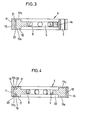
- a magnetic recording tape cartridge 1 having a pair of drive shaft insertion holes 2 defined through a top wall la and a bottom wall lb in a known manner.
- a pair of hubs 4 are rotatably mounted in the cartridge 1 with the central holes 5 aligned with the drive shaft insertion holes 2.
- a magnetic recording tape 3 is wound around the cylindrical surface of the hubs 4 in rolls with the both end portions of the recording tape engaged with engaging members (not shown) of the hubs 4 and the magnetic recording tape can be released from one hub and .taken up by another hub, running along the front surface of the cartridge 1.
- each of the hubs 4 has six projecting members 6 projected radially inward direction from the inner surface defining the central hole 5.
- a recess 7 is defined on the cylindrical surface of the hub 4 for receiving a clamping member 9 made of an elastic member so that one end of the recording tape 3 can be clamped by the clamping member 9 fitted in the recess 7.
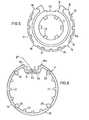
- each of the hub assembly 4 comprises an inner body 10 having rather a large thickness in an axial direction of the hub for forming the essential portion of the hub 4 and an outer ring 11 which is thin in a radial direction and fixedly fitted with the outer cylindrical surface of the inner body 10 so as to provide an outer cylindrical part of the hub assembly 4.
- the inner body 10 comprises the central hole 5 at its central part and the projecting members 6.
- a recess 13 is defined on the outer cylindrical face of the inner body 10.
- the outer ring 11 comprises a wall member 14 for defining said recess 7 and being engaged in the recess 13 ot the inner body 10 and a ring member 16 to provide the outer cylindrical surface of the hub assembly 4 with the both ends 16a connected with the both ends of the wall member 14.
- the outer cylindrical surface 15 of the ring member 16 has an accurate out-of roundness or circularity and an accurate verticality in the axial direction.
- the inner body 10 and the outer ring 11 are formed by plastic resin materials with different colors by bi-color resin molding method.
- the inner body 10 is primarily molded by an upper die and a lower die, subsequently the inner body 10 with the lower die is separated from the upper die, then the lower die with the inner body 10 is transferred directly below a second upper die for making the outer ring 11.
- the outer ring 11 is molded around the inner body 10 which is used as a core, then the inner body and the outer ring 11 are adhered by fusing their boundary surfaces.
- the inner body 10 and the outer ring 11 are molded by a similar plastic resin material such as polyacetal resin with different colors.
- plastic molding there tend to be formed sink marks and a trace of a gate near the injection gate, therefore, especially for molding the outer ring 11, the injection gate P is defined in the bottom portion of the clamping recess 7.
- the thickness of the ring portion 16 of the outer ring 11 may be 0.1 mm through 5 mm, preferably 0.5 mm through 2.5 mm and specifically 1.5 mm.
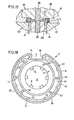
- the hub assembly 4 shown in the embodiment is provided with an arrangement for preventing a displacement between the inner body 10 and the outer ring 11 in an axial direction and a separation therebetween in a radial direction,
- stepped recesses 19 are formed extending inwardly from the outer cylindrical surface 12 at the quadrisetion points in a circumferential direction.
- annular recesses 17a are defined on both end surfaces of the inner body 10 so as to decrease friction between the end surfaces of the hub assembly 4 and slip sheets (not shown) laid on the inner surface of the cartridge, thereby fascilitating smooth running of the hub asssembly 4.
- four engaging member 20 in the form of semi-circular plate are projectingly formed in the inward direction from the inner cylindrical surface of the ring portion 16 at the positions corresponding to the stepped recesses 19, so that the engaging members 20 can be fitted in the stepped recesses 19 in a tace to face contacting manner when the inner body 10 is combined with the outer ring 11 to prevent a displacement between the the outer ring .and the inner body in a vertical direction.
- a plurality of short cylindrical slots-21 are formed in the outer circumferential edge portions of the inner body 10 in the vertical direction with a suitable interval.
- a plurality of projections 22 are formed on the inner peripheral edge portions of the outer ring 11 so that the projections 22 are strictly fitted in the corresponding slots 21, thereby preventing separation of the outer ring 11 from the inner body 10 during and after the molding process to avoid occurrence of the distortion and errors in the out-of roundness of the cylindrical surface of the outer ring 11.
- the projections 22 are constricted on the connecting portions to the inner cylindrical face of the outer ring 11, occurrence of sink mark on the outer cylindrical edge of the outer ring 11 corresponding to the projections 22 can be effectively avoided.
- a dovetail groove 23 is defined in the bottom edge portion of the recess 13 through the inner body 10 in the axial direction of the inner body 10.
- an engaging member 24 is formed on the wall member 14 which defines a bottom part of the recess 7 so that the engaging member 24 is strictly fitted in the dovetail groove 23 when the inner body 10 and the outer ring 11 are molded.
- the wall member 14 is not separated from the inner ring 11 in the radial direction.
- the outer ring 11 can be manufactured with high accuracy of out-of roundness and verticality of the annular surface thereof. Therefore, even if there occurs sink mark on the peripheral surface of the inner body 10, the effect of the sink mark does not appear on the outer cylindrical surface of the hub assembly so that accuracy of the out-of roundness and the verticality of the hub assembly can be assured. Furthermore, since the inner body 10 and the outer ring 11 have different colors, it is advantageous in a reversible recording tape cartridge as shown in the embodiment, to make it easy to recognize a relative position between the rewinding hub and the taken up hub. In addition, rotational direction of the hub assembly can easily be recognized by such different colors between the inner body 10 and the outer ring 11. Such different colors between the inner body and outer ring also increases effect of design of external appearence of the hub assembly.
- a bottom wall surface lla of the outer ring 11 which is opposite side of the recess 7 has an arcuated shape conforming to the arcuated face of the cylindrical surface of the inner body 10.
- both side walls 25 for defining the recess 7 have a large thickness in the circumferential direction so as to facilitate running of plastic resin material from the injection gate P situated at the bottom of the recess 7 towards the ring portion 16 during the molding process of the outer ring 11, thereby improving accuracy of shape of the hub assembly.
- FIG. 8 A further embodiment of the hub assembly according to the present invention is shown in Fig. 8, wherein the inner surface of the outer ring 11 and the outer surface of the inner body 10 are formed by simple cylindrical surtaces so that they are combined together in surface to surface contact relation.
- separation of the inner body and the outer ring can be prevented.
- nlso,displacerent between the inner body and the outer ring can be prevented.
- the wall surface lla of the outer ring 11 and the part of the outer surface ot the inner body 10 are made flat, so as to be combined together.
- the maximum distortion in the radial direction of the cylindrical surface of the hub assembly according to the present invention was 2.5 ⁇ m, while the maximum distortion of the conventional hub was 14 ⁇ m.
- the hub assembly according to the present invention is improved in that distortion of the cylindrical surface of the hub assembly is decreased to 1/5.6 compared with the distortion occurred in the conventional hub.
- a recording/reproducing characteristic of a magnetic recording tape cartridge using the hub assemblies according to the present invention was checked.
- the magnetic recording tape cartridge according to the present invention was mounted in a recording/reproducing apparatus, then a pair of exactly same sine wave signals of 6.3 KHz were simultaneously recorded on two tracks of the left and right channels on the magnetic recording tape respectively, checking that phase displacement does not occur between the two sine wave signals by a phase meter.
- the recording of the signals are made over the entire length of the recording tape.
- the recorded sine wave signals of the left and right channels were reproduced while the phase displacement between the both reproduced signals were measured by the phase meter so as to check the fluctuation of the recording/reproducing characteristic caused by the distortion or error of the verticality of the cylindrical surface of the hub assembly.
- the output wave forms of the reproduced signals were checked by an osciloscope or a pen recorder.
- the same measurement as described above was made on a magnetic recording tape cartridge using the conventional hub to check the phase difference between the reproduced signals of the left and right channels.
- the phase difference of the signals of the right and left channels is relatively large at the beginning and the ending of the recording tape due to the distortion in the cylindrical surface of the hub.
- the maximum value of the phase difference was 40 in the conventional recording tape cartridge, while the phase difference was 20 in the recording tape cartridge according to the present invention.
- the recording and reproducing characteristics can be effectively improved.
- Figs. 11 to 13 show the primary molding process of the inner body 10 and Figs. 14 and 16 show the secondary molding process of the outer ring 11.
- a die assembly there are provided a lower movable die 30 used for forming the lower surface of the inner body 10 and the lower surface of the outer ring 11, an upper die 35 for molding the inner body 10 and an upper die 40 for molding the outer ring 11.
- the lower movable die 30 comprises four pushing pins 26 and cores 27, 23 and 29 for forming the respective lower surfaces of the inner body 10 and the outer ring 11.
- the upper die 35 comprises four pushing pins 31 corresponding to the pushing pins 26 in the lower movable die 30 and cores 32, 33 and 34 for forming the cylindrical surface and the upper surface of the inner body 10 including the recess 7.
- the upper die 40 comprises four pushing pins 36 and cores 37, 38 and 39 for forming the outer cylindrical surface and the upper surface of the outer ring 11 including the recess 7.
- the movable die 30 is rotatable in a horizontal plane and is normally situated remote from the upper die 35 and the upper die 40 for the outer ring.
- the movable die 30 is assembled with the upper die 35 for the inner body, subsequently white plastic resin material is injected in the cavity defined by the dies 30 and 35 to mold the inner body 10.
- the pushing pins 26 are moved upwardly and the pushing pins 31 are moved downwardly to form the respective stepped faces 19 on the top and bottom faces of the inner ring 10 at the respective quadrisected points on the outer cylindrical surface portion of the inner body 10 by the end surfaces of the pushing pins 26 and 31.
- the dies 30 and 35 are separated after the inner body 10 is cooled and cured up to such a condition that the inner body can be taken out of the dies.
- the pushing pins 31 of the upper die 35 are projected downwardly so as to separate the inner body 10 with the movable die 30 from the upper die 35.
- the movable die 30 containing the inner body 10 is moved just below the upper die 40 for the outer ring 11, then the movable die 30 is assembled with the upper die 40. Subsequently, the pushing pins 26 are downwardly retracted slightly. Prior to that step, also the lower ends of the pushing pins 36 were located slightly higher than the stepped face 19. Then, the plastic resin materials of yellow color for the secondary molding are injected in the dies 30 and 40 to mold the outer ring 11. In this process, the engaging members 20 are formed in the gaps between both opposed ends of the pushing pins 26 and 36 so that the engaging members 20 are projected radially inwardly from the inside edge of the outer ring 11.
- a plurality of hub assemblies having two colors can be continuously manufactured by bicolor molding. According to the molding process as described above, the hub assemblies having the completely same configuration on both of the top side and the bottom side can be manufactured.
- a plurality of pins.41 penetrating through and projected from the movable die 30 can be used for separating the molded hub assembly from the respective upper dies 35 and 40 by using the engaging torce between the inner body 10 and the pins 41.
- the pins 41 may be tapered in such a manner that the diameter of the pins 41 becomes large in a direction of the separation of the movable die 30.
- the pin 41 may be a straight cylindrical shape.
- the hub assembly molded by the way shown in Fig. 17, a plurality of holes 42 are defined in the inner body 10 as shown in Fig. 18.
- the stepped faces 19 and the engaging members 20 connecting to the stepped face 19 may be omitted.
- the provision of the slots 21 and the projections 22 is not essential.
- through holes 43 are defined between the opposed stepped faces 19 so that the molding material can be injected in the through holes 43.
- recesses 44 also may be defined between the opposed stepped faces 19 so that the engagement between the engaging members 20 and the stepped faces 19 can be reinforced.
- poly acetal resin and acrylonitrile-butadien-stylene copolymer resin can be used.
- the movable die 30 may be moved in a linearly reciprocal manner.
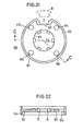
- FIG. 21 A still further embodiment of the hub assembly according to the present invention is shown in Figs. 21 through 24.
- a first molded body 110 is formed by an outer thin cylindrical member 111 for winding the magnetic recording tape, an annular plate member 112 connected with the inner cylindrical surface of the cylindrical member 111 at the center in an axial direction and six projecting members 6 projected inwardly from the inner wall 113 defining a central hole 114.
- the recess 7 for receiving the clamping member 9 is defined in the outer peripheral part of the first molded body 110 in the same way as shown in the embodiments described above.
- the cylindrical member 111 is thin having a thickness generally equal to the thickness of the annular plate member 112.
- a plurality of holes 115 are defined at an equal interval.
- Second molded members 120 are formed on both sides of the annular plate member 112 inside the cylindrical member 111 so as to enclose the annular plate member 112 by outer annular members 121 and an inner annular members 122 as shown in Figs.23 and 24.
- the second molded members 120 on both sides of the first molded body 110 are integrally connected together by connecting parts 123 formed in the holes 115 so as to prevent separation of the first molded body i10 and the second molded members 120.
- the first molded body 110 and the second molded members 120 have different colors, in other words, the outer ring portion 116 and the projecting members 6 appear to be the same color and the second molded members 120, i.e., the inner body appears to be the different color.
- the outer cylindrical surface of the second molded members 120 which corresponds to the inner body 10 is formed by a simple round surface and the outer ring portion 116 are formed by a simple annular ring.
- the bottom portion of the recess 7 of the outer ring portion 116 is formed by a flat surface 50 and wall members 51 of the second molded members 120 engaging with the flat surface 50 are also formed by a flat surface.
Landscapes
- Engineering & Computer Science (AREA)
- Manufacturing & Machinery (AREA)
- Mechanical Engineering (AREA)
- Storage Of Web-Like Or Filamentary Materials (AREA)
Applications Claiming Priority (6)
| Application Number | Priority Date | Filing Date | Title |
|---|---|---|---|
| JP133265/82 | 1982-09-01 | ||
| JP1982133265U JPS5939485U (ja) | 1982-09-01 | 1982-09-01 | テ−プカ−トリツジ |
| JP57158292A JPS5948133A (ja) | 1982-09-10 | 1982-09-10 | ハブの成形方法 |
| JP158292/82 | 1982-09-10 | ||
| JP3747283U JPS59145768U (ja) | 1983-03-17 | 1983-03-17 | テ−プカ−トリツジ用ハブ |
| JP37472/83 | 1983-03-17 |
Publications (3)
| Publication Number | Publication Date |
|---|---|
| EP0104472A2 true EP0104472A2 (de) | 1984-04-04 |
| EP0104472A3 EP0104472A3 (en) | 1986-01-29 |
| EP0104472B1 EP0104472B1 (de) | 1989-05-31 |
Family
ID=27289483
Family Applications (1)
| Application Number | Title | Priority Date | Filing Date |
|---|---|---|---|
| EP19830108516 Expired EP0104472B1 (de) | 1982-09-01 | 1983-08-30 | Aufnahmebandkassette |
Country Status (2)
| Country | Link |
|---|---|
| EP (1) | EP0104472B1 (de) |
| DE (1) | DE3379994D1 (de) |
Cited By (2)
| Publication number | Priority date | Publication date | Assignee | Title |
|---|---|---|---|---|
| GB2215305A (en) * | 1988-03-07 | 1989-09-20 | Skc Ltd | Clamping video tape to reel hub |
| WO1995023412A1 (en) * | 1994-02-25 | 1995-08-31 | Minnesota Mining And Manufacturing Company | Balanced reel hub for tape cassette reels |
Family Cites Families (7)
| Publication number | Priority date | Publication date | Assignee | Title |
|---|---|---|---|---|
| US3410500A (en) * | 1967-01-30 | 1968-11-12 | Perfection Plastics Inc | Tape reel |
| DE2114294A1 (de) * | 1970-08-10 | 1972-02-17 | Data Packaging Corp | Bandspule und Verfahren zu ihrer Herstellung |
| DE2259699A1 (de) * | 1972-12-06 | 1974-06-12 | Basf Ag | Film- oder bandspule, insbesondere fuer magnetbaender |
| JPS5428984Y2 (de) * | 1973-08-31 | 1979-09-17 | ||
| US4052020A (en) * | 1975-10-01 | 1977-10-04 | Knox Jon A | Computer tape reel |
| JPS5432494Y2 (de) * | 1977-02-18 | 1979-10-09 | ||
| DE3067176D1 (en) * | 1979-10-20 | 1984-04-26 | Hitachi Maxell | A hub for use in a magnetic recording tape cassette and a magnetic recording tape cassette comprising at least one such hub. |
-
1983
- 1983-08-30 DE DE8383108516T patent/DE3379994D1/de not_active Expired
- 1983-08-30 EP EP19830108516 patent/EP0104472B1/de not_active Expired
Cited By (3)
| Publication number | Priority date | Publication date | Assignee | Title |
|---|---|---|---|---|
| GB2215305A (en) * | 1988-03-07 | 1989-09-20 | Skc Ltd | Clamping video tape to reel hub |
| WO1995023412A1 (en) * | 1994-02-25 | 1995-08-31 | Minnesota Mining And Manufacturing Company | Balanced reel hub for tape cassette reels |
| US5472150A (en) * | 1994-02-25 | 1995-12-05 | Minnesota Mining And Manufacturing Company | Balanced reel hub for tape cassette reels |
Also Published As
| Publication number | Publication date |
|---|---|
| EP0104472B1 (de) | 1989-05-31 |
| EP0104472A3 (en) | 1986-01-29 |
| DE3379994D1 (en) | 1989-07-06 |
Similar Documents
| Publication | Publication Date | Title |
|---|---|---|
| US4672498A (en) | Tape cassette having reels with limited axial travel | |
| US4081151A (en) | Stackable winding cores for magnetic tapes | |
| US4760972A (en) | Recording tape cartridge and hub for use therein and method of making the hub | |
| KR900001104B1 (ko) | 객체로 된 테이프 안내물을 갖는 테이프 카세트 | |
| JPH0538454Y2 (de) | ||
| EP0104472A2 (de) | Aufnahmebandkassette | |
| US3243490A (en) | Method and apparatus for molding in one-piece a spool, winding core, or the like | |
| JP2622368B2 (ja) | リール心および取付けテープを有するテープクランプ | |
| JPS6140786U (ja) | テ−プリ−ル | |
| KR940004185Y1 (ko) | 테이프용 릴-허브 | |
| US5167378A (en) | Video cassette reel insert for varying tape storage capacity | |
| US4162047A (en) | Hub for use in a tape casette | |
| US4387864A (en) | Video cassette | |
| EP0188338A1 (de) | Bandführung mit Blattfedern | |
| EP0323101B1 (de) | Bandkassette mit Vorder- und Hinterklappe | |
| KR950004529B1 (ko) | 단일부품으로 된 테이프 릴, 그 테이프 카세트 및 이들의 제조방법 | |
| KR830000376Y1 (ko) | 비데오 카셋트용 테이프릴 | |
| US7887318B2 (en) | Mold assembly for molding tapered flange | |
| JP4841668B2 (ja) | テープカートリッジ用テープリールのフランジとその成形金型 | |
| CA1226062A (en) | Reel hub for a magnetic tape cassette | |
| EP0247821A2 (de) | Verfahren zum Herstellen einer Bandspule | |
| EP0247822A2 (de) | Verfahren zum Herstellen einer Bandspule | |
| JPH0127192Y2 (de) | ||
| JPH071621B2 (ja) | テープカセット及びその製造方法 | |
| JPH10275445A (ja) | 磁気テープカセット用リール |
Legal Events
| Date | Code | Title | Description |
|---|---|---|---|
| PUAI | Public reference made under article 153(3) epc to a published international application that has entered the european phase |
Free format text: ORIGINAL CODE: 0009012 |
|
| AK | Designated contracting states |
Designated state(s): DE FR GB |
|
| PUAL | Search report despatched |
Free format text: ORIGINAL CODE: 0009013 |
|
| AK | Designated contracting states |
Designated state(s): DE FR GB |
|
| 17P | Request for examination filed |
Effective date: 19860723 |
|
| 17Q | First examination report despatched |
Effective date: 19871119 |
|
| GRAA | (expected) grant |
Free format text: ORIGINAL CODE: 0009210 |
|
| AK | Designated contracting states |
Kind code of ref document: B1 Designated state(s): DE FR GB |
|
| REF | Corresponds to: |
Ref document number: 3379994 Country of ref document: DE Date of ref document: 19890706 |
|
| ET | Fr: translation filed | ||
| PLBE | No opposition filed within time limit |
Free format text: ORIGINAL CODE: 0009261 |
|
| STAA | Information on the status of an ep patent application or granted ep patent |
Free format text: STATUS: NO OPPOSITION FILED WITHIN TIME LIMIT |
|
| 26N | No opposition filed | ||
| REG | Reference to a national code |
Ref country code: GB Ref legal event code: IF02 |
|
| PGFP | Annual fee paid to national office [announced via postgrant information from national office to epo] |
Ref country code: FR Payment date: 20020808 Year of fee payment: 20 |
|
| PGFP | Annual fee paid to national office [announced via postgrant information from national office to epo] |
Ref country code: GB Payment date: 20020828 Year of fee payment: 20 |
|
| PGFP | Annual fee paid to national office [announced via postgrant information from national office to epo] |
Ref country code: DE Payment date: 20020904 Year of fee payment: 20 |
|
| PG25 | Lapsed in a contracting state [announced via postgrant information from national office to epo] |
Ref country code: GB Free format text: LAPSE BECAUSE OF EXPIRATION OF PROTECTION Effective date: 20030829 |
|
| REG | Reference to a national code |
Ref country code: GB Ref legal event code: PE20 |