EP0104418A1 - Device for the admission of detergent and rinsing water in a dental care equipment - Google Patents
Device for the admission of detergent and rinsing water in a dental care equipment Download PDFInfo
- Publication number
- EP0104418A1 EP0104418A1 EP83108233A EP83108233A EP0104418A1 EP 0104418 A1 EP0104418 A1 EP 0104418A1 EP 83108233 A EP83108233 A EP 83108233A EP 83108233 A EP83108233 A EP 83108233A EP 0104418 A1 EP0104418 A1 EP 0104418A1
- Authority
- EP
- European Patent Office
- Prior art keywords
- overflow
- valve
- shut
- water
- housing
- Prior art date
- Legal status (The legal status is an assumption and is not a legal conclusion. Google has not performed a legal analysis and makes no representation as to the accuracy of the status listed.)
- Granted
Links
Images

Classifications
-
- A—HUMAN NECESSITIES
- A61—MEDICAL OR VETERINARY SCIENCE; HYGIENE
- A61C—DENTISTRY; APPARATUS OR METHODS FOR ORAL OR DENTAL HYGIENE
- A61C1/00—Dental machines for boring or cutting ; General features of dental machines or apparatus, e.g. hand-piece design
- A61C1/0061—Air and water supply systems; Valves specially adapted therefor
- A61C1/0084—Supply units, e.g. reservoir arrangements, specially adapted pumps
-
- A—HUMAN NECESSITIES
- A61—MEDICAL OR VETERINARY SCIENCE; HYGIENE
- A61C—DENTISTRY; APPARATUS OR METHODS FOR ORAL OR DENTAL HYGIENE
- A61C19/00—Dental auxiliary appliances
Definitions
- the invention relates to a device for admitting cleaning and rinsing water into a dental treatment device, means for preventing the backflow into the supply network being provided in such a way that the water is let in with the aid of a controllable shut-off valve in a storage space which has at least one overflow outlet and in it lower region has at least one removal opening and wherein a fill level button interacts with the shut-off valve.
- the invention is intended to reduce the risk of undesirably strong movements in the storage space and to propose a device which is specifically suitable for dental treatment facilities.
- an intermediate collection container is assigned to the storage space, into which the water flows from an inlet nozzle downstream of the shut-off valve and that at least one overflow opening is provided on the intermediate collection container, from which the water flows out into the storage space.
- the liquid jet does not get directly onto the surface of the water still present in the storage room, but into the intermediate collection container.
- the valve can be switched on if necessary and switches off only once when the desired level is reached because the liquid level slowly rises. You can provide any level switch with floats or other direct electronic scanning devices.
- the storage room and intermediate collection container can have a wide variety of shapes.
- the intermediate collection container above the storage room is expediently viewed. However, it can at least partially also lie within the storage space and be surrounded by it. The design is easy and can be carried out without much additional effort.
- An intermediate collection container can also be accommodated in small spaces.
- the intermediate collection container has discharge openings as overflow openings in the region of its base and at least one overflow opening at a distance above the base. Then the water flow into the storage room is divided into several openings and a small portion can be drained slowly through the floor, while a part of the water overflows when the entire filling of the intermediate collection container is reached.
- the arrangement of the inlet nozzle in the region of the upper edge of the intermediate collection container and not at a greater distance from it prevents strong splashing even at high inlet pressure, because all splashes are caught in the intermediate collection container.
- a structurally favorable and only a little space-consuming design suitable for many applications provides that the storage space is provided in an elongated, vertically arranged, preferably circular tubular housing, which is at a distance below the inlet nozzle has an overflow connection and an overflow recess in the side wall as overflow exits and that the overflow opening of the preferably circular cylindrical intermediate collecting container is arranged on the side opposite the overflow recess of the housing and the intermediate collecting container has a wall covering the incoming water jet in the region of the overflow recess of the wall of the storage chamber, which runs at a distance from the side wall of the housing.
- the favorable location of the various necessary or sensible overflow openings prevents splash water from reaching the overflow recess of the storage space directly or almost directly from the inlet nozzle and exposing the surrounding area of the device to the risk of getting wet.
- the approximately cylindrical arrangement of the individual parts one above the other and one inside the other permits favorable flow conditions as well as manufacturing and assembly options.
- the overflow connection on the storage space can be formed with an obliquely downward-pointing pipe socket, on which an overflow hose can be plugged.
- the outlet of the check valve a sedative - has space, in which a perforated or slot-shaped basket-calming element is arranged, through which the output by the shut-off valve water flows to the inlet nozzle.
- the intermediate collection container will always have to be provided at least partially above the storage space because the water must overflow.
- Switching devices for the fill level sensor can be accommodated in this holding rod, in particular in the form of a reed contact which can be switched with magnetic forces.
- the holding rod then appropriately surrounds an annular float in which there is a permanent magnet.
- the structural design is simple and the circuit can be safely implemented.
- the holding rod and float must be equipped with stroke limit stops so that the float does not make any uncontrolled movements. In terms of assembly technology and production, it is favorable if the holding rod with the reed contact is carried by a base plate which is screwed on to the bottom of the housing with the aid of a seal using a union nut.
- the removal openings for the storage space can be provided in various ways, for example through protruding lines. Appropriately, however, several hose connecting pieces are formed in the lower part of the housing wall. These can be at the same height or at different heights, depending on the water requirements of the individual customers and what aspects need to be taken into account in the design and manufacture as well as in the case of installation.
- a commercially available magnetic shut-off valve is particularly advantageous with plug-in fastening, for which the housing can have a plug-in space that is open at the top. Assembly is made easier if the housing is designed on its circumference with a clampable clamp and clamp for the control lines.
- the housing can be produced together with other device parts or can be composed of several parts.
- a housing which is inexpensive to manufacture is suitable, which is a one-piece, elongated, tubular body with molded-on removal hose connection piece and overflow connection made of injection-molded plastic.
- the shut-off valve can be actuated in various ways. In particular, electromagnetic actuation is particularly suitable, since it also allows inexpensive switch design and fill level sensing in the small space. Further details, refinements and advantages of the invention also emerge from the following description, drawn up with reference to the drawings.
- the device 10 has an approximately circular-cylindrical or circular-tubular elongated housing 11, which at the top has an approximately square cross-section insertion space 12 for a commercially available electromagnetically operated shut-off valve 13.
- the lower end 14 is closed with a base plate 15 with the addition of a seal 16, in which a union nut 17 is screwed on, which has a central recess 18 for switch lines 19.
- the housing 11 has a substantially cylindrical interior 20, which is divided into a lower storage space 20.1 and an upper inlet and overflow space 20.2, without these being strictly separated by a wall or the like.
- the holding rod 21 protrudes from the base plate 15. This holds the intermediate collecting container 23 firmly glued on or fastened in some other way.
- the holding rod 21 has inside: a receiving space 21.1, in which a magnetically actuated contact pair 22, a so-called reed contact, is accommodated.
- the contacts are connected to the switch lines 19.
- the holding rod 21 has a stroke limiting stop 21.3 approximately at its center at a considerable distance from the base plate 15. Above from this stroke limit stop 21.3 there is an annular float 25, in which a ring magnet or another arrangement of magnets 26 for actuating the reed contact 22 is attached in a known manner and with a corresponding design.
- the float is made of a light material, such as a hollow plastic or a foam plastic, so that it can be lifted from the water surface.
- the upper stroke limitation for the float is formed by stroke limitation ribs 27 under the bottom 28 of the intermediate collection container 23.
- the intermediate collection container 23 is approximately circular-cylindrical in shape and - as can be seen in FIG. 1 - has an outer diameter which is somewhat smaller than the inner diameter of the space 20 of the housing 11, so that water can flow past the sides.
- Guide fins 31 serve to guide the water.
- the intermediate collection container 23 has an elongated shape and a length which makes up about two thirds of the storage space located below it, but a much smaller receiving volume of only a few cubic centimeters. It is namely provided with a recess 32 on one side up to somewhat below its height center, so that its outer wall 33 forms an overflow edge 34 which, together with the recess 32, represents the overflow opening.
- the recess 32 takes up about a quarter of a full circumference, so that the outer wall 33 can offer protection and guidance to the incoming water jet in the remaining three quarters.
- the intermediate collection container 23 is located in the overflow area 20.3 of the interior.
- overflow recess 40 of the storage space 20.1 which is designed as a slot machined into the side wall 11.1 or left free during the spraying process and also extends over approximately a quarter of the circumference, but on the side opposite the overflow edge 34 of the intermediate collection container 23 , so that the incoming water jet cannot immediately reach the overflow recess 40.
- Continuous drain openings 24 are formed in the bottom 28 of the intermediate collection container 23.
- an overflow connection pipe stub 41 which has an opening 42 that is open to the storage space, is led away in one piece in the housing wall - as can be seen from the figures - in one piece. It serves to properly lead water that rises too high if the level control fails, for which purpose a drain hose is plugged onto the nozzle. If this hose is clogged, a further overflow recess, namely the overflow recess 40, is provided according to the regulations, which allows water that rises further to escape into the free surrounding space.
- the inlet nozzle 45 for the water jet is located approximately in the area of the upper edge 44 of the outer wall 33 of the intermediate collection container 23. It is designed in the form of a screw-in part with an external hexagon and is screwed into the outlet port 46 of the shut-off valve 13.
- the outlet connector 46 has a calming space 47 in the form of a larger opening, which is normally used as a simple outlet connector because a hose is plugged onto its grooved outer wall.
- the inlet nozzle 45 is provided with a screw-in thread 45.1 and a calming element 45.2, which can be slit-basket-shaped or perforated-basket-shaped, so that the water is divided into different partial streams and thereby emerges calmly from the inlet nozzle 45. This has a conical nozzle mouth 45.3.
- the shut-off valve has a commercially available plug-in fastening 49 with a groove which is inserted in a latching manner over a correspondingly designed, elastically clamping wall recess 50 and its edge.
- the one switching line 19.1 leads to the one connection of the solenoid valve.
- the feed line 52 is connected to the second connection of the solenoid valve.
- the further feed line is line 19.2, which leads to reed contact 22.
- the switch lines 19 are inserted behind retaining hooks 54, which are integrally formed on the housing wall 11.1.
- a holding clamp 56 is clamped on the outside of a cylindrical part 11.2 of the housing wall. Height limits 57 are formed on the housing wall for these.
- the water connection to the supply network takes place via the inlet connection 58 of the shut-off valve 13.
- This is commercially available with a thread and a union nut 59.
- a reducer 60 is provided, which in turn has a union nut 61 and a pipe clamping ring 63 for a thin water supply pipe.
- the housing 11 is made in one piece from a suitable plastic by injection molding. The same applies to the union nut, the base plate, the holding rod, the intermediate collection container and, if applicable, the float. However, different plastics can be used.
- the housing 11 can be made of a slightly translucent or transparent plastic in order to be able to quickly identify any undesired contamination. Further fastening devices and the like can be provided. You can also provide connection options for stringing together several such devices.
- the water supply is not interrupted in any way, the water level continues to rise and the incoming water flows via the sufficiently dimensioned overflow connection pipe socket 41 to the attached hose and drain. If this should also be blocked, the water flows from the overflow recess 40 into the surroundings of the device. This ensures that water can under no circumstances step back into the solenoid valve arrangement from the storage space.
- the nozzle 45 is namely at a considerable distance of about at least 2 cm above the Lower edge / the uppermost overflow recess 40, so that a sufficient safety distance is guaranteed. Even in the event of failure, water cannot be sucked back through them.
- the water is removed by suction from the storage space 20.1 via the hose connection piece 65, here in relatively small quantities through approximately 2 mm large hoses into the individual parts of a suction arrangement to be rinsed and cleaned in a dental treatment facility.
- the device can be modified in many ways. Above all, it can be spatially and structurally adapted to the respective building conditions. It is important, however, that the water jet is not led directly into the storage room and the swimmer or other scanning device must constantly follow the movement of an unstable water surface and accordingly emit rapidly changing sound impulses that can only be detected with complex control electronics and become calm and. sensible circuit can be performed. Due to the simple measure of the intermediate collection container and the allowing the calm water jet to enter it, flutter problems of the switching and sensing device are simply avoided.
- the housing can be made larger in diameter or square or rectangular to accommodate the desired volume in the space available. It can also be adapted to the devices that may be directly attached. You can also adjust the height of the outlet openings of the hose connection piece 65 and the length of the lines connected to the respective amounts of water and suction conditions.
Landscapes
- Health & Medical Sciences (AREA)
- Oral & Maxillofacial Surgery (AREA)
- Dentistry (AREA)
- Epidemiology (AREA)
- Life Sciences & Earth Sciences (AREA)
- Animal Behavior & Ethology (AREA)
- General Health & Medical Sciences (AREA)
- Public Health (AREA)
- Veterinary Medicine (AREA)
- Engineering & Computer Science (AREA)
- Water Supply & Treatment (AREA)
- Dental Tools And Instruments Or Auxiliary Dental Instruments (AREA)
- Sanitary Device For Flush Toilet (AREA)
Abstract
Description
Die Erfindung betrifft eine Vorrichtung zum Einlassen von Reinigungs- und Spülwasser in eine zahnärztliche Behandlungseinrichtung, wobei Mittel zum Verhindern des Rückflusses ins Versorgungsnetz derart vorgesehen sind, daß das Wasser mit Hilfe eines steuerbaren Absperrventils in einen Vorratsraum eingelassen wird, der wenigstens einen Uberlaufausgang und in seinem unteren Bereich wenigstens eine Entnahmeöffnung aufweist und wobei ein Füllstandstaster mit dem Absperrventil zusammenwirkt.The invention relates to a device for admitting cleaning and rinsing water into a dental treatment device, means for preventing the backflow into the supply network being provided in such a way that the water is let in with the aid of a controllable shut-off valve in a storage space which has at least one overflow outlet and in it lower region has at least one removal opening and wherein a fill level button interacts with the shut-off valve.
Es sind die verschiedensten Vorrichtungen dieser Art in der allgemeinen Technik,beispielsweise für die Versorgung von Waschmaschinen, Geschirrspülmaschinen und dgl. bekannt. Es muß nämlich sichergestellt werden, daß beim Ausfall des Drucks im Versorgungsnetz ein Rücksaugen von verunreinigter Flüssigkeit mit Sicherheit vermieden wird. Deshalb verlangen die Vorschriften, daß eine Luftstrecke zwischen Wassereinlauf und Wasserentnahme vorgehen ist. Im Bereich der Versorgung zahnärztlicher Geräte hat man bisher nur wenige Stellen gehabt, an denen man einen direkten Wassereinlauf in eine Einrichtung gebraucht hätte. Insbesondere benötigt man jedoch eine Wasserspülung bei Sauganlagen, mittels deren aus dem Patientenmund Blut, Speichel und damit auch Bakterien angesaugt werden. Bisher wurde die Reinigung und Desinfektion dieser Sauganlagen dadurch vorgenommen, daß man mit dem Saugrohr oder Saugmundstück des Schlauches aus einem von Hand gefüllten Behältnis/und7oder Desinfektionsmittel ansaugte, um so das gesamte System zu reinigen. Erhöhte Hygieneanforderungen und das Bemühen, auch diesen Vorgang zu automatisieren, erfordern nun ein automatisches Zuführen von Reinigungs- und/oder Spülwasser unmittelbar in die Sauganlagen oder dgl. Dabei treten ungleich kompliziertere Verhältnisse bezüglich der Gefahr der Kontamination mit Blut oder Bakterien auf, als sie bei Spülmaschinen oder Waschmaschinen bestehen, zumal die räumlichen Verhältnisse für die Unterbringung einer solchen Einlaßvorrichtung andere sind als bei einer Spül- oder Waschmaschine. Es muß eine sehr kleine Vorrichtung geschaffen werden. Die Wassermengen sind sehr klein. Die Unterbringung getrennter Förderpumpen für das Wasser würde weiteren Raum beanspruchen und erhebliche Kosten verursachen. Es müssen über relativ lange Zeiten relativ kleine Mengen mit dem Unterdruck des Saugsystems angesaugt werden und im ganzen System sollte die Gefahr der Kontamination mit einzelnen Blutstropfen und dgl. und Bakterien auf ein Mindestmaß auch für längere Zeit herabgedrückt werden. Die bisherigen versuchsweise eingesetzten Vorrichtungen solcher Art hatte eine Vielzahl von praktischen Ausführungsproblemen vor allem dadurch, daß beim Einströmenlassen des Wassers in den Vorratsraum starke Bewegungen in diesem auftreten können, die ein sauberes Steuern des Füllstandes kaum möglich machten. Außerdem besteht bei derartigen Verwirbelungen im Vorratsraum die Gefahr der Kontamination der Einlaßeinrichtung mit möglicherweise in den Vorratsraum gelangten Bakterien. Demgemäß soll durch die Erfindung die Gefahr von unerwünscht starken Bewegungen im Vorratsraum gemindert und eine für zahnärztliche Behandlungseinrichtungen spezifisch geeignete Vorrichtung vorgeschlagen werden.Various devices of this type are known in general technology, for example for the supply of washing machines, dishwashers and the like. It must be ensured that if the pressure in the supply network fails, the back suction of contaminated liquid is avoided with certainty. Therefore the regulations require that there is an air gap between the water inlet and the water withdrawal. In the area of supplying dental equipment, there have only been a few places where a direct water inlet into a facility would have been needed. In particular, however, a water rinse is required in suction systems, by means of which blood, saliva and thus bacteria are sucked from the patient's mouth. Up to now, the cleaning and disinfection of these suction systems has been carried out by sucking in with the suction pipe or suction mouthpiece of the hose from a hand-filled container and / or disinfectant, so as to clean the entire system. Increased hygiene requirements and the effort to automate this process, now require an automatic supply of cleaning and / or rinsing water directly into the suction systems or the like. Incomparably more complicated conditions regarding the risk of contamination with blood or bacteria occur than they do Dishwashers or washing machines exist, especially since the spatial conditions for accommodating such an inlet device are different than in a dishwasher or washing machine. A very small device must be created. The amount of water is very small. The accommodation of separate feed pumps for the water would take up more space and incur considerable costs. Relatively small amounts have to be sucked in with the negative pressure of the suction system over a relatively long time and the risk of contamination with individual drops of blood and the like and bacteria in the entire system should be minimized even for longer periods Time to be depressed. The devices of this type which have been used on a trial basis to date have had a large number of practical implementation problems, in particular in that when the water flows into the storage space, strong movements can occur in said storage space, which hardly made it possible to control the fill level properly. In addition, with such turbulence in the storage room there is a risk of contamination of the inlet device with bacteria that may have entered the storage room. Accordingly, the invention is intended to reduce the risk of undesirably strong movements in the storage space and to propose a device which is specifically suitable for dental treatment facilities.
Erfindungsgemäß ist vorgesehen, daß zwecks Beruhigung des Flüssigkeitspiegels im Bereich des Füllstandstasters dem Vorratsraum ein Zwischensammelbehälter zugeordnet ist, in den das Wasser aus einer dem Absperrventil nachgeordneten Einlaßdüse fließt und daß wenigstens eine Uberströmöffnung am Zwischensammelbehälter vorgesehen ist, aus der das Wasser in den Vorratsraum abfließt. Nunmehr gelangt der Flüssigkeitsstrahl nicht unmittelbar auf die Oberfläche des im Vorratsraum noch vorhandenen Wassers, sondern in den Zwischensammelbehälter. Dabei kann man durch geeignete Anordnung seiner Wände,der Einstrahlrichtung und der Ausgestaltung des Einlaßstrahles ein nach den räumlichen Verhältnissen und gerätetechnischen Möglichkeiten optimales Einfließenlassen erreichen. Aus dem Zwischensammelbehälter gelangt das Wasser durch Durchlaß- oder.Überlauföffnungen entsprechender Dimensionierung beruhigt in den Vorratsraum, so daß der Flüssigkeitsspiegel langsam ansteigt oder beim Verbrauch abnimmt, ohne daß kurzzeitige Schwankungen mit Verwirbelungen an dessen Oberfläche auftreten, die einerseits zum häufigen Ein- und Ausschalten des Absperrventils führen konnten und die andererseits durch Hochspritzenlassen von Oberflächenpartikelchen das im Vorratsraum befindliche Wasser mit der Einlaßdüse in Verbindung brachten. Diese Gefahren sind jetzt vermieden. Das Ventil kann bei Bedarf eingeschaltet werden und schaltet nur einmal bei Erreichen des gewünschten Füllstandes ab, weil der Flüssigkeitsspiegel sich langsam anhebt. Dabei kann man beliebige Füllstandstaster mit Schwimmern oder sonstigen unmittelbaren elektronischen Abtasteinrichtungen vorsehen. Vorratsraum und Zwischensammelbehälter können die verschiedensten Formen aufweisen. Zweckmäßig wird der Zwischensammelbehälter über dem Vorratsraum angesehen. Er kann jedoch wenigstens teilweise auch innerhalb des Vorratsraumes liegen und von diesem umgeben sein. Die konstruktive Ausführung ist leicht und ohne großen Zusatzaufwand ausführbar. Auch bei kleinen Raumverhältnissen kann ein Zwischensammelbehälter untergebracht werden.According to the invention, for the purpose of calming the liquid level in the area of the fill level sensor, an intermediate collection container is assigned to the storage space, into which the water flows from an inlet nozzle downstream of the shut-off valve and that at least one overflow opening is provided on the intermediate collection container, from which the water flows out into the storage space. Now the liquid jet does not get directly onto the surface of the water still present in the storage room, but into the intermediate collection container. In this case, by means of a suitable arrangement of its walls, the direction of radiation and the configuration of the inlet jet, it is possible to achieve an optimal inflow in accordance with the spatial conditions and technical possibilities. From the intermediate collection container, the water passes through passage or overflow openings of appropriate dimensions soothes into the storage space, so that the liquid level rises slowly or decreases in consumption without short-term fluctuations with eddies on its surface, which on the one hand cause frequent switching on and off of the Could lead shutoff valve and the other hand by spraying high Surface particles brought the water in the storage space into connection with the inlet nozzle. These dangers have now been avoided. The valve can be switched on if necessary and switches off only once when the desired level is reached because the liquid level slowly rises. You can provide any level switch with floats or other direct electronic scanning devices. The storage room and intermediate collection container can have a wide variety of shapes. The intermediate collection container above the storage room is expediently viewed. However, it can at least partially also lie within the storage space and be surrounded by it. The design is easy and can be carried out without much additional effort. An intermediate collection container can also be accommodated in small spaces.
Zweckmäßig ist es, wenn der Zwischensammelbehälter als Überströmöffhungen im Bereich seines Bodens Ablaßöffnungen und im Abstand über dem Boden wenigstens eine Überlauföffnung aufweist. Dann wird der Wasserstrom in den Vorratsraum auf mehrere öffnungen verteilt und durch den Boden kann.ständig ein kleiner Anteil langsam abgelassen werden, während bei Erreichen der gesamten Füllung des Zwischensammelbehälters ein Teil des Wassers überläuft. Durch die Anordnung der Einlaßdüse im Bereich des oberen Randes des Zwischensammelbehälters und nicht in größerem Abstand davon wird ein starkes Spritzen auch bei hohem Einlaßdruck vermieden, weil alle Spritzer im Zwischensammelbehälter aufgefangen werden.It is expedient if the intermediate collection container has discharge openings as overflow openings in the region of its base and at least one overflow opening at a distance above the base. Then the water flow into the storage room is divided into several openings and a small portion can be drained slowly through the floor, while a part of the water overflows when the entire filling of the intermediate collection container is reached. The arrangement of the inlet nozzle in the region of the upper edge of the intermediate collection container and not at a greater distance from it prevents strong splashing even at high inlet pressure, because all splashes are caught in the intermediate collection container.
Eine konstruktiv günstige und nur wenig Raum beanspruchende für viele Einsatzfälle geeignete Ausführung sieht vor, daß der Vorratsraum in einem langgestreckten, vertikal angeordneten, vorzugsweise kreisröhrenförmigen Gehäuse vorgesehen ist, welches im Abstand unter der Einlaßdüse in der Seitenwand als Überlaufausgänge einen Überlaufanschluß und eine Überlaufausnehmung aufweist und daß die Überlauföffnung des vorzugsweise kreiszylinderförmigen Zwischensammelbehälters auf der der Überlaufausnehmung des Gehäuses gegenüberliegenden Seite angeordnet ist und der Zwischensammelbehälter im Bereich der überlaufausnehmung der Wand des Gehäuses des Vorratsraumes eine den eintretenden Wasserstrahl abdeckende Wand aufweist, die im Abstand von der Seiten wand des Gehäuses verläuft. Durch die günstige Lage der verschiedenen notwendigen oder sinnvollen Überlauföffnungen wird vermieden, daß Spritzwasser direkt oder nahezu unmittelbar von der Einlaßdüse zur Überlaufausnehmung des Vorratsraumes gelangt und so der Umgebungssraum der Vorrichtung der Gefahr des Naßwerdens ausgesetzt ist. Die etwa zylindrische Übereinander-und Ineinander-Anordnung der einzelnen Teile gestattet günstige Strömungsverhältnisse sowie Herstellungs- und Montagemöglichkeiten.A structurally favorable and only a little space-consuming design suitable for many applications provides that the storage space is provided in an elongated, vertically arranged, preferably circular tubular housing, which is at a distance below the inlet nozzle has an overflow connection and an overflow recess in the side wall as overflow exits and that the overflow opening of the preferably circular cylindrical intermediate collecting container is arranged on the side opposite the overflow recess of the housing and the intermediate collecting container has a wall covering the incoming water jet in the region of the overflow recess of the wall of the storage chamber, which runs at a distance from the side wall of the housing. The favorable location of the various necessary or sensible overflow openings prevents splash water from reaching the overflow recess of the storage space directly or almost directly from the inlet nozzle and exposing the surrounding area of the device to the risk of getting wet. The approximately cylindrical arrangement of the individual parts one above the other and one inside the other permits favorable flow conditions as well as manufacturing and assembly options.
Der Überlaufanschluß am Vorratsraum kann mit einem schräg nach unten weisenden Rohrstutzen gebildet sein, auf welchen ein Überlaufschlauch steckbar ist. So kann in den Vorratsraum unbeabsichtigt einlaufendes Wasser mit Sicherheit einfach zum Abfluß geleitet werden, ohne daß die Gefahr des Anstieg des Wasserspiegels oder die Gefahr des Gelangens von Spritzer aus dem Vorratswasser an die Düse bestünde.The overflow connection on the storage space can be formed with an obliquely downward-pointing pipe socket, on which an overflow hose can be plugged. Thus, inadvertently entering the storage space, water can safely be simply led to the drain without the risk of rising water levels or the risk of splashes from the storage water reaching the nozzle.
Auch der Gestaltung des Wassereinlaßstromes ist Beachtung zu widmen, weil auch dadurch die Verwirbelungsverhältnisse in der gesamten Vorrichtung stark beeinflußt werden. Demgemäß sieht eine weitere Ausgestaltung der Erfindung vor, daß der Auslaßstutzen des Absperrventils einen Beruhigungs- raum aufweist, in dem ein loch- oder schlitz-korb-förmiges Beruhigungselement angeordnet ist, durch welches das vom Absperrventil abgegebene Wasser zur Einlaßdüse fließt. Man kann so zwar ein handelsübliches Absperrventil am Einlaß verwenden, diesem jedoch eine besondere Düsenanordnung zuordnen, die einen gleichmäßigen und gut gebündelten Wasserstrom austreten läßt.Attention should also be paid to the design of the water inlet flow, because this also strongly influences the swirl conditions in the entire device. Accordingly, a further embodiment of the invention, that the outlet of the check valve a sedative - has space, in which a perforated or slot-shaped basket-calming element is arranged, through which the output by the shut-off valve water flows to the inlet nozzle. You can use a commercially available shut-off valve at the inlet use, but assign this to a special nozzle arrangement that allows an even and well-concentrated water flow to emerge.
Den Zwischensammelbehälter wird man stets wenigstens teilweise oberhalb des Vorratsraumes vorsehen müssen, weil das Wasser überlaufen muß. Man kann ihn konstruktiv einfach auf einem Haltestab anordnen, der vom Boden des Vorratsraumes aufragt. In diesem Haltestab lassen sich günstig Schalteinrichtungen für den Füllstandstaster unterbringen und zwar insbesondere in Form eines mit magnetischen Kräften schaltbaren Reed-Kontaktes. Den Haltestab umgibt dann zweckmäßig ein ringförmiger Schwimmer, in dem sich ein Dauermagnet befindet. Die konstruktive Ausgestaltung ist einfach unddie Schaltung sicher möglich. Haltestab und Schwimmer sind mit Hubbegrenzungsanschläge auszustatten, um den Schwimmer keine unkontrollierten Bewegungen ausführen zu lassen. Montagetechnisch und für die Herstellung ist es günstig, wenn der Haltestab mit dem Reed-Kontakt von einer Bodenplatte getragen ist, welche mit Hilfe einer Überwurfmutter unten am Gehäuse unter Beilage einer Dichtung angeschraubt ist.The intermediate collection container will always have to be provided at least partially above the storage space because the water must overflow. One can constructively arrange it on a holding rod which rises from the floor of the storage room. Switching devices for the fill level sensor can be accommodated in this holding rod, in particular in the form of a reed contact which can be switched with magnetic forces. The holding rod then appropriately surrounds an annular float in which there is a permanent magnet. The structural design is simple and the circuit can be safely implemented. The holding rod and float must be equipped with stroke limit stops so that the float does not make any uncontrolled movements. In terms of assembly technology and production, it is favorable if the holding rod with the reed contact is carried by a base plate which is screwed on to the bottom of the housing with the aid of a seal using a union nut.
Die Entnahmeöffnungen für den Vorratsraum können in verschiedener Weise vorgesehen sein, beispielsweise durch hineinragende Leitungen. Zweckmäßig bildet man jedoch in der Gehäusewand im unteren Bereich mehrere Schlauchanschlußstutzen aus. Diese können in gleicher Höhe oder auch in unterschiedlichen Höhen-liegen, je nachdem, welchen Wasserbedarf die einzelnen Abnehmer aufweisen und welche Gesichtspunkte bei Konstruktion und Herstellung sowie im Einbaufall zu berücksichtigen sind.The removal openings for the storage space can be provided in various ways, for example through protruding lines. Appropriately, however, several hose connecting pieces are formed in the lower part of the housing wall. These can be at the same height or at different heights, depending on the water requirements of the individual customers and what aspects need to be taken into account in the design and manufacture as well as in the case of installation.
Für die Befestigung des-Absperrventils gibt es die verschiedensten Lösungen je nach Art des Ventils. Besonders vorteilhaft ist ein handelsübliches Magnetabsperrventil mit Steckbefestigurig,für welches das Gehäuse im oberen Bereich einen nach oben offenen Einsteckraum aufweisen kann. Die Montage wird erleichert, wenn das Gehäuse an seinem Umfang mit einer Hubbegrenzungen aufweisenden klemmbaren Halteschelle und Haltehaken für die Steuerleitungen ausgebildet ist. Das Gehäuse kann je nach dem Einsatzzweck mit weiteren Vorrichtungsteilen gemeinsam hergestellt oder aus mehreren Teilen zusammengesetzt sein. Für viele Einsatzfälle eignet sich jedoch ein herstellungsmäßig preiswertes Gehäuse, welches ein einstückiger, langgestreckter, rohrförmiger Körper mit angeformten Entnahme-Schlauchanschlußstutzen und Uberlaufanschluß aus spritzgegoßenem Kunststoff ist. Die Betätigung des Absperrventils kann auf verschiedene Weise erfolgen. Insbesondere eignet sich eine elektromagnetische Betätigung zumal diese bei den kleinen Raumverhältnissen auch günstige Schalterausbildung und Füllstandsabtastung gestattet. Weitere Einzelheiten, Ausgestaltungen und Vorteile der Erfindung ergeben sich auch aus dem nachfolgenden, anhand der Zeichnungen abgefaßten Beschreibungsteil.There are various solutions for fastening the shut-off valve depending on the type of valve. A commercially available magnetic shut-off valve is particularly advantageous with plug-in fastening, for which the housing can have a plug-in space that is open at the top. Assembly is made easier if the housing is designed on its circumference with a clampable clamp and clamp for the control lines. Depending on the intended use, the housing can be produced together with other device parts or can be composed of several parts. For many applications, however, a housing which is inexpensive to manufacture is suitable, which is a one-piece, elongated, tubular body with molded-on removal hose connection piece and overflow connection made of injection-molded plastic. The shut-off valve can be actuated in various ways. In particular, electromagnetic actuation is particularly suitable, since it also allows inexpensive switch design and fill level sensing in the small space. Further details, refinements and advantages of the invention also emerge from the following description, drawn up with reference to the drawings.
Ein Ausführungsbeispiel der Erfindung wird nachfolgend anhand der Zeichnungen näher erläutert und beschrieben.An embodiment of the invention is explained and described in more detail below with reference to the drawings.
Es zeigen:
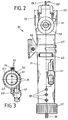
- Fig. 1 einen Vertikalschnitt längs der Linie 1-1 in Fig. 2 durch die Vorrichtung;
- Fig. 2 eine Ansicht von rechts auf die Vorrichtung nach Fig. 1;
- Fig. 3 einen Querschnitt längs der Linie 3-3 in Fig. 1.
- Figure 1 is a vertical section along line 1-1 in Figure 2 through the device.
- Fig. 2 is a right view of the device of Fig. 1;
- 3 shows a cross section along the line 3-3 in FIG. 1.
Die Vorrichtung 10 hat ein etwa kreiszylinderförmiges oder kreisrohrförmiges langgestrecktes Gehäuse 11, welches oben einen im Querschnitt etwa quadratischen Einsteckraum 12 für ein handelsübliches elektromagnetisch betätigtes Absperrventil 13 aufweist. Das untere Ende 14 ist mit einer Bodenplatte 15 unter Beilage einer Dichtung 16 verschlossen, in dem eine überwurfmutter 17 aufgeschraubt ist, die eine Mittelausnehmung 18 für Schalterleitungen 19 aufweist. Das Gehäuse 11 hat einen im wesentlichen zylindrischen Innenraum 20, der sich in einen.unteren Vorratsraum 20.1 und einen oberen Eintritts- und Überlaufraum 20.2 gliedert, ohne daß diese streng durch eine Wand oder dergleichen getrennt wären.The
Von der Bodenplatte 15 ragt ein im Innern hohler Haltestab 21 auf. Dieser trägt fest aufgeklebt oder in sonstiger Weise befestigt den Zwischensammelbehälter 23. Der Haltestab 21 weist im:Innern einen Aufnahmeraum 21.1 auf, in dem ein magnetisch zu betätigendes Kontaktpaar 22, ein sogenannter Reed-Kontakt untergebracht ist. Die Kontakte sind mit den Schalterleitungen 19 verbunden. Der Haltestab 21 hat etwa auf seiner Mitte in einem beträchtlichen Abstand von der Bodenplatte 15 einen Hubbegrenzungsanschlag 21.3. Oberhalb von diesem Hubbegrenzungsanschlag 21.3 befindet sich ein ringförmiger Schwimmer 25, in dem ein Ringmagnet oder eine sonstige Anordnung von Magneten 26 für die Betätigung des Reed-Kontaktes 22 in bekannter Weise und mit entsprechender Auslegung angebracht ist. Der Schwimmer besteht aus leichtem Werkstoff, wie einem hohlen Kunststoff oder einem Schaumkunststoff, so daß er von der Wasseroberfläche angehoben werden kann. Die obere Hubbegrenzung für den Schwimmer wird von Hubbegrenzungsrippen 27 unter dem Boden 28 des Zwischensammelbehälters 23 gebildet. Am Boden 28 ist ferner ein Befestigungshalter 29 für den Endzapfen 30 des Haltestabes 15 vorgesehen, wo beispielsweise eine Kleb- oder Schweißverbindung angewendet wird. Der Zwischensammelbehälter 23 ist etwa kreiszylinderförmig gestaltet und hat - wie aus Fig. 1 ersichtlich - einen Außendurchmesser der etwas geringer als der Innendurchmesser des Raumes 20 des Gehäuses 11 ist, so daß Wasser an den Seiten vorbeifließen kann. Leitflossen 31 dienen der Wasserführung. Der Zwischensammelbehälter 23 hat eine langgestreckte Form und eine Länge, die etwa zwei Drittel des unter ihm befindlichen Vorratsraumes ausmacht, jedoch ein wesentlich geringeres Aufnahmevolumen von nur wenigen Kubikzentimetern. Er ist nämlich bis etwas unterhalb seiner Höhenmitte einseitig mit einer Ausnehmung 32 versehen, so daß seine Außenwand 33 eine Überlaufkante 34 bildet, die zusammen mit der Ausnehmung 32 die Überlauföffnung darstellt. Die Ausnehmung 32 nimmt etwa ein Viertel eines vollen Umfanges ein, so daß die Außenwand 33 im übrigen Dreiviertel dem eintretenden Wasserstrahl Schutz und Führung bieten kann. Der Zwischensammelbehälter 23 befindet sich im Überlaufbereich 20.3 des Innenraumes. Etwas oberhalb der überlaufkante 34 liegt nämlich die überlaufausnehmung 40 des Vorratsraumes 20.1, die als in die Seitenwand 11.1 eingearbeiteter oder beim Spritzvorgang freigebliebener Schlitz gestaltet ist und sich ebenfalls über etwa ein Viertel des Umfanges erstreckt, jedoch auf der der überlaufkante 34 des Zwischensammelbehälters 23 gegenüberliegenden Seite, so daß der eintretende Wasserstrahl nicht sofort zur Überlaufausnehmung 40 gelangen kann. Im Boden 28 des Zwischensammelbehälters 23 sind durchgehende Ablaßöffnungen 24 ausgebildet.An internally hollow holding
Etwas unterhalb der Uberlaufausnehmung 40 ist in der Gehäusewand - wie aus den Figuren ersichtlich - einstückig ein Überlaufanschlußrohrstutzen 41 schräg nach unten weggeführt, der eine zum Vorratsraum offene Durchtrittsöffnung 42 aufweist. Er dient dazu, beim Versagen der Füllstandssteuerung zu hoch steigendes Wasser ordnungsgemäß zu einem Abfluß zu führen, wozu ein Abflußschlauch auf den Stutzen gesteckt wird. Sollte dieser Schlauch verstopft sein, so ist gemäß den Vorschriften eine weitere Überlaufausnehmung, nämlich die Überlaufausnehmung 40 vorgesehen, die noch weiter ansteigendes Wasser in den freien Umgebungsraum austreten läßt.Slightly below the
Etwa im Bereich der Oberkante 44 der Außenwand 33 des Zwischensammelbehälters 23 liegt die Einlaßdüse 45 für den Wasserstrahl. Sie ist in Form eines Einschraubteiles mit einem Außensechskant gestaltet und ist in den Ausgangsstutzen 46 des Absperrventils 13 eingeschraubt. Der Auslaßstutzen 46 hat im Innern einen Beruhigungsraum 47 in Form einer größeren öffnung, die normalerweise als einfacher Auslaßstutzen verwendet wird, weil auf seine gerillte Außenwand ein Schlauch gesteckt wird. Hier ist jedoch die Einlaßdüse 45 mit einem Einschraubgewinde 45.1 und einem Beruhigungselement 45.2 versehen,.welches schlitz-korbförmig oder auch loch-korbförmig gestaltet sein kann, so daß das Wasser in verschiedene Teilströme aufgeteilt wird und dadurch beruhigt aus der Einlaßdüse 45 austritt. Diese hat einen konischen Düsenmund 45.3.The
Das Absperrventil hat eine handelsübliche Steckbefestigung 49 mit einer Nut, die über eine entsprechend gestaltete elastisch klemmende Wandausnehmung 50 und ihren Rand rastend gesteckt wird. Die eine Schaltleitung 19.1 führt zu dem einen Anschluß des Magnetventils. Die Zuführleitung 52 ist am zweiten Anschluß des Magnetventils-angeschlossen. Die weitere Zuführleitung ist die Leitung 19.2, die zum Reed-Kontakt 22 führt. Die Schalterleitungen 19 sind hinter Haltehaken 54, welche einstückig an der Gehäusewand 11.1 ausgebildet sind, gesteckt.The shut-off valve has a commercially available plug-in
Auf einen zylindrischen Teil 11.2 der Gehäusewand ist außen eine Halteschelle 56 geklemmt. Für diese sind Höhenbegrenzungen 57 an der Gehäusewand ausgebildet.A holding
Der Wasseranschluß ans Versorgungsnetz erfolgt über den Einlaßstutzen 58 des Absperrventils 13. Dieser ist handelsüblich mit einem Gewinde und einer'Uberwurfmutter 59 ausgestattet. Unter Beilage von Dichtung und Filter ist ein Reduzierstück 60 vorgesehen, welches seinerseits eine überwurfmutter 61 und einen Rohrklemmring 63 für ein dünnes Wasserzuführrohr aufweist.The water connection to the supply network takes place via the
Im unteren Bereich der Wand 11.1 des Vorratsraumes 20.1 sind übereinanderliegend drei Schlauchanschlußstutzen 65 mit Entnahmeöffnungen vorgesehen. Diese sind mit einer durchgehenden Öffnung oder ggf. mit einer im Durchmesser verringerten Wandöffnung ausgestattet sein, so daß die Saugmengen durch Drosselwirkung bestimmt werden können. Das Gehäuse 11 ist einstückig aus einem geeigneten Kunststoff im Spritzgußverfahren hergestellt. Gleiches gilt für die Überwurfmutter, die Bodenplatte, den Haltestab, den Zwischensammelbehälter und ggf. den Schwimmer. Es können jedoch unterschiedliche Kunststoffe verwendet sein. Das Gehäuse 11 kann aus einem leicht durchscheinenden oder durchsichtigen Kunststoff gefertigt sein, um evtl. unerwünschte Verunreinigung schnell erkennen zu können. Weitere Befestigungseinrichtungen und dgl. können vorgesehen sein. Auch kann man Verbindungsmöglichkeiten für das Aneinanderreihen mehrerer solcher Vorrichtungen vorsehen.In the lower area of the wall 11.1 of the storage space 20.1, three
Die Arbeitsweise der beschriebenen Vorrichtung ist folgende:
- Es soll sichergestellt werden, daß durch die Schlauchanschlußstutzen 65 an eine zahnärztliche Behandlungsvorrichtung oder dgl. abgegebenes Wasser nicht beim Ausfallen des Drucks in der Netzversorgungsleitung wieder durch
den Einlaßstutzen 58 rückwärts ins Netz gelangt und dadurch Verunreinigungen und Bakterien in das öffentliche Wassernetz gelangen. Wenn eine Wasserzufuhr gewünscht wird, werden die Leitungen19.2 und 52 unter Spannung gesetzt.Wenn der Schwimmer 25 unten liegt, ist der Reed-Kontakt 22 geschlossen und das magnetisch betätigte Absperrventil 13 öffnet, Wasser gelangtdurch den Einlaßstutzen 58zum Ausgangsstutzen 46. Inseinem Beruhigungsraum 47 fließt es in das Beruhigungselement 45.2 und als beruhigter Strahl aus der Einlaßdüse 45 heraus in einem relativ kleinen und ruhigen Strahl zwischen der Außenwand 33 in den Zwischensammelbehälter 23. Evtl. spritzendes Wasser kann nicht indie überlaufausnehmung 40 gelangen. Es fließt vom Innenraum 23.4 durch dieAblaßöffnungen 24 im Boden 28 und ggf. über dieÜberlaufkante 34 in dem Ringraum zwischen derWand 33 des Zwischensammelbehälters 23 und der Wand 11.1 desGehäuses 11 in den Vorratsraum 20.1. Der Wasserstrahl trifft allenfalls auf den Boden 28 des Zwischensammelbehälters 23 oder auf dessen Wasserfläche.
- It is to be ensured that water supplied through the
hose connection piece 65 to a dental treatment device or the like does not get back into the network through theinlet connection 58 when the pressure in the mains supply line fails and thereby contaminants and bacteria get into the public water network. When a If water supply is desired, lines 19.2 and 52 are energized. When thefloat 25 is at the bottom, thereed contact 22 is closed and the magnetically operated shut-offvalve 13 opens, water passes through theinlet connection 58 to theoutlet connection 46. In its calmingchamber 47, it flows into the calming element 45.2 and as a calming jet from theinlet nozzle 45 out in a relatively small and quiet jet between theouter wall 33 into the intermediate collection container 23. Splashing water cannot get into theoverflow recess 40. It flows from the interior 23.4 through thedrain openings 24 in the bottom 28 and possibly over theoverflow edge 34 in the annular space between thewall 33 of the intermediate collection container 23 and the wall 11.1 of thehousing 11 into the storage space 20.1. The water jet strikes the bottom 28 of the intermediate collection container 23 or the water surface thereof.
Er trifft jedoch nicht auf die Wasserfläche im Vorratsraum 20.1, so daß diese beruhigt ansteigt und folglich flatterfrei den Schwimmer 25 anhebt. Solange der Schwimmer 25 nicht angehoben ist, sind infolge der Magnetkräfte des Magneten 26 die Reed-Kontakte 22 geschlossen und der Magnet des Absperrventils 13 wird gespeist. Steigt nun der Flüssigkeitsspiegel an, so wird der Schwimmer 25 und mit ihm der Magnet 26 angehoben bis zu einer Höhe, in der der Vorratsraum 20.1 ausreichend gefüllt ist. Dann lösen sich die Reed-Kontakte und das Magnetventil wird von der Speisespannung gelöst und schaltet folglich die Wasserzufuhr ab. Ggf. kann der Schwimmer bis an die Hubbegrenzungsrippen 27 anstoßen und ist so in seiner Bewegung gehemmt. Sollte auf irgendeine Weise die Wasserzufuhr nicht unterbrochen werden, so steigt der Wasserspiegel weiter an und das zulaufende Wasser fließt über den ausreichend dimensionierten Überlaufanschlußrohrstutzen 41 zu dem aufgesteckten Schlauch und Ablauf. Sollte auch dieser verstopft sein, so gelangt das Wasser aus der Uberlaufausnehmung 40 in den Umgebungsraum der Vorrichtung. So ist gesichert, daß auf keinen Fall Wasser aus dem Vorratsraum zurück in die Magnetventilanordnung treten kann. Die Düse 45 liegt nämlich in beträchtlichem Abstand von etwa mindestens 2 cm oberhalb der Unterkante/der obersten Uberlaufausnehmung 40, so daß ein ausreichender Sicherheitsabstand gewährleistet ist. Es kann auch im Versagensfalle kein Wasser durch diese rückwärts gesaugt werden.However, it does not hit the water surface in the storage space 20.1, so that it rises calmly and consequently raises the
Aus dem Vorratsraum 20.1 wird über die Schlauchanschlußstutzen 65 das Wasser durch Saugkraft entnommen, hier in relativ kleinen Mengen durch etwa 2 mm große Schläuche in die einzelnen Teile einer zu spülenden und zu reinigenden Sauganordnung einer zahnärztlichen Behandlungseinrichtung.The water is removed by suction from the storage space 20.1 via the
Die Vorrichtung kann in mancherlei Weise abgewandelt werden. Sie kann vor allem räumlich konstruktiv den jeweiligen Baubedingungen angepaßt werden. Wichtig ist jedoch, daß der Wasserstrahl nicht direkt in den Vorratsraum geleitet wird und dadurch der.Schwimmer oder eine sonstige Abtasteinrichtung ständig der Bewegung einer unruhigen Wasseroberfläche folgen müssen und entsprechend schnell wechselnde Schallimpulse abgeben, die nur mit einer aufwendigen Regelelektronik zu erfassen und zu einer ruhigen und .sinnvollen Schaltung geführt werden können. Durch die einfache Maßnahme des Zwischensammelbehälters und des Eintretenlassens des beruhigten Wasserstrahls in diesen sind Flatterprobleme der Schalt- und Tasteinrichtung einfach vermieden. Das Gehäuse kann im Durchmesser größer oder auch quadratisch oder rechteckig gestaltet werden, um das erwünschte Volumen in dem zur Verfügung stehenden Raum unterzubringen. Es kann auch den evtl. direkt anzubauenden Geräten angepaßt sein. Auch kann man die Höhenlage der Auslaßöffnungen der Schlauchanschlußstutzen 65 und die Länge der daran anschließenden Leitungen auf die jeweiligen Wassermengen und Saugbedingungen abstimmen.The device can be modified in many ways. Above all, it can be spatially and structurally adapted to the respective building conditions. It is important, however, that the water jet is not led directly into the storage room and the swimmer or other scanning device must constantly follow the movement of an unstable water surface and accordingly emit rapidly changing sound impulses that can only be detected with complex control electronics and become calm and. sensible circuit can be performed. Due to the simple measure of the intermediate collection container and the allowing the calm water jet to enter it, flutter problems of the switching and sensing device are simply avoided. The housing can be made larger in diameter or square or rectangular to accommodate the desired volume in the space available. It can also be adapted to the devices that may be directly attached. You can also adjust the height of the outlet openings of the
- 10 Vorrichtung10 device
- 11 Gehäuse11 housing
- 11.1 Seitenwand11.1 side wall
- 11.2 zylindrischer Teil11.2 cylindrical part
- 12 Einsteckraum12 insertion space
- 13 Absperrventil13 shut-off valve
- 14 unteres Ende14 bottom end
- 15 Bodenplatte15 base plate
- 16 Dichtung16 seal
- 17 Überwurfmutter17 union nut
- 18 Mittelausnehmung18 central recess
- 19 Schalterleitung19 switch line
- 19.1 Schaltleitung19.1 Switch line
- 19.2 Leitung19.2 Management
- 20 Innenraum20 interior
- 20.1 Vorratsraum20.1 pantry
- 20.2 Eintritts- und Uberlaufraum20.2 Entry and overflow space
- 20.3 Überlaufbereich20.3 Overflow area
- 21 Haltestab21 holding bar
- 21.1 Aufnahmeraum21.1 Recording room
- 21.3 Hubbegrenzungsanschlag21.3 Stroke limit stop
- 22 Kontaktpaar/ Reed-Kontakt22 Contact pair / reed contact
- 23 Zwischensammelbehälter23 intermediate collection container
- 23.4 Innenraum23.4 interior
- 24 Ablaßöffnung24 drain opening
- 25 Schwimmer25 swimmers
- 26 Magnet26 magnet
- 27 Hubbegrenzungsrippe27 stroke limiting rib
- 28 Boden28 bottom
- 29 Befestigungshalter29 mounting bracket
- 30 Endzapfen30 end pins
- 31 Leitflossen31 guide fins
- 32 Ausnehmung32 recess
- 33 Außenwand33 outer wall
- 34 Uberlaufkante34 overflow edge
- 40 Uberlaufausnehmung40 overflow recess
- 40.1 Unterkante40.1 lower edge
- 41 Uberlaufanschlußrohrstutzen41 Overflow connection pipe socket
- 42 Durchtrittsöffnung42 passage opening
- 44 Oberkante44 top edge
- 45 Einlaßdüse45 inlet nozzle
- 45.1 Einschraubgewinde45.1 screw-in thread
- 45.2 Beruhigungselement45.2 Calming element
- 45.3 Düsenmund45.3 Nozzle mouth
- 46 Ausgangsstutzen46 outlet connection
- 47 Beruhigungsraum47 relaxation room
- 49 Steckbefestigung49 plug-in fastening
- 50 Wandausnehmung50 wall recess
- 52 Zuführleitung52 supply line
- 54 Haltehaken54 retaining hooks
- 56 Halteschelle56 clamp
- 57 Höhenbegrenzung57 height limitation
- 58 Einlaßstutzen58 inlet connection
- 59 Überwurfmutter59 union nut
- 60 Reduzierstück60 reducer
- 61 Überwurfmutter61 union nut
- 63 Rohrklemmring63 Pipe clamp ring
- 65 Schlauchanschlußstutzen65 hose connector
Claims (15)
daß zwecks Beruhigung des Flüssigkeitsspiegels im Bereich des Füllstandstasters (22, 25, 26) dem Vorratsraum (20.1) ein Zwischensammelbehälter (23) zugeordnet ist, in den das Wasser aus einer dem Absperrventil (13) nachgeordneten Einlaßdüse (45) fließt und daß wenigstens eine Überströmöffnung(24, 34) am Zwischensammelbehälter (23) vorgesehen ist, aus der das-Wasser in den Vorratsraum (20.1) abfließt.1. Device (10) for admitting cleaning and / or rinsing water into a dental treatment facility, wherein means for preventing the backflow into the supply network are provided such that the water is admitted into a storage room (20.1) with the aid of a controllable shut-off valve (13) which has at least one overflow outlet (40, 41) and in its lower area at least one removal opening (65) and wherein a fill level button (22, 25, 26) interacts with the shut-off valve (13), characterized in that
that for the purpose of calming the liquid level in the area of the level sensor (22, 25, 26) the storage space (20.1) is assigned an intermediate collection container (23) into which the water flows from an inlet nozzle (45) downstream of the shut-off valve (13) and that at least one Overflow opening (24, 34) is provided on the intermediate collection container (23), from which the water flows into the storage space (20.1).
dadurch gekennzeichnet ,
daß der Zwischensammelbehälter (23) als Uberströmöffnungen im Bereich seines Bodens (28) Ablaßöffnungen(24) und im Abstand über dem Boden (28) wenigstens eine Überlauföffnung (Überlaufkante 34) aufweist.2. Device according to claim 1,
characterized ,
that the intermediate collecting container (23) has overflow openings in the region of its bottom (28), outlet openings (24) and at least one overflow opening (overflow edge 34) at a distance above the bottom (28).
dadurch gekennzeichnet ,
daß das Absperrventil (13) einen Ausgangsstutzen (46) aufweist, an dem die Einlaßdüse (45) für den Zwischensammelbehälter (23) ausgebildet ist, die im Bereich des oberen Randes (44) des Zwischensammelbehälters(23) liegt.3. Device according to claim 1,
characterized ,
that the shut-off valve (13) has an outlet port (46) on which the inlet nozzle (45) for the intermediate collection container (23) is formed, which lies in the region of the upper edge (44) of the intermediate collection container (23).
dadurch gekennzeichnet ,
daß der Vorratsraum (20.1) in einem langgestreckten, vertikal angeordneten, vorzugsweise kreisröhrenförmigen Gehäuse (11) vorgesehen ist, welches im Abstand unter der Einlaßdüse (45) in der Seitenwand (11.1) als Überlaufausgänge einen Überlaufanschluß (41) und eine Uberlaufausnehmung (40) aufweist und daß die Überlauföffnung (32, 34) des vorzugsweise kreiszylinderförmigen Zwischensammelbehälters (23) auf der der Überlaufausnehmung (40) des Gehäuses (11) gegenüberliegenden Seite angeordnet ist, und der Zwischensammelbehälter (23) im Bereich der Überlaufausnehmung (40) der Seitenwand (11.1) des Gehäuses (11) des Vorratsraumes(20.1) eine den eintretenden Wasserstrahl abdeckende Wand (33) aufweist, die im Abstand von der Seitenwand (11.1) des Gehäuses (11) verläuft.4. The device according to at least one of the preceding claims,
characterized ,
that the storage space (20.1) is provided in an elongated, vertically arranged, preferably circular tubular housing (11) which has an overflow connection (41) and an overflow recess (40) at a distance below the inlet nozzle (45) in the side wall (11.1) as overflow outlets and that the overflow opening (32, 34) of the preferably circular cylindrical intermediate collecting container (23) is arranged on the side opposite the overflow recess (40) of the housing (11), and the intermediate collecting container (23) in the region of the overflow recess (40) of the side wall ( 11.1) of the housing (11) of the storage space (20.1) has a wall (33) covering the incoming water jet, which runs at a distance from the side wall (11.1) of the housing (11).
dadurch gekennzeichnet ,
daß der Uberlaufanschluß (41) mit einem schräg nach unten weisenden Rohrstutzen (41) gebildet ist, auf welchen ein Uberlaufschlauch steckbar ist.5. The device according to at least one of the preceding claims,
characterized ,
that the overflow connection (41) is formed with an obliquely downward-pointing pipe socket (41) on which an overflow hose can be plugged.
dadurch gekennzeichnet ,
daß der Ausgangsstutzen (46) des Absperrventils (13) einen Beruhigungsraum (47) aufweist, in dem ein loch- oder schlitz-korb-förmiges Beruhigungselement (45.2) angeordnet ist, durch weches das vom Absperrventil (13) abgegebene Wasser zur Einlaßdüse (45) fließt.6. The device according to at least one of the preceding claims.
characterized ,
that the outlet port (46) of the shut-off valve (13) has a calming space (47) in which a hole-shaped or slit-basket-shaped calming element (45.2) is arranged, through which the water released by the shut-off valve (13) to the inlet nozzle (45 ) flows.
dadurch gekennzeichnet ,
daß der Zwischensammelbehälter (23) auf einem durch den Vorratsraum (20.1) vom Boden (15) aufragenden Haltestab (21) angeordnet ist.7. The device according to at least one of the preceding claims,
characterized ,
that the intermediate collecting container (23) is arranged on a holding rod (21) projecting from the floor (15) through the storage space (20.1).
dadurch gekennzeichnet ,
daß im Haltestab (21) ein mit magnetischen Kräften schaltbarer Reed-Kontakt (22) angeordnet ist und den Haltestab (21) ein ringförmiger Schwimmer (25) umgibt, in dem sich ein Dauermagnet (26) befindet.8. The device according to claim 7,
characterized ,
that in the holding rod (21) a switchable with magnetic forces reed contact (22) is arranged and the holding rod (21) surrounds an annular float (25) in which there is a permanent magnet (26).
dadurch gekennzeichnet ,
daß Haltestab (21) und Schwimmer (25) Hubbegrenzungsanschläge (21.3, 27) zugeordnet sind.9. The device according to claim 8,
characterized ,
that holding rod (21) and float (25) stroke limit stops (21.3, 27) are assigned.
dadurch gekennzeichnet ,
daß der Haltestab (21) mit dem Reed-Kontakt (22) von einer Bodenplatte (15) getragen ist, welche mit Hilfe einer Überwurfmutter (17) untem am Gehäuse (11; 14) unter Beilage einer Dichtung (16)' angeschraubt ist.10. The device according to at least one of the preceding claims,
characterized ,
that the holding rod (21) with the reed contact (22) is carried by a base plate (15) which is screwed to the bottom of the housing (11; 14) with the aid of a seal (16) 'using a union nut (17).
dadurch gekennzeichnet , daß als Entnahmeöffnungen des Vorratsraums (20.1) in der Seitenwand (11.1) im unteren Bereich mehrere, vorzugsweise in verschiedenen Höhenlagen liegende Schlauchanschlußstutzen (65) ausgebildet sind.11. The device according to at least one of the preceding claims,
characterized in that a plurality of hose connecting pieces (65), preferably located at different heights, are formed in the lower region as removal openings of the storage space (20.1) in the side wall (11.1).
dadurch gekennzeichnet , daß das Gehäuse (11) im oberen Bereich einen nach oben offenen Einsteckraum (12) für ein handelsübliches Magnetabsperrventil (13) mit Steckbefestigung aufweist.12. The device according to at least one of the preceding claims,
characterized in that the housing (11) has a plug-in space (12) open at the top for a commercially available magnetic shut-off valve (13) with a plug-in fastening.
dadurch gekennzeichnet , daß das Gehäuse (11) an seinem Umfang mit einer Höhenbegrenzungen (57) aufweisenden klemmbaren Halteschelle (56) und Haltehaken (54) für die Schalterleitungen versehen ist.13. The device according to at least one of the preceding claims,
characterized in that the housing (11) is provided on its periphery with a clampable retaining clip (56) and retaining hooks (54) for the switch lines, which have height limits (57).
dadurch gekennzeichnet , daß das Gehäuse (11) ein einstückiger, langgestreckter rohrörmiger Körper mit angeformten Entnahme-Schlauchanschlußstutzen (65) und Uberlaufanschluß (41) aus spritzgegoßenem Kunststoff ist.14. The device according to at least one of the preceding claims,
characterized in that the housing (11) is a one-piece, elongated is tubular body with molded-in hose connector (65) and overflow connection (41) made of injection molded plastic.
dadurch gekennzeichnet ,
daß das Absperrventil (13) ein elektromagnetisch betätigtes Ventil ist.15. The device according to at least one of the preceding claims,
characterized ,
that the shut-off valve (13) is an electromagnetically operated valve.
Priority Applications (1)
| Application Number | Priority Date | Filing Date | Title |
|---|---|---|---|
| AT83108233T ATE19197T1 (en) | 1982-08-31 | 1983-08-20 | DEVICE FOR INJECTING CLEANING AND FLUSHING WATER IN DENTAL TREATMENT FACILITIES. |
Applications Claiming Priority (2)
| Application Number | Priority Date | Filing Date | Title |
|---|---|---|---|
| DE19823232290 DE3232290A1 (en) | 1982-08-31 | 1982-08-31 | DEVICE FOR INLETING CLEANING AND RINSE WATER IN DENTAL TREATMENT DEVICES |
| DE3232290 | 1982-08-31 |
Publications (2)
| Publication Number | Publication Date |
|---|---|
| EP0104418A1 true EP0104418A1 (en) | 1984-04-04 |
| EP0104418B1 EP0104418B1 (en) | 1986-04-16 |
Family
ID=6172104
Family Applications (1)
| Application Number | Title | Priority Date | Filing Date |
|---|---|---|---|
| EP83108233A Expired EP0104418B1 (en) | 1982-08-31 | 1983-08-20 | Device for the admission of detergent and rinsing water in a dental care equipment |
Country Status (3)
| Country | Link |
|---|---|
| EP (1) | EP0104418B1 (en) |
| AT (1) | ATE19197T1 (en) |
| DE (2) | DE3232290A1 (en) |
Families Citing this family (3)
| Publication number | Priority date | Publication date | Assignee | Title |
|---|---|---|---|---|
| DE9117064U1 (en) * | 1991-02-14 | 1995-07-06 | Siemens Ag | Valve arrangement in a dental suction system |
| DE4205936B4 (en) * | 1992-02-27 | 2005-08-04 | Dürr Dental GmbH & Co. KG | separating |
| DE4241497C2 (en) * | 1992-12-09 | 1997-02-13 | Bosch Siemens Hausgeraete | Household dishwasher |
Citations (3)
| Publication number | Priority date | Publication date | Assignee | Title |
|---|---|---|---|---|
| FR1431552A (en) * | 1964-06-20 | 1966-03-11 | Constructa Werke Gmbh | Water supply line, in particular for a washing machine or dishes |
| DE2230285A1 (en) * | 1972-06-16 | 1974-01-03 | Siemens Elektrogeraete Gmbh | WATER SUPPLY DEVICE FOR WASHING MACHINES OR DISHWASHING MACHINES |
| DE2716252A1 (en) * | 1977-04-13 | 1978-10-19 | Bosch Siemens Hausgeraete | Programme controlled dishwasher or washing machine - has two water supply tanks latter controlling water supply to former in dependence on cycle requirement |
Family Cites Families (3)
| Publication number | Priority date | Publication date | Assignee | Title |
|---|---|---|---|---|
| DE7005410U (en) * | 1970-02-16 | 1970-06-18 | Kindermann & Co Gmbh | DEVICE FOR PREVENTING WASTE WATER BACKFLOW IN WATER PIPES. |
| US4245989A (en) * | 1979-07-09 | 1981-01-20 | Dentsply Research & Development Corp. | Water economizing system for dental equipment |
| DE3101954A1 (en) * | 1981-01-22 | 1982-08-05 | Ingo 2056 Glinde Jerzy | Method of operating a suction device for a dental drill and a suction device for carrying out the method |
-
1982
- 1982-08-31 DE DE19823232290 patent/DE3232290A1/en not_active Withdrawn
-
1983
- 1983-08-20 DE DE8383108233T patent/DE3363073D1/en not_active Expired
- 1983-08-20 AT AT83108233T patent/ATE19197T1/en not_active IP Right Cessation
- 1983-08-20 EP EP83108233A patent/EP0104418B1/en not_active Expired
Patent Citations (3)
| Publication number | Priority date | Publication date | Assignee | Title |
|---|---|---|---|---|
| FR1431552A (en) * | 1964-06-20 | 1966-03-11 | Constructa Werke Gmbh | Water supply line, in particular for a washing machine or dishes |
| DE2230285A1 (en) * | 1972-06-16 | 1974-01-03 | Siemens Elektrogeraete Gmbh | WATER SUPPLY DEVICE FOR WASHING MACHINES OR DISHWASHING MACHINES |
| DE2716252A1 (en) * | 1977-04-13 | 1978-10-19 | Bosch Siemens Hausgeraete | Programme controlled dishwasher or washing machine - has two water supply tanks latter controlling water supply to former in dependence on cycle requirement |
Also Published As
| Publication number | Publication date |
|---|---|
| DE3363073D1 (en) | 1986-05-22 |
| DE3232290A1 (en) | 1984-03-01 |
| EP0104418B1 (en) | 1986-04-16 |
| ATE19197T1 (en) | 1986-05-15 |
Similar Documents
| Publication | Publication Date | Title |
|---|---|---|
| DE112019000734T5 (en) | Vortex fountain | |
| CH648472A5 (en) | DEVICE FOR DELIVERING A LIQUID OR CREAM-SHAPED PRODUCT FROM A CONTAINER CONTAINING SUCH A PRODUCT. | |
| DE2734287C2 (en) | Device for cleaning objects, in particular dental prostheses | |
| DE1517604B2 (en) | Device for treating the water of a swimming pool | |
| EP0104418B1 (en) | Device for the admission of detergent and rinsing water in a dental care equipment | |
| EP0546434A1 (en) | Level regulation of a dishwasher | |
| EP0124887A2 (en) | Device for preparing and supplying cleaning and disinfecting liquids to dental suction appliances | |
| DE3601035C2 (en) | ||
| DE3807431C2 (en) | ||
| DE3420278C2 (en) | Medical suction device, in particular for ear, nose and throat treatment | |
| DE60222170T2 (en) | DISTRIBUTION DEVICE FOR LIQUID ACTIVE SUBSTANCES FOR WC BASIN | |
| DE10065985B4 (en) | toilet bowl | |
| DE102018208751B4 (en) | liquid container | |
| AT510277B1 (en) | POND WATER CLEANING EQUIPMENT | |
| DE3205831A1 (en) | Vacuum liquid suction device | |
| DE20301486U1 (en) | Wall-mounted bathroom water closet has top-mounted access aperture and closure over water inlet for flush additive release capsule | |
| DE1938880B2 (en) | Program-controlled laundry treatment machine | |
| DE19801362A1 (en) | Teeth and gum cleansing apparatus that is easy to use | |
| EP0362741A2 (en) | Disinfecting apparatus | |
| DE102023101974B3 (en) | DOSING UNIT FOR A CLEANING DEVICE AND CLEANING DEVICE | |
| WO2003054311A1 (en) | Device for feeding a liquid active ingredient into flushing water | |
| DE19618879C1 (en) | Apparatus for collecting foreign bodies in washing machines | |
| DE19501341C1 (en) | Jacuzzi type bath with jets built into edge of bath=tub | |
| EP0752207B1 (en) | Self-watering apparatus for livestock, with faucet valve | |
| EP0097877A2 (en) | Saliva remover for dental purposes |
Legal Events
| Date | Code | Title | Description |
|---|---|---|---|
| PUAI | Public reference made under article 153(3) epc to a published international application that has entered the european phase |
Free format text: ORIGINAL CODE: 0009012 |
|
| AK | Designated contracting states |
Designated state(s): AT BE CH DE FR GB IT LI LU NL SE |
|
| 17P | Request for examination filed |
Effective date: 19840928 |
|
| GRAA | (expected) grant |
Free format text: ORIGINAL CODE: 0009210 |
|
| AK | Designated contracting states |
Kind code of ref document: B1 Designated state(s): AT BE CH DE FR GB IT LI LU NL SE |
|
| PG25 | Lapsed in a contracting state [announced via postgrant information from national office to epo] |
Ref country code: NL Effective date: 19860416 Ref country code: IT Free format text: LAPSE BECAUSE OF FAILURE TO SUBMIT A TRANSLATION OF THE DESCRIPTION OR TO PAY THE FEE WITHIN THE PRESCRIBED TIME-LIMIT;WARNING: LAPSES OF ITALIAN PATENTS WITH EFFECTIVE DATE BEFORE 2007 MAY HAVE OCCURRED AT ANY TIME BEFORE 2007. THE CORRECT EFFECTIVE DATE MAY BE DIFFERENT FROM THE ONE RECORDED. Effective date: 19860416 Ref country code: FR Free format text: THE PATENT HAS BEEN ANNULLED BY A DECISION OF A NATIONAL AUTHORITY Effective date: 19860416 Ref country code: BE Effective date: 19860416 |
|
| REF | Corresponds to: |
Ref document number: 19197 Country of ref document: AT Date of ref document: 19860515 Kind code of ref document: T |
|
| PG25 | Lapsed in a contracting state [announced via postgrant information from national office to epo] |
Ref country code: SE Effective date: 19860430 |
|
| REF | Corresponds to: |
Ref document number: 3363073 Country of ref document: DE Date of ref document: 19860522 |
|
| PG25 | Lapsed in a contracting state [announced via postgrant information from national office to epo] |
Ref country code: AT Effective date: 19860820 |
|
| PG25 | Lapsed in a contracting state [announced via postgrant information from national office to epo] |
Ref country code: LU Free format text: LAPSE BECAUSE OF NON-PAYMENT OF DUE FEES Effective date: 19860831 Ref country code: LI Effective date: 19860831 Ref country code: CH Effective date: 19860831 |
|
| EN | Fr: translation not filed | ||
| NLV1 | Nl: lapsed or annulled due to failure to fulfill the requirements of art. 29p and 29m of the patents act | ||
| PLBE | No opposition filed within time limit |
Free format text: ORIGINAL CODE: 0009261 |
|
| STAA | Information on the status of an ep patent application or granted ep patent |
Free format text: STATUS: NO OPPOSITION FILED WITHIN TIME LIMIT |
|
| 26N | No opposition filed | ||
| REG | Reference to a national code |
Ref country code: CH Ref legal event code: PL |
|
| GBPC | Gb: european patent ceased through non-payment of renewal fee | ||
| PG25 | Lapsed in a contracting state [announced via postgrant information from national office to epo] |
Ref country code: GB Free format text: LAPSE BECAUSE OF NON-PAYMENT OF DUE FEES Effective date: 19881122 |
|
| PGFP | Annual fee paid to national office [announced via postgrant information from national office to epo] |
Ref country code: DE Payment date: 19961021 Year of fee payment: 14 |
|
| PG25 | Lapsed in a contracting state [announced via postgrant information from national office to epo] |
Ref country code: DE Free format text: LAPSE BECAUSE OF NON-PAYMENT OF DUE FEES Effective date: 19980501 |