EP0104098A1 - Konzertharfen - Google Patents
Konzertharfen Download PDFInfo
- Publication number
- EP0104098A1 EP0104098A1 EP83401575A EP83401575A EP0104098A1 EP 0104098 A1 EP0104098 A1 EP 0104098A1 EP 83401575 A EP83401575 A EP 83401575A EP 83401575 A EP83401575 A EP 83401575A EP 0104098 A1 EP0104098 A1 EP 0104098A1
- Authority
- EP
- European Patent Office
- Prior art keywords
- rope
- harp
- micro
- harp according
- cylinder
- Prior art date
- Legal status (The legal status is an assumption and is not a legal conclusion. Google has not performed a legal analysis and makes no representation as to the accuracy of the status listed.)
- Withdrawn
Links
- 230000007246 mechanism Effects 0.000 claims abstract description 16
- 230000003100 immobilizing effect Effects 0.000 claims abstract description 4
- 230000009471 action Effects 0.000 claims description 11
- 238000006073 displacement reaction Methods 0.000 claims description 10
- 239000012530 fluid Substances 0.000 claims 1
- 238000010586 diagram Methods 0.000 description 7
- HCHKCACWOHOZIP-UHFFFAOYSA-N Zinc Chemical compound [Zn] HCHKCACWOHOZIP-UHFFFAOYSA-N 0.000 description 4
- 239000011701 zinc Substances 0.000 description 4
- 229910052725 zinc Inorganic materials 0.000 description 4
- 241000251556 Chordata Species 0.000 description 3
- 238000007747 plating Methods 0.000 description 3
- 230000005540 biological transmission Effects 0.000 description 2
- 230000000903 blocking effect Effects 0.000 description 2
- 230000001154 acute effect Effects 0.000 description 1
- 230000015572 biosynthetic process Effects 0.000 description 1
- 230000008859 change Effects 0.000 description 1
- 239000011248 coating agent Substances 0.000 description 1
- 238000000576 coating method Methods 0.000 description 1
- 238000010276 construction Methods 0.000 description 1
- ALEXXDVDDISNDU-JZYPGELDSA-N cortisol 21-acetate Chemical compound C1CC2=CC(=O)CC[C@]2(C)[C@@H]2[C@@H]1[C@@H]1CC[C@@](C(=O)COC(=O)C)(O)[C@@]1(C)C[C@@H]2O ALEXXDVDDISNDU-JZYPGELDSA-N 0.000 description 1
- 230000000694 effects Effects 0.000 description 1
- 230000006870 function Effects 0.000 description 1
- 230000006872 improvement Effects 0.000 description 1
- 230000004048 modification Effects 0.000 description 1
- 238000012986 modification Methods 0.000 description 1
- 230000002028 premature Effects 0.000 description 1
- 230000000750 progressive effect Effects 0.000 description 1
- 230000008439 repair process Effects 0.000 description 1
- 230000004044 response Effects 0.000 description 1
- 230000035939 shock Effects 0.000 description 1
- 238000006467 substitution reaction Methods 0.000 description 1
Images

Classifications
-
- G—PHYSICS
- G10—MUSICAL INSTRUMENTS; ACOUSTICS
- G10D—STRINGED MUSICAL INSTRUMENTS; WIND MUSICAL INSTRUMENTS; ACCORDIONS OR CONCERTINAS; PERCUSSION MUSICAL INSTRUMENTS; AEOLIAN HARPS; SINGING-FLAME MUSICAL INSTRUMENTS; MUSICAL INSTRUMENTS NOT OTHERWISE PROVIDED FOR
- G10D1/00—General design of stringed musical instruments
- G10D1/04—Plucked or strummed string instruments, e.g. harps or lyres
-
- G—PHYSICS
- G10—MUSICAL INSTRUMENTS; ACOUSTICS
- G10D—STRINGED MUSICAL INSTRUMENTS; WIND MUSICAL INSTRUMENTS; ACCORDIONS OR CONCERTINAS; PERCUSSION MUSICAL INSTRUMENTS; AEOLIAN HARPS; SINGING-FLAME MUSICAL INSTRUMENTS; MUSICAL INSTRUMENTS NOT OTHERWISE PROVIDED FOR
- G10D3/00—Details of, or accessories for, stringed musical instruments, e.g. slide-bars
- G10D3/14—Tuning devices, e.g. pegs, pins, friction discs or worm gears
- G10D3/147—Devices for altering the string tension during playing
Definitions
- the present invention relates to concert harps and more particularly the mechanism of the large concert harp which allows, by action on one of the seven pedals, to shorten the vibrating length of the strings corresponding to the same note over the entire range of the instrument to raise the tuned scale of the instrument.
- the pedals In Erard's double movement concert harp, the pedals have two active positions and one rest position and allow the note given in flat to be raised by a semitone or a whole tone to obtain the bécarre or the sharp .
- This known mechanism comprises seven pedals with three positions mounted on the base of the instrument and resiliently recalled by springs, seven pull rods mounted in the barrel of the instrument and fourteen linkages each controlling the rotation of the forks including the two teeth which are normally moved away from the rope come to rest against the rope and twist it creating a vibration knot.
- a large concert harp has 94 forks and each linkage is formed by a bent lever for returning the displa cementing of the rod, connecting rods acting on the cranks of the forks and return pendulums to allow the linkages to be housed in the saddle between two mechanism plates.
- the invention aims to remedy these various drawbacks by creating a simpler easily removable mechanism with the possibility of disassembly and exchange of the mechanism of a single rope, this mechanism being perfectly silent and ensuring on each rope a value constraint fixed, individually tared and stable over time.
- the present invention also aims to produce a clamp usable in this mechanism which does not impose on the rope torsional stress and whose branches deviate at the opening enough to avoid contact with the rope producing the zinc plating.
- the invention also allows programming or prior selection of the modulation, that is to say of changing the tone of the strings of a note, the execution of the chosen modulation or the scrolling of the program being controlled by the action of the operator on a single contactor pedal.
- This improvement which simplifies the execution of a piece has only been made possible because of the new mechanics and it is only possible, due in particular to the constraints to be exerted on the strings, with this new mechanism.
- the stress is exerted on each rope by a motor element animated by a movement, perpendicular to the rope, along a trajectory intersecting the rope substantially at the pinch point.
- this driving element is constituted by a hydraulic micro-cylinder.
- the six or seven micro-cylinders of the strings of the same note being connected to a single supply line in which the pressure is controlled by a pressurizing pedal or an equivalent device, by For example a hydraulic compressor
- the stresses on the cords are absolutely and precisely predetermined by the sections of the micro-jack and the supply pressure, notwithstanding any play which may appear in the twisting or pinching mechanism of the cord.
- the stress imposed on the rope can be high and does not depend on the action exerted by the operator on the pedal except when the pedal acts directly on the pressurizing pump.
- the mechanism is silent, the action of the hydraulic cylinder being able to be both rapid and progressive with contacting under practically zero pressure and in any case independent of the final pressure, which prevents shocks.
- the hydraulics also allow programming or prior selection of the modulation.
- the action of the driving element animated by a displacement perpendicular to the cord can result in a twisting of the cord, for example by a fork of known type animated by a helical movement or by pinching which can be achieved by a scissor jaw whose opening and closing are controlled by the movement of the motor element, by a jaw comprising a telescope and a presser whose elements are moved in opposite directions by the displacement of the motor element.
- the two elements are preferably implemented by displacements of symmetrical opposite directions relative to the average position of the rope, which increases the spacing between the gripping elements and the rope and reduces the risk of "zinc plating" of the rope.
- a similar result is obtained in the case of a fork in that, simultaneously with the rotation which spreads the teeth of the rope, the fork is moved along its axis of rotation to move it away from the rope.
- the clamp is of the scissor type with the two branches articulated around axes fixed at their end opposite to the clamping jaw, the jaws being brought closer or apart being ensured by displacement in the axial plane. of a stud driven by the motor element engaged in the openings made at the rate of one in each of the branches in the longitudinal direction of the branch.
- the pedals or elements having the same role at the disposal of the operator, control a distributor which sends the pressure in the desired supply line of the micro-cylinders .
- the distributor can be controlled by a programmable computer into which the successive modulations of a piece are introduced into memory, the passage from one modulation to the other being determined by the action on a single contactor pedal.
- the reference 1 generally designates a micro-jack and its means for fixing the corresponding cord of the exemplary embodiments being described in more detail with reference to Figures 4 to 9.
- the change of tone is carried out simultaneously for all the strings corresponding to the same note, for example the seven strings "do".
- the seven micro-jacks la and the seven micro-jacks 16 are connected to the two pipes 2a and 2b, the entire harp comprising fourteen such pipes of which only two are shown in the drawing.
- the seven conventional pedal 3 controls each of two master cylinders 4a, 4b which are connected to pipes 2a and 2b respectively
- the running creates hydraulic control la.pression as it creates, in the harp classic, the mechanical force but because of the automatic take-up of the play which the hydraulic transmission ensures, the forces exerted on the cords are in the determined relations of construction with the hydraulic pressure generated by the action on the pedal.
- the pressure is generated by a small hydraulic power station 5 which supplies, possibly via an accumulator 6, a distributor 7.
- This distributor is represented in FIG. 2 in the form of a manual dispenser with 8 three-position joysticks. It is obvious that the distributor 7 could also be controlled by the pedals 3.
- the distributor 7a is constituted for example by electromagnetic valves controlled by a computer 9 in which is stored by any of the known means the time program of changes in the tone of the strings during a song.
- the operator controls the modulation simply by sending a control signal, using a pedal 10, to the computer 9 which sends in response the control signal to the control valve of the distributor 7a which corresponds to the modification of the programmed note.
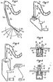
- the reference 11 designates a string of the harp and the reference 12 the base plate of the saddle on which are mounted the hydraulic micro-jacks and the devices for immobilizing the rope that they control.
- the device for immobilizing the rope is a fork with two branches 13 similar to the conventional fork which is rotated to create a twist on the rope.
- the fork is simultaneously rotated and moved in the direction of the rope so that in the inactive position shown in Figure 4 the teeth 13 of the fork are further from the rope which reduces the risk of "zinc coating" ".
- This movement is obtained from the single-action hydraulic cylinder 14 with return to the rest position by a spring 15, by providing the rod 16 of the cylinder which carries the base plate 17 of the fork, with a helical groove 18 in which engages a helical tooth 19 carried by the cover plate 20 of the jack.
- the fork moves by turning to twist the rope 11 with a force which is a function of the slope of the ramp 18, the section of the jack and the hydraulic pressure Implementation.
- the rope 11 is no longer twisted but pinched.
- two jaws 21 are articulated at 22 on a base piece 23 fixed on the plate 12 so that the two clamping notches 21 'of the cord 11' of the jaws are on either side of the rope 11, the articulation point 22 of each jaw being located beyond the longitudinal plane containing the rope so that the jaws overlap by being superimposed along the axial plane.
- the two jaws each have a slot 24 in their longitudinal direction, these slots overlapping in the axial plane.
- a stud 25 which is carried by a head 26 integral with the rod 27 of the piston of the micro-jack 28 which is a single-acting jack with return spring 29.
- FIG. 8 and 9 uses the blocking of the rope 11 in the altered position by a bezel 30, with which cooperates a pusher 31.
- the bezel 30 is, for blocking the rope (Figure 9 ) moved to the plate 12 to come to be applied by its transverse branch on the rope while the pusher 31 is moved in the opposite direction to strongly pinch the rope against said transverse branch.
- the bezel 30 is also locked in the end position by fitting a conical cavity 32 surrounding its control rod on a frustoconical projection 33 secured to the plate 12.
- the displacements in opposite directions of the bezel 30 and the pusher 31 are produced by a double-acting hydraulic cylinder 34.
- This cylinder comprises a main piston 35, the rod 36 of which is integral with the bezel 30.
- the rod 36 is axially bored to form the cylinder of a second piston 37, the rod of which forms the pusher 31.
- the cylinder chamber above the piston 35 is in communication with the chamber below the piston 37 through one or more orifices 38 passing through the hollow piston rod 36 in the vicinity of the piston 35.
- the cylinder chamber 34 located above the piston 35 is supplied by a connector 39 and the pistons are returned to one another, to separate the transverse branch of the telescope 30 from the pusher 31 and release the rope by springs 40 and 41.
Landscapes
- Physics & Mathematics (AREA)
- Engineering & Computer Science (AREA)
- Acoustics & Sound (AREA)
- Multimedia (AREA)
- Earth Drilling (AREA)
- Stringed Musical Instruments (AREA)
Applications Claiming Priority (2)
| Application Number | Priority Date | Filing Date | Title |
|---|---|---|---|
| FR8213840A FR2531559A1 (fr) | 1982-08-09 | 1982-08-09 | Perfectionnement aux harpes de concert |
| FR8213840 | 1982-08-09 |
Publications (1)
| Publication Number | Publication Date |
|---|---|
| EP0104098A1 true EP0104098A1 (de) | 1984-03-28 |
Family
ID=9276734
Family Applications (1)
| Application Number | Title | Priority Date | Filing Date |
|---|---|---|---|
| EP83401575A Withdrawn EP0104098A1 (de) | 1982-08-09 | 1983-07-29 | Konzertharfen |
Country Status (3)
| Country | Link |
|---|---|
| US (1) | US4599931A (de) |
| EP (1) | EP0104098A1 (de) |
| FR (1) | FR2531559A1 (de) |
Cited By (1)
| Publication number | Priority date | Publication date | Assignee | Title |
|---|---|---|---|---|
| WO1988002910A1 (en) * | 1986-10-13 | 1988-04-21 | Pluck Limited | A device for selecting chord positions for a stringed instrument |
Families Citing this family (2)
| Publication number | Priority date | Publication date | Assignee | Title |
|---|---|---|---|---|
| US5468819A (en) * | 1993-11-16 | 1995-11-21 | The B.F. Goodrich Company | Process for making polymers containing a norbornene repeating unit by addition polymerization using an organo (nickel or palladium) complex |
| CN104036757A (zh) * | 2014-06-20 | 2014-09-10 | 慈溪市绿派新能源科技有限公司 | 装配式二胡多功能千斤 |
Citations (3)
| Publication number | Priority date | Publication date | Assignee | Title |
|---|---|---|---|---|
| US2812681A (en) * | 1953-11-13 | 1957-11-12 | Arthur L Carron | Electrically operated key-changing harp mechanism |
| US3494238A (en) * | 1968-02-08 | 1970-02-10 | Darell A Crites | Stringed instrument with pre-programmed instantaneous selection of multiple chromatic changes |
| FR2229108A1 (de) * | 1973-05-11 | 1974-12-06 | Petutschnigg Karl |
Family Cites Families (1)
| Publication number | Priority date | Publication date | Assignee | Title |
|---|---|---|---|---|
| US3739680A (en) * | 1971-08-24 | 1973-06-19 | Lyon & Healy Inc | Harp construction |
-
1982
- 1982-08-09 FR FR8213840A patent/FR2531559A1/fr active Granted
-
1983
- 1983-07-29 EP EP83401575A patent/EP0104098A1/de not_active Withdrawn
- 1983-08-09 US US06/521,554 patent/US4599931A/en not_active Expired - Fee Related
Patent Citations (3)
| Publication number | Priority date | Publication date | Assignee | Title |
|---|---|---|---|---|
| US2812681A (en) * | 1953-11-13 | 1957-11-12 | Arthur L Carron | Electrically operated key-changing harp mechanism |
| US3494238A (en) * | 1968-02-08 | 1970-02-10 | Darell A Crites | Stringed instrument with pre-programmed instantaneous selection of multiple chromatic changes |
| FR2229108A1 (de) * | 1973-05-11 | 1974-12-06 | Petutschnigg Karl |
Cited By (1)
| Publication number | Priority date | Publication date | Assignee | Title |
|---|---|---|---|---|
| WO1988002910A1 (en) * | 1986-10-13 | 1988-04-21 | Pluck Limited | A device for selecting chord positions for a stringed instrument |
Also Published As
| Publication number | Publication date |
|---|---|
| FR2531559B1 (de) | 1985-03-29 |
| FR2531559A1 (fr) | 1984-02-10 |
| US4599931A (en) | 1986-07-15 |
Similar Documents
| Publication | Publication Date | Title |
|---|---|---|
| FR2541226A1 (fr) | Derailleur pour une bicyclette | |
| EP0186602B1 (de) | Vorrichtung für Steuerung, Vorwahl und Anzeige der Hintergangschaltung von Fahrrädern und dergleichen | |
| FR2541225A1 (fr) | Derailleur pour une bicyclette | |
| FR2581957A1 (fr) | Derailleur arriere pour une bicyclette | |
| FR2574144A1 (fr) | Derailleur arriere pour une bicyclette | |
| EP0104098A1 (de) | Konzertharfen | |
| EP0385818A1 (de) | Falz- und Schneidapparat für eine Druckpapierbahn | |
| FR2564165A1 (fr) | Dispositif pour actionner une boite a vitesses dont la synchronisation est pilotee par un calculateur electronique | |
| EP1130610B1 (de) | Vorrichtung für den Betätigungsmechanismus eines elektrischen Gerätes und Betätigungsmechanismus mit einer solchen Vorrichtung | |
| FR2610167A1 (fr) | Secateur-elagueur | |
| EP0085266B1 (de) | Harfe mit Umstimmvorrichtung | |
| EP1072735B1 (de) | Verlegehilfevorrichtung zum Anbringen von Täfelung | |
| EP0370914A1 (de) | Spannkopf mit Spielausgleich | |
| EP0918580A1 (de) | Vorrichtung zum verschieben eines teils einer maschine und ausüben einer kraft am bewegungsende | |
| FR2492856A1 (fr) | Machine a coudre comportant une griffe d'entrainement mobile transversalement | |
| EP0152363B1 (de) | Maschinen zum Schneiden von Silageblöcken | |
| CH720110A2 (fr) | Organe de commande bistable de pièce d'horlogerie et pièce d'horlogerie comportant un tel organe. | |
| WO2024057066A1 (fr) | Dispositif d'assistance à la manœuvre d'un outil-pince et outil-pince le comportant | |
| CH720109A2 (fr) | Mécanisme de sonnerie doté de plusieurs modes de fonctionnement. | |
| FR2569521A1 (fr) | Secateur a main perfectionne | |
| FR2633996A1 (fr) | Reducteur de rotation entre un arbre menant et un arbre mene | |
| EP4660716A1 (de) | Uhrmechanismus mit einer vorrichtung zur korrektur von zwei anzeigevorrichtungen | |
| EP0095430A1 (de) | Stangentransfervorrichtung | |
| CA2166894A1 (fr) | Ski equipe d'un dispositif pour ski de fond | |
| FR2515865A1 (fr) | Commutateur a plusieurs fonctions |
Legal Events
| Date | Code | Title | Description |
|---|---|---|---|
| PUAI | Public reference made under article 153(3) epc to a published international application that has entered the european phase |
Free format text: ORIGINAL CODE: 0009012 |
|
| AK | Designated contracting states |
Designated state(s): DE FR GB IT |
|
| 17P | Request for examination filed |
Effective date: 19840924 |
|
| STAA | Information on the status of an ep patent application or granted ep patent |
Free format text: STATUS: THE APPLICATION HAS BEEN WITHDRAWN |
|
| 18W | Application withdrawn |
Withdrawal date: 19860906 |
|
| RIN1 | Information on inventor provided before grant (corrected) |
Inventor name: GARNIER, JOEL |