EP0103495A2 - Barre pour condensateur et son procédé de fabrication - Google Patents
Barre pour condensateur et son procédé de fabrication Download PDFInfo
- Publication number
- EP0103495A2 EP0103495A2 EP83401006A EP83401006A EP0103495A2 EP 0103495 A2 EP0103495 A2 EP 0103495A2 EP 83401006 A EP83401006 A EP 83401006A EP 83401006 A EP83401006 A EP 83401006A EP 0103495 A2 EP0103495 A2 EP 0103495A2
- Authority
- EP
- European Patent Office
- Prior art keywords
- capacitor
- fold
- strip
- terminal
- edge
- Prior art date
- Legal status (The legal status is an assumption and is not a legal conclusion. Google has not performed a legal analysis and makes no representation as to the accuracy of the status listed.)
- Granted
Links
Images
Classifications
-
- H—ELECTRICITY
- H01—ELECTRIC ELEMENTS
- H01G—CAPACITORS; CAPACITORS, RECTIFIERS, DETECTORS, SWITCHING DEVICES, LIGHT-SENSITIVE OR TEMPERATURE-SENSITIVE DEVICES OF THE ELECTROLYTIC TYPE
- H01G4/00—Fixed capacitors; Processes of their manufacture
- H01G4/002—Details
- H01G4/228—Terminals
- H01G4/242—Terminals the capacitive element surrounding the terminal
- H01G4/245—Tabs between the layers of a rolled electrode
Definitions
- This invention relates to capacitors and more particularly to the terminal which extends from one end of the capacitor.
- capacitors are manufactured from a metal foil and a dielectric material wound in a circular or rectangular shape to form a capacitor of a given capacitance.
- a capacitor may be found in U.S. Patent 1,900,352 issued July 13, 1929 and entitled "Condenser and Method of Making Same".
- the conducting foil used in such capacitors is usually extremely thin and fragile and a metal strip of electrically conductive material is generally attached to each end of the foil as terminals which may then be connected into an electrical circuit.
- This invention provides a terminal, one end of which will not tear away from the foil to which it is attached when the other end is moved a small distance. It also allows a conductor to be soldered to the terminal without allowing the solder to flow into the folds which would prevent the folds from allowing movement of a portion of the terminal.
- Another advantage of the invention is that it allows visual inspection of the solder joints between the tabs of several capacitors and a conductor that connects the tabs together.
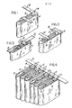
- FIGURES 1, 2 and 3 illustrate how the capacitor tab is folded.
- FIGURE 4 illustrates the capacitor tabs soldered to a conductors.
- FIGURE 1 illustrates a capacitor 1 of the type comprised of a plurality of layers of foil and insulation wound to form a capacitor having terminals 2 that project beyond a lateral edge of the foil and insulation.
- the terminal 2 has a fold A, which is a 90 degree bend so that the terminal 2 extends in a direction past one edge 3 of the capacitor 1.
- FIGURE 2 illustrates a second fold B, which is a 180 degree bend, so that the terminal 2 extends in a direction past another edge 4 of said capacitor 1.
- FIGURE 3 illustrates a third fold C which is at an oblique angle (preferably 45 degrees) to a lateral edge of the terminal 2.
- FIGURES 1, 2 and 3 illustrate a method of forming a terminal 2 from one end of an electrically conductive strip connected to the foil of a capacitor 1.
- the method includes making a first fold A (90 degrees) in the terminal 2 in a direction of one of the edges 3 of the capacitor; making a second fold B (180 degrees) in the terminal 2 in a direction of another portion of the edges 4 of the capacitor; and making a third fold C (45 degrees) in the terminal at an oblique angle to the lateral edges of the strip so that one end of the terminal 2 is laterally spaced from said folds.
- FIGURE 4 illustrates how an electrical conductor 5 is attached to one end of each of the terminals 2 along one side of the capacitors 1.
- Another metal conductor may be attached to the ends of the other terminals 2. Because of the oblique fold C in the terminals 2 the end of each terminal 2 may be soldered to the conductor 5 at a position that is not above the folds A or B. This prevents solder from flowing down onto the folds which would prevent the folds A or B from expanding when the conductor 5 is moved a small distance.
- the folds A and B in each terminal permit some movement of the end of the terminal 2 before placing a. strain on the connection between the other end of the terminal 2 and the thin foil of the capacitor 1.
Landscapes
- Engineering & Computer Science (AREA)
- Power Engineering (AREA)
- Manufacturing & Machinery (AREA)
- Microelectronics & Electronic Packaging (AREA)
- Fixed Capacitors And Capacitor Manufacturing Machines (AREA)
Applications Claiming Priority (2)
| Application Number | Priority Date | Filing Date | Title |
|---|---|---|---|
| US390165 | 1982-06-21 | ||
| US06/390,165 US4413305A (en) | 1982-06-21 | 1982-06-21 | Terminal for a capacitor and a method of forming same |
Publications (3)
| Publication Number | Publication Date |
|---|---|
| EP0103495A2 true EP0103495A2 (fr) | 1984-03-21 |
| EP0103495A3 EP0103495A3 (en) | 1985-04-17 |
| EP0103495B1 EP0103495B1 (fr) | 1989-01-11 |
Family
ID=23541360
Family Applications (1)
| Application Number | Title | Priority Date | Filing Date |
|---|---|---|---|
| EP83401006A Expired EP0103495B1 (fr) | 1982-06-21 | 1983-05-20 | Barre pour condensateur et son procédé de fabrication |
Country Status (5)
| Country | Link |
|---|---|
| US (1) | US4413305A (fr) |
| EP (1) | EP0103495B1 (fr) |
| JP (1) | JPS594112A (fr) |
| CA (1) | CA1181825A (fr) |
| DE (1) | DE3378942D1 (fr) |
Cited By (2)
| Publication number | Priority date | Publication date | Assignee | Title |
|---|---|---|---|---|
| US5104796A (en) * | 1987-04-06 | 1992-04-14 | International Minerals & Chemical Corp. | High titer production of human somatomedin c |
| DE4238643A1 (de) * | 1992-11-16 | 1994-05-19 | Siemens Matsushita Components | Elektrischer Kondensator mit kleiner Eigeninduktivität für die Energie-Elektronik |
Families Citing this family (5)
| Publication number | Priority date | Publication date | Assignee | Title |
|---|---|---|---|---|
| GB8420347D0 (en) * | 1984-08-10 | 1984-09-12 | Molins Plc | Conveying rod-like articles |
| GB2213322A (en) * | 1987-08-21 | 1989-08-09 | Secr Defence | Terminating a flat wound capacitor used in a discharge circuit |
| JPH03124010A (ja) * | 1989-10-08 | 1991-05-27 | Murata Mfg Co Ltd | 電子部品の端子 |
| GB2293492A (en) * | 1994-09-07 | 1996-03-27 | Cenwick Electronics Ltd | Terminating electronic components |
| US6327133B1 (en) * | 1999-07-02 | 2001-12-04 | American Shizuki Corporation | Nylon shell doghouse capacitor assembly |
Family Cites Families (13)
| Publication number | Priority date | Publication date | Assignee | Title |
|---|---|---|---|---|
| US1248829A (en) * | 1915-09-17 | 1917-12-04 | Wagner Electric Mfg Co | Condenser-terminal and method of forming same. |
| US1833392A (en) * | 1925-12-29 | 1931-11-24 | Dubilier Condenser Corp | Electrical condenser |
| US1796683A (en) * | 1926-12-16 | 1931-03-17 | Western Electric Co | Method of producing articles |
| US1862297A (en) * | 1929-03-15 | 1932-06-07 | Gen Electric | Capacitor and method forming the same |
| US1900352A (en) * | 1929-07-13 | 1933-03-07 | Grigsby Grunow Co | Condenser and method of making the same |
| DE555420C (de) * | 1929-08-16 | 1933-10-27 | Gerhard Jaeger | Vorrichtung zur Verbindung elektrischer Batterien, insbesondere von Taschenlampenbatterien |
| US2049585A (en) * | 1932-05-23 | 1936-08-04 | Economy Fuse And Mfg Co | Electrical device |
| US2004616A (en) * | 1933-03-09 | 1935-06-11 | Western Electric Co | Electric apparatus |
| DE868480C (de) * | 1943-02-26 | 1953-02-26 | Bosch Gmbh Robert | Elektrische Kondensatoren fuer Hochstrombelastung |
| GB713058A (en) * | 1951-09-01 | 1954-08-04 | Siemens Ag | Improvements in or relating to electric condensers |
| US2908886A (en) * | 1955-10-28 | 1959-10-13 | Cornell Dubilier Electric | Terminal lug for a capacitor or the like |
| US3060356A (en) * | 1956-05-14 | 1962-10-23 | Cornell Dubilier Electric | Tubular capacitor and method of making same |
| US3267343A (en) * | 1965-03-01 | 1966-08-16 | Illinois Tool Works | Wound capacitor and lead assembly |
-
1982
- 1982-06-21 US US06/390,165 patent/US4413305A/en not_active Expired - Lifetime
-
1983
- 1983-02-03 CA CA000420814A patent/CA1181825A/fr not_active Expired
- 1983-05-20 DE DE8383401006T patent/DE3378942D1/de not_active Expired
- 1983-05-20 EP EP83401006A patent/EP0103495B1/fr not_active Expired
- 1983-06-21 JP JP58110308A patent/JPS594112A/ja active Granted
Cited By (2)
| Publication number | Priority date | Publication date | Assignee | Title |
|---|---|---|---|---|
| US5104796A (en) * | 1987-04-06 | 1992-04-14 | International Minerals & Chemical Corp. | High titer production of human somatomedin c |
| DE4238643A1 (de) * | 1992-11-16 | 1994-05-19 | Siemens Matsushita Components | Elektrischer Kondensator mit kleiner Eigeninduktivität für die Energie-Elektronik |
Also Published As
| Publication number | Publication date |
|---|---|
| JPS594112A (ja) | 1984-01-10 |
| DE3378942D1 (en) | 1989-02-16 |
| US4413305A (en) | 1983-11-01 |
| EP0103495A3 (en) | 1985-04-17 |
| JPH0371763B2 (fr) | 1991-11-14 |
| EP0103495B1 (fr) | 1989-01-11 |
| CA1181825A (fr) | 1985-01-29 |
Similar Documents
| Publication | Publication Date | Title |
|---|---|---|
| JP2561883B2 (ja) | フィルターコネクタ用の接地プレートおよびその製造法 | |
| US4591814A (en) | Electronic component comprising printed circuit elements disposed on a folded tape and method of making such component | |
| US4413305A (en) | Terminal for a capacitor and a method of forming same | |
| US4308513A (en) | Etched magnetic coil | |
| US5041006A (en) | Insulation displacement contact element | |
| GB2034102A (en) | Flat cable | |
| US4113338A (en) | Insulation-piercing contact | |
| US4223786A (en) | Series of electronic components | |
| US2803788A (en) | Electronic module | |
| EP0186765A2 (fr) | Barre terminale pour condensateur "pastille" | |
| US3854075A (en) | Miniature metalized film capacitor | |
| US4307434A (en) | Multi-section capacitor having continuous foil strip interconnections between sections and method of making the same | |
| US2949570A (en) | Low value wound capacitor | |
| US5040094A (en) | 3-terminal capacitor | |
| US4128857A (en) | Pleated metallized film capacitor wound about its center | |
| JP2000091135A (ja) | インダクタンス部品とその製造方法 | |
| JPH0644113U (ja) | インピーダンス素子 | |
| JPH0532993Y2 (fr) | ||
| ATE127281T1 (de) | Isolationsdurchdringender kontakt. | |
| KR950001584Y1 (ko) | 필름콘덴서용 절연지 | |
| JPS6028124Y2 (ja) | 低インピ−ダンス並列電解コンデンサ組立体 | |
| GB2154077A (en) | Connecting a flexible circuit to a rigid circuit board | |
| JPH0547458Y2 (fr) | ||
| US3259686A (en) | Terminal construction and method of manufacture thereof | |
| JPH0737721A (ja) | 積層型コイル |
Legal Events
| Date | Code | Title | Description |
|---|---|---|---|
| PUAI | Public reference made under article 153(3) epc to a published international application that has entered the european phase |
Free format text: ORIGINAL CODE: 0009012 |
|
| 17P | Request for examination filed |
Effective date: 19830609 |
|
| AK | Designated contracting states |
Designated state(s): DE FR GB IT |
|
| PUAL | Search report despatched |
Free format text: ORIGINAL CODE: 0009013 |
|
| AK | Designated contracting states |
Designated state(s): DE FR GB IT |
|
| 17Q | First examination report despatched |
Effective date: 19870309 |
|
| RAP1 | Party data changed (applicant data changed or rights of an application transferred) |
Owner name: ALLIED-SIGNAL INC. |
|
| GRAA | (expected) grant |
Free format text: ORIGINAL CODE: 0009210 |
|
| ITF | It: translation for a ep patent filed | ||
| AK | Designated contracting states |
Kind code of ref document: B1 Designated state(s): DE FR GB IT |
|
| REF | Corresponds to: |
Ref document number: 3378942 Country of ref document: DE Date of ref document: 19890216 |
|
| ET | Fr: translation filed | ||
| PLBE | No opposition filed within time limit |
Free format text: ORIGINAL CODE: 0009261 |
|
| STAA | Information on the status of an ep patent application or granted ep patent |
Free format text: STATUS: NO OPPOSITION FILED WITHIN TIME LIMIT |
|
| 26N | No opposition filed | ||
| ITTA | It: last paid annual fee | ||
| PGFP | Annual fee paid to national office [announced via postgrant information from national office to epo] |
Ref country code: GB Payment date: 19900619 Year of fee payment: 8 |
|
| PGFP | Annual fee paid to national office [announced via postgrant information from national office to epo] |
Ref country code: FR Payment date: 19900622 Year of fee payment: 8 |
|
| PGFP | Annual fee paid to national office [announced via postgrant information from national office to epo] |
Ref country code: DE Payment date: 19900731 Year of fee payment: 8 |
|
| PG25 | Lapsed in a contracting state [announced via postgrant information from national office to epo] |
Ref country code: GB Effective date: 19910520 |
|
| GBPC | Gb: european patent ceased through non-payment of renewal fee | ||
| PG25 | Lapsed in a contracting state [announced via postgrant information from national office to epo] |
Ref country code: FR Effective date: 19920131 |
|
| PG25 | Lapsed in a contracting state [announced via postgrant information from national office to epo] |
Ref country code: DE Effective date: 19920303 |
|
| REG | Reference to a national code |
Ref country code: FR Ref legal event code: ST |