EP0103495A2 - A terminal for a capacitor and method of forming same - Google Patents
A terminal for a capacitor and method of forming same Download PDFInfo
- Publication number
- EP0103495A2 EP0103495A2 EP83401006A EP83401006A EP0103495A2 EP 0103495 A2 EP0103495 A2 EP 0103495A2 EP 83401006 A EP83401006 A EP 83401006A EP 83401006 A EP83401006 A EP 83401006A EP 0103495 A2 EP0103495 A2 EP 0103495A2
- Authority
- EP
- European Patent Office
- Prior art keywords
- capacitor
- fold
- strip
- terminal
- edge
- Prior art date
- Legal status (The legal status is an assumption and is not a legal conclusion. Google has not performed a legal analysis and makes no representation as to the accuracy of the status listed.)
- Granted
Links
Images
Classifications
-
- H—ELECTRICITY
- H01—ELECTRIC ELEMENTS
- H01G—CAPACITORS; CAPACITORS, RECTIFIERS, DETECTORS, SWITCHING DEVICES, LIGHT-SENSITIVE OR TEMPERATURE-SENSITIVE DEVICES OF THE ELECTROLYTIC TYPE
- H01G4/00—Fixed capacitors; Processes of their manufacture
- H01G4/002—Details
- H01G4/228—Terminals
- H01G4/242—Terminals the capacitive element surrounding the terminal
- H01G4/245—Tabs between the layers of a rolled electrode
Definitions
- This invention relates to capacitors and more particularly to the terminal which extends from one end of the capacitor.
- capacitors are manufactured from a metal foil and a dielectric material wound in a circular or rectangular shape to form a capacitor of a given capacitance.
- a capacitor may be found in U.S. Patent 1,900,352 issued July 13, 1929 and entitled "Condenser and Method of Making Same".
- the conducting foil used in such capacitors is usually extremely thin and fragile and a metal strip of electrically conductive material is generally attached to each end of the foil as terminals which may then be connected into an electrical circuit.
- This invention provides a terminal, one end of which will not tear away from the foil to which it is attached when the other end is moved a small distance. It also allows a conductor to be soldered to the terminal without allowing the solder to flow into the folds which would prevent the folds from allowing movement of a portion of the terminal.
- Another advantage of the invention is that it allows visual inspection of the solder joints between the tabs of several capacitors and a conductor that connects the tabs together.
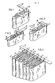
- FIGURES 1, 2 and 3 illustrate how the capacitor tab is folded.
- FIGURE 4 illustrates the capacitor tabs soldered to a conductors.
- FIGURE 1 illustrates a capacitor 1 of the type comprised of a plurality of layers of foil and insulation wound to form a capacitor having terminals 2 that project beyond a lateral edge of the foil and insulation.
- the terminal 2 has a fold A, which is a 90 degree bend so that the terminal 2 extends in a direction past one edge 3 of the capacitor 1.
- FIGURE 2 illustrates a second fold B, which is a 180 degree bend, so that the terminal 2 extends in a direction past another edge 4 of said capacitor 1.
- FIGURE 3 illustrates a third fold C which is at an oblique angle (preferably 45 degrees) to a lateral edge of the terminal 2.
- FIGURES 1, 2 and 3 illustrate a method of forming a terminal 2 from one end of an electrically conductive strip connected to the foil of a capacitor 1.
- the method includes making a first fold A (90 degrees) in the terminal 2 in a direction of one of the edges 3 of the capacitor; making a second fold B (180 degrees) in the terminal 2 in a direction of another portion of the edges 4 of the capacitor; and making a third fold C (45 degrees) in the terminal at an oblique angle to the lateral edges of the strip so that one end of the terminal 2 is laterally spaced from said folds.
- FIGURE 4 illustrates how an electrical conductor 5 is attached to one end of each of the terminals 2 along one side of the capacitors 1.
- Another metal conductor may be attached to the ends of the other terminals 2. Because of the oblique fold C in the terminals 2 the end of each terminal 2 may be soldered to the conductor 5 at a position that is not above the folds A or B. This prevents solder from flowing down onto the folds which would prevent the folds A or B from expanding when the conductor 5 is moved a small distance.
- the folds A and B in each terminal permit some movement of the end of the terminal 2 before placing a. strain on the connection between the other end of the terminal 2 and the thin foil of the capacitor 1.
Landscapes
- Engineering & Computer Science (AREA)
- Power Engineering (AREA)
- Manufacturing & Machinery (AREA)
- Microelectronics & Electronic Packaging (AREA)
- Fixed Capacitors And Capacitor Manufacturing Machines (AREA)
Abstract
Description
- This invention relates to capacitors and more particularly to the terminal which extends from one end of the capacitor.
- Some capacitors are manufactured from a metal foil and a dielectric material wound in a circular or rectangular shape to form a capacitor of a given capacitance. Such a capacitor may be found in U.S. Patent 1,900,352 issued July 13, 1929 and entitled "Condenser and Method of Making Same". The conducting foil used in such capacitors is usually extremely thin and fragile and a metal strip of electrically conductive material is generally attached to each end of the foil as terminals which may then be connected into an electrical circuit.
- When an electrical conductor is connected to the terminal members it is customary to solder such terminals to the conductor. If the conductor moves it also moves one end of the terminal which may move the other end of the terminal and cause the terminal to tear away from the foil to which it was attached. One example of a capacitor terminal may be found in U.S. Patent 1,248,829 issued December 4, 1917 and entitled "Condenser Terminal and Method of Forming Same".
- This invention provides a terminal, one end of which will not tear away from the foil to which it is attached when the other end is moved a small distance. It also allows a conductor to be soldered to the terminal without allowing the solder to flow into the folds which would prevent the folds from allowing movement of a portion of the terminal.
- Accordingly, it is an advantage of this invention to provide a terminal, one end of which may be moved a small distance in a direction parallel or perpendicular to the central axis of a capacitor without causing strain on or movement of the other end of the terminal.
- Another advantage of the invention is that it allows visual inspection of the solder joints between the tabs of several capacitors and a conductor that connects the tabs together.
- FIGURES 1, 2 and 3 illustrate how the capacitor tab is folded.
- FIGURE 4 illustrates the capacitor tabs soldered to a conductors.
- Referring now to the drawings, FIGURE 1 illustrates a capacitor 1 of the type comprised of a plurality of layers of foil and insulation wound to form a
capacitor having terminals 2 that project beyond a lateral edge of the foil and insulation. Theterminal 2 has a fold A, which is a 90 degree bend so that theterminal 2 extends in a direction past oneedge 3 of the capacitor 1. - FIGURE 2 illustrates a second fold B, which is a 180 degree bend, so that the
terminal 2 extends in a direction past anotheredge 4 of said capacitor 1. - FIGURE 3 illustrates a third fold C which is at an oblique angle (preferably 45 degrees) to a lateral edge of the
terminal 2. - FIGURES 1, 2 and 3 illustrate a method of forming a
terminal 2 from one end of an electrically conductive strip connected to the foil of a capacitor 1. The method includes making a first fold A (90 degrees) in theterminal 2 in a direction of one of theedges 3 of the capacitor; making a second fold B (180 degrees) in theterminal 2 in a direction of another portion of theedges 4 of the capacitor; and making a third fold C (45 degrees) in the terminal at an oblique angle to the lateral edges of the strip so that one end of theterminal 2 is laterally spaced from said folds. - FIGURE 4 illustrates how an electrical conductor 5 is attached to one end of each of the
terminals 2 along one side of the capacitors 1. Another metal conductor may be attached to the ends of theother terminals 2. Because of the oblique fold C in theterminals 2 the end of eachterminal 2 may be soldered to the conductor 5 at a position that is not above the folds A or B. This prevents solder from flowing down onto the folds which would prevent the folds A or B from expanding when the conductor 5 is moved a small distance. The folds A and B in each terminal permit some movement of the end of theterminal 2 before placing a. strain on the connection between the other end of theterminal 2 and the thin foil of the capacitor 1. - While a preferred embodiment of this invention has been disclosed, it will be apparent to those skilled in the art, that changes may be made to the invention as set forth in the appended claims, and in some instances, certain features of the invention may be used to advantage without corresponding use of other features. For instance there may be more than two folds in the
terminal 2 to provide strain relief so long as there is also a fold at an oblique angle to the lateral edge of the strip forming the terminal. Accordingly, it is intended that the illustrative and descriptive materials herein be used to illustrate the principles of the invention and not to limit the scope thereof.
Claims (7)
Applications Claiming Priority (2)
| Application Number | Priority Date | Filing Date | Title |
|---|---|---|---|
| US390165 | 1982-06-21 | ||
| US06/390,165 US4413305A (en) | 1982-06-21 | 1982-06-21 | Terminal for a capacitor and a method of forming same |
Publications (3)
| Publication Number | Publication Date |
|---|---|
| EP0103495A2 true EP0103495A2 (en) | 1984-03-21 |
| EP0103495A3 EP0103495A3 (en) | 1985-04-17 |
| EP0103495B1 EP0103495B1 (en) | 1989-01-11 |
Family
ID=23541360
Family Applications (1)
| Application Number | Title | Priority Date | Filing Date |
|---|---|---|---|
| EP83401006A Expired EP0103495B1 (en) | 1982-06-21 | 1983-05-20 | A terminal for a capacitor and method of forming same |
Country Status (5)
| Country | Link |
|---|---|
| US (1) | US4413305A (en) |
| EP (1) | EP0103495B1 (en) |
| JP (1) | JPS594112A (en) |
| CA (1) | CA1181825A (en) |
| DE (1) | DE3378942D1 (en) |
Cited By (2)
| Publication number | Priority date | Publication date | Assignee | Title |
|---|---|---|---|---|
| US5104796A (en) * | 1987-04-06 | 1992-04-14 | International Minerals & Chemical Corp. | High titer production of human somatomedin c |
| DE4238643A1 (en) * | 1992-11-16 | 1994-05-19 | Siemens Matsushita Components | Electrical capacitor with low self-inductance for energy electronics |
Families Citing this family (5)
| Publication number | Priority date | Publication date | Assignee | Title |
|---|---|---|---|---|
| GB8420347D0 (en) * | 1984-08-10 | 1984-09-12 | Molins Plc | Conveying rod-like articles |
| GB2213322A (en) * | 1987-08-21 | 1989-08-09 | Secr Defence | Terminating a flat wound capacitor used in a discharge circuit |
| JPH03124010A (en) * | 1989-10-08 | 1991-05-27 | Murata Mfg Co Ltd | Terminal of electronic component |
| GB2293492A (en) * | 1994-09-07 | 1996-03-27 | Cenwick Electronics Ltd | Terminating electronic components |
| US6327133B1 (en) * | 1999-07-02 | 2001-12-04 | American Shizuki Corporation | Nylon shell doghouse capacitor assembly |
Family Cites Families (13)
| Publication number | Priority date | Publication date | Assignee | Title |
|---|---|---|---|---|
| US1248829A (en) * | 1915-09-17 | 1917-12-04 | Wagner Electric Mfg Co | Condenser-terminal and method of forming same. |
| US1833392A (en) * | 1925-12-29 | 1931-11-24 | Dubilier Condenser Corp | Electrical condenser |
| US1796683A (en) * | 1926-12-16 | 1931-03-17 | Western Electric Co | Method of producing articles |
| US1862297A (en) * | 1929-03-15 | 1932-06-07 | Gen Electric | Capacitor and method forming the same |
| US1900352A (en) * | 1929-07-13 | 1933-03-07 | Grigsby Grunow Co | Condenser and method of making the same |
| DE555420C (en) * | 1929-08-16 | 1933-10-27 | Gerhard Jaeger | Device for connecting electric batteries, in particular flashlight batteries |
| US2049585A (en) * | 1932-05-23 | 1936-08-04 | Economy Fuse And Mfg Co | Electrical device |
| US2004616A (en) * | 1933-03-09 | 1935-06-11 | Western Electric Co | Electric apparatus |
| DE868480C (en) * | 1943-02-26 | 1953-02-26 | Bosch Gmbh Robert | Electrical capacitors for high current loads |
| GB713058A (en) * | 1951-09-01 | 1954-08-04 | Siemens Ag | Improvements in or relating to electric condensers |
| US2908886A (en) * | 1955-10-28 | 1959-10-13 | Cornell Dubilier Electric | Terminal lug for a capacitor or the like |
| US3060356A (en) * | 1956-05-14 | 1962-10-23 | Cornell Dubilier Electric | Tubular capacitor and method of making same |
| US3267343A (en) * | 1965-03-01 | 1966-08-16 | Illinois Tool Works | Wound capacitor and lead assembly |
-
1982
- 1982-06-21 US US06/390,165 patent/US4413305A/en not_active Expired - Lifetime
-
1983
- 1983-02-03 CA CA000420814A patent/CA1181825A/en not_active Expired
- 1983-05-20 DE DE8383401006T patent/DE3378942D1/en not_active Expired
- 1983-05-20 EP EP83401006A patent/EP0103495B1/en not_active Expired
- 1983-06-21 JP JP58110308A patent/JPS594112A/en active Granted
Cited By (2)
| Publication number | Priority date | Publication date | Assignee | Title |
|---|---|---|---|---|
| US5104796A (en) * | 1987-04-06 | 1992-04-14 | International Minerals & Chemical Corp. | High titer production of human somatomedin c |
| DE4238643A1 (en) * | 1992-11-16 | 1994-05-19 | Siemens Matsushita Components | Electrical capacitor with low self-inductance for energy electronics |
Also Published As
| Publication number | Publication date |
|---|---|
| JPS594112A (en) | 1984-01-10 |
| DE3378942D1 (en) | 1989-02-16 |
| US4413305A (en) | 1983-11-01 |
| EP0103495A3 (en) | 1985-04-17 |
| JPH0371763B2 (en) | 1991-11-14 |
| EP0103495B1 (en) | 1989-01-11 |
| CA1181825A (en) | 1985-01-29 |
Similar Documents
| Publication | Publication Date | Title |
|---|---|---|
| JP2561883B2 (en) | Ground plate for filter connector and manufacturing method thereof | |
| US4591814A (en) | Electronic component comprising printed circuit elements disposed on a folded tape and method of making such component | |
| US4413305A (en) | Terminal for a capacitor and a method of forming same | |
| US4308513A (en) | Etched magnetic coil | |
| US5041006A (en) | Insulation displacement contact element | |
| GB2034102A (en) | Flat cable | |
| US4113338A (en) | Insulation-piercing contact | |
| US4223786A (en) | Series of electronic components | |
| US2803788A (en) | Electronic module | |
| EP0186765A2 (en) | End termination for chip capacitor | |
| US3854075A (en) | Miniature metalized film capacitor | |
| US4307434A (en) | Multi-section capacitor having continuous foil strip interconnections between sections and method of making the same | |
| US2949570A (en) | Low value wound capacitor | |
| US5040094A (en) | 3-terminal capacitor | |
| US4128857A (en) | Pleated metallized film capacitor wound about its center | |
| JP2000091135A (en) | Inductance component and producing method thereof | |
| JPH0644113U (en) | Impedance element | |
| JPH0532993Y2 (en) | ||
| ATE127281T1 (en) | INSULATION-PENETRATING CONTACT. | |
| KR950001584Y1 (en) | Insulating paper for film condenser | |
| JPS6028124Y2 (en) | Low impedance parallel electrolytic capacitor assembly | |
| GB2154077A (en) | Connecting a flexible circuit to a rigid circuit board | |
| JPH0547458Y2 (en) | ||
| US3259686A (en) | Terminal construction and method of manufacture thereof | |
| JPH0737721A (en) | Laminated coil |
Legal Events
| Date | Code | Title | Description |
|---|---|---|---|
| PUAI | Public reference made under article 153(3) epc to a published international application that has entered the european phase |
Free format text: ORIGINAL CODE: 0009012 |
|
| 17P | Request for examination filed |
Effective date: 19830609 |
|
| AK | Designated contracting states |
Designated state(s): DE FR GB IT |
|
| PUAL | Search report despatched |
Free format text: ORIGINAL CODE: 0009013 |
|
| AK | Designated contracting states |
Designated state(s): DE FR GB IT |
|
| 17Q | First examination report despatched |
Effective date: 19870309 |
|
| RAP1 | Party data changed (applicant data changed or rights of an application transferred) |
Owner name: ALLIED-SIGNAL INC. |
|
| GRAA | (expected) grant |
Free format text: ORIGINAL CODE: 0009210 |
|
| ITF | It: translation for a ep patent filed | ||
| AK | Designated contracting states |
Kind code of ref document: B1 Designated state(s): DE FR GB IT |
|
| REF | Corresponds to: |
Ref document number: 3378942 Country of ref document: DE Date of ref document: 19890216 |
|
| ET | Fr: translation filed | ||
| PLBE | No opposition filed within time limit |
Free format text: ORIGINAL CODE: 0009261 |
|
| STAA | Information on the status of an ep patent application or granted ep patent |
Free format text: STATUS: NO OPPOSITION FILED WITHIN TIME LIMIT |
|
| 26N | No opposition filed | ||
| ITTA | It: last paid annual fee | ||
| PGFP | Annual fee paid to national office [announced via postgrant information from national office to epo] |
Ref country code: GB Payment date: 19900619 Year of fee payment: 8 |
|
| PGFP | Annual fee paid to national office [announced via postgrant information from national office to epo] |
Ref country code: FR Payment date: 19900622 Year of fee payment: 8 |
|
| PGFP | Annual fee paid to national office [announced via postgrant information from national office to epo] |
Ref country code: DE Payment date: 19900731 Year of fee payment: 8 |
|
| PG25 | Lapsed in a contracting state [announced via postgrant information from national office to epo] |
Ref country code: GB Effective date: 19910520 |
|
| GBPC | Gb: european patent ceased through non-payment of renewal fee | ||
| PG25 | Lapsed in a contracting state [announced via postgrant information from national office to epo] |
Ref country code: FR Effective date: 19920131 |
|
| PG25 | Lapsed in a contracting state [announced via postgrant information from national office to epo] |
Ref country code: DE Effective date: 19920303 |
|
| REG | Reference to a national code |
Ref country code: FR Ref legal event code: ST |