EP0103418A2 - Spin dryer with plastic drum - Google Patents
Spin dryer with plastic drum Download PDFInfo
- Publication number
- EP0103418A2 EP0103418A2 EP83304704A EP83304704A EP0103418A2 EP 0103418 A2 EP0103418 A2 EP 0103418A2 EP 83304704 A EP83304704 A EP 83304704A EP 83304704 A EP83304704 A EP 83304704A EP 0103418 A2 EP0103418 A2 EP 0103418A2
- Authority
- EP
- European Patent Office
- Prior art keywords
- drum
- flanges
- motor
- spinning
- parts
- Prior art date
- Legal status (The legal status is an assumption and is not a legal conclusion. Google has not performed a legal analysis and makes no representation as to the accuracy of the status listed.)
- Withdrawn
Links
Images

Classifications
-
- D—TEXTILES; PAPER
- D06—TREATMENT OF TEXTILES OR THE LIKE; LAUNDERING; FLEXIBLE MATERIALS NOT OTHERWISE PROVIDED FOR
- D06F—LAUNDERING, DRYING, IRONING, PRESSING OR FOLDING TEXTILE ARTICLES
- D06F49/00—Domestic spin-dryers or similar spin-dryers not suitable for industrial use
- D06F49/02—Bowl construction
Definitions
- This invention relates to a rotary washing, drying, or tumbling machine of the type which comprises an electric motor driving a spinning drum.
- Such machines are well-known and usually have a steel or aluminium drum. Steel drums and aluminium drums eventually corrode and are in any case expensive and heavy.
- a rotary washing drying or tumbling machine comprises an electric motor adapted to drive a spinning drum, the spinning drum being made of plastics material.
- the spinning drum is made of polypropylene without any glass filling.
- the invention is characterised by a dense metallic or plastic balance ring incorporated in the drum at the end of the drum remote from the motor.
- the drum preferably comprises two substantially cup shaped halves which are joined together in a transverse plane of the drum, and each half has a flange at its larger diameter end, the halves being joined at the two flanges.
- the plastic drum has moulded into it attachment means by which the balance ring may be attached to the drum.
- the attachment means may be in the form of plastic rivet devices.
- a method of forming a rotary washing drying or tumbling machine drum comprising forming two generally cup shaped portions with flanges at their larger ends, bringing the faces of the flanges together and joining them by spin friction welding.
- said flanges each have engaging features.
- one flange may have on its face a circular recess or groove and the other flange may have a corresponding circular protruding ridge adapted to engage the recess or groove to hold the two parts in alignment or registration during the welding process.
- the welding process although called spin friction welding, comprises holding the two parts together in alignment, oscillating the two parts relatively to each other so that the flanges rub at their engaging faces thus producing, by friction, sufficient heat to cause the melting of the immediate surface layers of the flanges, the two drum parts then being pressed together to complete the welding of the two parts once the temperature is sufficient to ensure the melting of the faces.
- the machine may comprise a DC permanent magnet electric motor which is adapted to drive the spinning drum, the spinning drum being located at one end of the motor and a pump located at the other end of the motor so that the motor drives both the drum and pump rotor directly without any intermediate gearing pulleys or the like.
- the spin dryer in Figure 1 is enclosed in a conventional rectangular casing 10 divided into two chambers 11 and 12 by a partition 13, the chamber 11 being sealed from the chamber 12 so as to prevent any water flowing into the chamber 12 which contains among other things the electrical components of the spin dryer.
- the casing 10 has an aperture 14 in its upper face 15 and a hinged door 16 which closes the aperture 14 when the spin dryer is in use.
- the spin dryer is driven by a DC permanent magnet electric motor 17 which has its permanent magnet made of sintered ferritic material so as to provide a small compact powerful DC electric motor.
- the motor 17 is supported by a mounting assembly 18 which has a number of radially extending fingers 19 attached to a portion of casing 13 by resilient mountings 20. Attached to the drive shaft at the upper end of motor 17 is a mount 21 for a plastic drum 22. The drum 22 is screwed as at 23 to the mount 21 and is directly driven by the motor 17. A conventional rubber seal is provided at 24 so as to prevent flow of water through from the upper chamber 11 to the lower chamber 12.
- a pump 25 which is made of plastics material.
- the pump comprises a housing 26 and an integral intake 27 moulded from plastic material and a plastic rotor 28 carried on a shaft 29 supported in sealed bearings 30 and including a rubber seal 31 to prevent any flow of water from the pump into the motor.
- the pump shaft 29 has a key 32 which engages in a slot 33 in the motor shaft 34.
- the pump is directly driven by the DC motor and the spin dryer is also directly driven by the motor shaft at its opposite end.
- No gearing is required and no pulleys or band drives are embodied in the drive to the pump.
- the pump outlet is shown at 35 in Figure 1 and leads to a conventional flexible pipe 36 which may be led away to the normal sink or drain.
- the inlet 27 of the pump is connected by a flexible pipe 37 to drain outlet 38 formed in casing 13.
- the drum 22 comprises two cup shaped mouldings 39 and 40 (Figs. 1 and 3).
- the upper moulding 39 has a round aperture 41 in one end to receive the clothes to be spun dried, and a flange 42 at its lower end. It also has slots 43 for flow of water which is centrifugally expelled from the drum during operation.
- the lower cup shaped portion 40 also has a flange 44 at one end and is closed at the other end and provided with holes through which the screws 23 extend which attach the drum to the drum mount 21.
- Integrally moulded with the upper portion 39 are rivets 45 which extend through holes 46 in a balance ring 47 which is a dense metallic dyecasting attached by the plastic rivets 45 to the drum.
- the dyecasting may for instance be made of material known as Mazak 3 which is a dense metal alloy. Alternatively a very dense plastic ring could be used.
- the main portion of the drum is moulded from polypropylene without the use of glass filling.
- this machine is capable of operating at speeds of the order of 3000 rpm and of reaching full speed in about 7 seconds.
- the two halves of the drum are brought together with the protruding ridge 9b engaging in the circular recess or groove 9b and the two parts are carefully aligned. Both upper and lower parts are then oscillated about their longitudinal axes so that the two flange faces rub in frictional contact and produce heat. This oscillating process is continued until the surfaces of the two flanges are melting or about to melt and then pressure is applied to the two ends of the cup shaped portions 39 and 40 so as to ensure the two parts to weld together at the flange faces.
- the balance ring 47 is then attached to the upper end of the drum by applying a conventional heat upsetting process to the rivets 45 which are moulded integrally with the upper portion of the drum.
Landscapes
- Engineering & Computer Science (AREA)
- Textile Engineering (AREA)
- Detail Structures Of Washing Machines And Dryers (AREA)
- Drying Of Solid Materials (AREA)
Abstract
The invention relates to a rotary washing drying or tumbling machine and particularly to a spin dryer of the type in which an electric motor drives a spinning drum.
The spinning drum (22) is in two cup shaped portions (39) and (40) joined at flanges (44) and (42) by spin friction welding. The upper portion (39) of the drum has apertures (43) through which water can flow to the outside of the drum. Portion (49) has at its upper end a balance ring (47) of dense metal or very dense plastic which is attached to the upper drum portion (39) by plastic rivets.
The lower portion (40) of the drum is attached to a mounting (21) which is then directly attached to a motor shaft.
The two flanges (44) and (42) have cooperating projecting ring and groove features to enable the two drum portions to be brought together and held in precise location during the spin friction welding operation.
The preferred material for the drum is polypropylene.
Description
- This invention relates to a rotary washing, drying, or tumbling machine of the type which comprises an electric motor driving a spinning drum.
- Such machines are well-known and usually have a steel or aluminium drum. Steel drums and aluminium drums eventually corrode and are in any case expensive and heavy.
- In accordance with the present invention a rotary washing drying or tumbling machine comprises an electric motor adapted to drive a spinning drum, the spinning drum being made of plastics material. Preferably the spinning drum is made of polypropylene without any glass filling.
- The invention is characterised by a dense metallic or plastic balance ring incorporated in the drum at the end of the drum remote from the motor.
- The drum preferably comprises two substantially cup shaped halves which are joined together in a transverse plane of the drum, and each half has a flange at its larger diameter end, the halves being joined at the two flanges.
- Again preferably, the plastic drum has moulded into it attachment means by which the balance ring may be attached to the drum. The attachment means may be in the form of plastic rivet devices.
- From another aspect, in accordance with the present invention, there is a method of forming a rotary washing drying or tumbling machine drum comprising forming two generally cup shaped portions with flanges at their larger ends, bringing the faces of the flanges together and joining them by spin friction welding.
- Preferably said flanges each have engaging features. For example one flange may have on its face a circular recess or groove and the other flange may have a corresponding circular protruding ridge adapted to engage the recess or groove to hold the two parts in alignment or registration during the welding process.
- The welding process, although called spin friction welding, comprises holding the two parts together in alignment, oscillating the two parts relatively to each other so that the flanges rub at their engaging faces thus producing, by friction, sufficient heat to cause the melting of the immediate surface layers of the flanges, the two drum parts then being pressed together to complete the welding of the two parts once the temperature is sufficient to ensure the melting of the faces.
- The machine may comprise a DC permanent magnet electric motor which is adapted to drive the spinning drum, the spinning drum being located at one end of the motor and a pump located at the other end of the motor so that the motor drives both the drum and pump rotor directly without any intermediate gearing pulleys or the like.
- In the accompanying drawings:
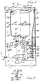
- Figure 1 is an elevation with parts in section of a spin dryer embodying a drum in accordance with the present invention;
- Figure 2 is a scrap section through a portion of the drum shown in Figure 1; and
- Figure 3 is an enlarged sectional elevation of the drum shown in the spin dryer in Figure 1.
- The spin dryer in Figure 1 is enclosed in a conventional
rectangular casing 10 divided into twochambers 11 and 12 by apartition 13, the chamber 11 being sealed from thechamber 12 so as to prevent any water flowing into thechamber 12 which contains among other things the electrical components of the spin dryer. - The
casing 10 has an aperture 14 in its upper face 15 and a hinged door 16 which closes the aperture 14 when the spin dryer is in use. - The spin dryer is driven by a DC permanent magnet
electric motor 17 which has its permanent magnet made of sintered ferritic material so as to provide a small compact powerful DC electric motor. - The
motor 17 is supported by a mounting assembly 18 which has a number of radially extending fingers 19 attached to a portion ofcasing 13 byresilient mountings 20. Attached to the drive shaft at the upper end ofmotor 17 is amount 21 for aplastic drum 22. Thedrum 22 is screwed as at 23 to themount 21 and is directly driven by themotor 17. A conventional rubber seal is provided at 24 so as to prevent flow of water through from the upper chamber 11 to thelower chamber 12. - At the lower end of the
motor 17 is mounted apump 25 which is made of plastics material. The pump comprises a housing 26 and anintegral intake 27 moulded from plastic material and a plastic rotor 28 carried on a shaft 29 supported in sealed bearings 30 and including a rubber seal 31 to prevent any flow of water from the pump into the motor. The pump shaft 29 has a key 32 which engages in a slot 33 in the motor shaft 34. - Thus it is seen that the pump is directly driven by the DC motor and the spin dryer is also directly driven by the motor shaft at its opposite end. No gearing is required and no pulleys or band drives are embodied in the drive to the pump.
- The pump outlet is shown at 35 in Figure 1 and leads to a conventional
flexible pipe 36 which may be led away to the normal sink or drain. - The
inlet 27 of the pump is connected by aflexible pipe 37 to drainoutlet 38 formed incasing 13. - As is conventional in spin dryers when the dryer is in use water collects in the lower portion of the upper chamber 11 and flows through the
drain 38 andpipe 37 to theinlet 27 of thepump 25 and then through theoutlet 35 andflexible pipe 36 away to drain. - The
drum 22 comprises two cupshaped mouldings 39 and 40 (Figs. 1 and 3). Theupper moulding 39 has around aperture 41 in one end to receive the clothes to be spun dried, and aflange 42 at its lower end. It also hasslots 43 for flow of water which is centrifugally expelled from the drum during operation. - The lower cup shaped
portion 40 also has aflange 44 at one end and is closed at the other end and provided with holes through which thescrews 23 extend which attach the drum to thedrum mount 21. The two portions of the drum-are joined by spin friction welding. Integrally moulded with theupper portion 39 are rivets 45 which extend throughholes 46 in abalance ring 47 which is a dense metallic dyecasting attached by theplastic rivets 45 to the drum. The dyecasting may for instance be made of material known as Mazak 3 which is a dense metal alloy. Alternatively a very dense plastic ring could be used. - The main portion of the drum is moulded from polypropylene without the use of glass filling.
- Because of the powerful DC permanent magnet motor employed and the lightweight drum construction this machine is capable of operating at speeds of the order of 3000 rpm and of reaching full speed in about 7 seconds.
- The assembly of the
drum 22 is facilitated by the presence of a groove 9a in the face offlange 42 and the corresponding protruding ridge 9b which runs around the face of flange 44 (see Figure 2). - The two halves of the drum are brought together with the protruding ridge 9b engaging in the circular recess or groove 9b and the two parts are carefully aligned. Both upper and lower parts are then oscillated about their longitudinal axes so that the two flange faces rub in frictional contact and produce heat. This oscillating process is continued until the surfaces of the two flanges are melting or about to melt and then pressure is applied to the two ends of the cup shaped
portions - The
balance ring 47 is then attached to the upper end of the drum by applying a conventional heat upsetting process to therivets 45 which are moulded integrally with the upper portion of the drum. - The remaining details of the spin dryer as shown in the drawings are described in our copending application No. 8232006 (case A) and need not be described here.
- Although polypropylene is preferred material for this plastics drum other plastic materials could be used.
Claims (9)
1. A rotary washing drying or tumbling machine comprising an electric motor (17) adapted to drive a spinning drum (22), the spinning drum (22) being made of plastics material characterised by this, that there is a dense metallic or plastic balance ring (47) incorporated in the drum (22).at the end of the drum (22) remote from the motor (17).
2. A machine according to claim 1 characterised by this, the spinning drum (22) is made of polypropylene without any glass filling.
3. A machine according to claim 1 or claim 2 characterised by this, that the drum (22) comprises two substantially cup shaped halves (39,40) which are joined together in a transverse plane of the drum, each half having a flange (42,44) at its larger diameter end and the halves being joined at the two flanges.
4. A drum according to claim 1 and in which the drum (22.) has moulded into it attachment means (45) characterised by this, that by which the balance ring (47) is attached to the drum.
5. A drum according to claim 5 characterised by this, that the attachment means are in the form of plastic rivet devices.
6. A method of forming a rotary washing drying or tumbling machine drum characterised by forming two generally cup shaped portions with flanges at their larger ends, bringing the faces of the flanges together and joining them by spin friction welding.
7. A drum according to any of claims 1 to 5 or a method according to claim 7 characterised by this, that said flanges each have engaging features, one flange (42) having on its face a circular recess or groove 9b and the other flange (44) having a corresponding circular protruding ridge 9a adapted to engage the recess or groove to hold the two parts in alignment or registration during the welding process.
8. A method according to claim 6, or claim 7 when appended to claim 6 characterised by this, that the spin friction welding comprises holding the two parts together in alignment, oscillating the two parts relatively to each other so that the flanges at their engaging faces and thus producing, by friction, sufficient heat to cause the melting of the immediate surface layers of the flanges, the two drum parts then being pressed together to complete the welding of the two parts once the temperature is sufficient to ensure the melting of the faces.
9. A machine according to claim 1 characterised by this, that a DC permanent magnet electric motor (17) is adapted to drive the spinning drum (22), the spinning drum (22) being located at one end of the motor (17) and a pump (25) located at the other end of the motor so that the motor drives both the drum and pump rotor directly without any intermediate gearing pulleys or the like.
Applications Claiming Priority (2)
| Application Number | Priority Date | Filing Date | Title |
|---|---|---|---|
| GB8226309 | 1982-09-15 | ||
| GB08226309A GB2127135B (en) | 1982-09-15 | 1982-09-15 | Dryer with plastics drum |
Publications (2)
| Publication Number | Publication Date |
|---|---|
| EP0103418A2 true EP0103418A2 (en) | 1984-03-21 |
| EP0103418A3 EP0103418A3 (en) | 1984-09-19 |
Family
ID=10532927
Family Applications (1)
| Application Number | Title | Priority Date | Filing Date |
|---|---|---|---|
| EP83304704A Withdrawn EP0103418A3 (en) | 1982-09-15 | 1983-08-15 | Spin dryer with plastic drum |
Country Status (3)
| Country | Link |
|---|---|
| EP (1) | EP0103418A3 (en) |
| ES (1) | ES8502905A1 (en) |
| GB (1) | GB2127135B (en) |
Cited By (4)
| Publication number | Priority date | Publication date | Assignee | Title |
|---|---|---|---|---|
| EP0854223B1 (en) * | 1997-01-21 | 2003-04-16 | BSH Balay, S.A. | Improved closing system in plastic tank for washing machine |
| GB2429269A (en) * | 2005-07-19 | 2007-02-21 | Alliance Laundry Systems Llc | Laundry dryer with improved tumbler air flow passage openings |
| USRE41621E1 (en) | 1999-10-19 | 2010-09-07 | Lg Electronics Inc. | Structure of driving unit in drum type washing machine |
| CN109944043A (en) * | 2017-12-21 | 2019-06-28 | Bsh家用电器有限公司 | Roller, washings for washings processing utensil handle utensil and the method for manufacturing roller |
Families Citing this family (1)
| Publication number | Priority date | Publication date | Assignee | Title |
|---|---|---|---|---|
| CN112923698A (en) * | 2021-02-03 | 2021-06-08 | 陈亚雄 | Drying-machine for polypropylene |
Family Cites Families (11)
| Publication number | Priority date | Publication date | Assignee | Title |
|---|---|---|---|---|
| US2186263A (en) * | 1937-12-27 | 1940-01-09 | Nineteen Hundred Corp | Centrifugal clothes drier |
| GB793125A (en) * | 1955-12-14 | 1958-04-09 | Acme Wringers Ltd | Improvements in or relating to centrifugal drying machines |
| CH346162A (en) * | 1956-09-29 | 1960-04-30 | Wuck Karl | centrifuge |
| GB853824A (en) * | 1957-11-22 | 1960-11-09 | Laden S A | Improvements in or relating to rotatable drums |
| DE1140146B (en) * | 1959-08-11 | 1962-11-22 | Hanning Robert | Housing, in particular plastic housing, of a household laundry centrifuge |
| DE1186805B (en) * | 1960-04-21 | 1965-02-04 | Robert Hanning | Laundry centrifuge with a drain pump |
| BE594388A (en) * | 1960-08-25 | 1960-12-16 | Charles Somville | Advanced spin basket. |
| DE1212890B (en) * | 1960-12-10 | 1966-03-17 | Erwin Bonn | Elastic suspension of the spinning unit of a centrifuge |
| DE1432829A1 (en) * | 1963-06-04 | 1969-04-10 | Licentia Gmbh | Spin dryer |
| FR2123603A5 (en) * | 1971-01-25 | 1972-09-15 | Moulinex Sa | |
| FR2101424A5 (en) * | 1971-05-06 | 1972-03-31 | Calor Sa |
-
1982
- 1982-09-15 GB GB08226309A patent/GB2127135B/en not_active Expired
-
1983
- 1983-08-15 EP EP83304704A patent/EP0103418A3/en not_active Withdrawn
- 1983-08-25 ES ES525149A patent/ES8502905A1/en not_active Expired
Cited By (7)
| Publication number | Priority date | Publication date | Assignee | Title |
|---|---|---|---|---|
| EP0854223B1 (en) * | 1997-01-21 | 2003-04-16 | BSH Balay, S.A. | Improved closing system in plastic tank for washing machine |
| USRE41621E1 (en) | 1999-10-19 | 2010-09-07 | Lg Electronics Inc. | Structure of driving unit in drum type washing machine |
| USRE42967E1 (en) | 1999-10-19 | 2011-11-29 | Lg Electronics Inc. | Structure of driving unit in drum type washing machine |
| GB2429269A (en) * | 2005-07-19 | 2007-02-21 | Alliance Laundry Systems Llc | Laundry dryer with improved tumbler air flow passage openings |
| US7263787B2 (en) | 2005-07-19 | 2007-09-04 | Alliance Laundry Systems Llc | Laundry dryer with improved tumbler air flow passage openings |
| GB2429269B (en) * | 2005-07-19 | 2009-08-19 | Alliance Laundry Systems Llc | Laundry dryer with improved tumbler air flow passage openings |
| CN109944043A (en) * | 2017-12-21 | 2019-06-28 | Bsh家用电器有限公司 | Roller, washings for washings processing utensil handle utensil and the method for manufacturing roller |
Also Published As
| Publication number | Publication date |
|---|---|
| ES525149A0 (en) | 1985-02-01 |
| EP0103418A3 (en) | 1984-09-19 |
| GB2127135B (en) | 1985-12-04 |
| ES8502905A1 (en) | 1985-02-01 |
| GB2127135A (en) | 1984-04-04 |
Similar Documents
| Publication | Publication Date | Title |
|---|---|---|
| US7490489B2 (en) | Drum type washing machine | |
| US5737944A (en) | Washing machine with improved drive structure for rotatable tub and agitator | |
| US5150589A (en) | Laundry machine | |
| US8220295B2 (en) | Driving apparatus for washing machine | |
| US3853429A (en) | Motor pump combination | |
| EP1842278B1 (en) | Double rotor type motor | |
| ATE229584T1 (en) | DRIVE DEVICE FOR A FRONT-LOADING WASHING MACHINE | |
| ATE202164T1 (en) | DRIVE DEVICE FOR A FRONT-LOADING WASHING MACHINE | |
| AU2022216141B2 (en) | Laundry treating apparatus | |
| EP0103418A2 (en) | Spin dryer with plastic drum | |
| KR101527529B1 (en) | Water pump | |
| RU2004105004A (en) | SYNCHRONOUS ELECTRIC MOTOR, IN PARTICULAR FOR WASHING MACHINES AND SIMILAR HOUSEHOLD DEVICES WITH A ROTATING DRUM KINEMATICALLY RELATED TO THE ELECTRIC MOTOR-BELT | |
| KR100315757B1 (en) | A prevention apparatus noise &vibration for drain pump | |
| US2911549A (en) | Electric-motor drive for a compressor having a horizontal drive shaft | |
| EP0607429B1 (en) | Induction motor of the outer rotor-type | |
| JP2011056138A (en) | Rotary electric machine for driving blowing fan of clothes drier | |
| KR100339011B1 (en) | A apparatus for noise and vibration prevention of drain pump | |
| CN109423798B (en) | Washing machine | |
| EP0217235B1 (en) | Electric pump of the magnetic drive transmission type | |
| JP3042494B2 (en) | Washing machine | |
| EP4606942A1 (en) | Motor bracket for a household appliance | |
| US4016731A (en) | Flexible coupling assembly | |
| KR20040071429A (en) | Washing machine | |
| KR100238817B1 (en) | Wash trough structure for washing machine | |
| SU1557638A1 (en) | Induction motor with external rotor |
Legal Events
| Date | Code | Title | Description |
|---|---|---|---|
| PUAI | Public reference made under article 153(3) epc to a published international application that has entered the european phase |
Free format text: ORIGINAL CODE: 0009012 |
|
| AK | Designated contracting states |
Designated state(s): DE FR GB IT |
|
| PUAL | Search report despatched |
Free format text: ORIGINAL CODE: 0009013 |
|
| AK | Designated contracting states |
Designated state(s): DE FR GB IT |
|
| STAA | Information on the status of an ep patent application or granted ep patent |
Free format text: STATUS: THE APPLICATION IS DEEMED TO BE WITHDRAWN |
|
| 18D | Application deemed to be withdrawn |
Effective date: 19850521 |
|
| RIN1 | Information on inventor provided before grant (corrected) |
Inventor name: SPEEDIE, JAMES Inventor name: SHIELD, SYDNEY |