EP0103301A2 - Wide-angle optical device - Google Patents
Wide-angle optical device Download PDFInfo
- Publication number
- EP0103301A2 EP0103301A2 EP83109036A EP83109036A EP0103301A2 EP 0103301 A2 EP0103301 A2 EP 0103301A2 EP 83109036 A EP83109036 A EP 83109036A EP 83109036 A EP83109036 A EP 83109036A EP 0103301 A2 EP0103301 A2 EP 0103301A2
- Authority
- EP
- European Patent Office
- Prior art keywords
- ring
- lens
- optical
- ring lens
- image
- Prior art date
- Legal status (The legal status is an assumption and is not a legal conclusion. Google has not performed a legal analysis and makes no representation as to the accuracy of the status listed.)
- Granted
Links
Images


Classifications
-
- G—PHYSICS
- G03—PHOTOGRAPHY; CINEMATOGRAPHY; ANALOGOUS TECHNIQUES USING WAVES OTHER THAN OPTICAL WAVES; ELECTROGRAPHY; HOLOGRAPHY
- G03B—APPARATUS OR ARRANGEMENTS FOR TAKING PHOTOGRAPHS OR FOR PROJECTING OR VIEWING THEM; APPARATUS OR ARRANGEMENTS EMPLOYING ANALOGOUS TECHNIQUES USING WAVES OTHER THAN OPTICAL WAVES; ACCESSORIES THEREFOR
- G03B37/00—Panoramic or wide-screen photography; Photographing extended surfaces, e.g. for surveying; Photographing internal surfaces, e.g. of pipe
- G03B37/06—Panoramic or wide-screen photography; Photographing extended surfaces, e.g. for surveying; Photographing internal surfaces, e.g. of pipe involving anamorphosis
-
- G—PHYSICS
- G02—OPTICS
- G02B—OPTICAL ELEMENTS, SYSTEMS OR APPARATUS
- G02B13/00—Optical objectives specially designed for the purposes specified below
- G02B13/06—Panoramic objectives; So-called "sky lenses" including panoramic objectives having reflecting surfaces
-
- G—PHYSICS
- G03—PHOTOGRAPHY; CINEMATOGRAPHY; ANALOGOUS TECHNIQUES USING WAVES OTHER THAN OPTICAL WAVES; ELECTROGRAPHY; HOLOGRAPHY
- G03B—APPARATUS OR ARRANGEMENTS FOR TAKING PHOTOGRAPHS OR FOR PROJECTING OR VIEWING THEM; APPARATUS OR ARRANGEMENTS EMPLOYING ANALOGOUS TECHNIQUES USING WAVES OTHER THAN OPTICAL WAVES; ACCESSORIES THEREFOR
- G03B17/00—Details of cameras or camera bodies; Accessories therefor
- G03B17/56—Accessories
- G03B17/565—Optical accessories, e.g. converters for close-up photography, tele-convertors, wide-angle convertors
Definitions
- the invention relates to a wide-angle optical device which can be connected to known optical or photographic devices for recording and projecting round images.
- the horizontal viewing angle of the lenses of the photographic apparatus used to photograph the natural and artificial surroundings is between 5 ° and 180 °, the latter also being called fish-eye optics.
- the range of lenses with a viewing angle of 180 ° to 360 ° is missing.
- a lens with a horizontal viewing angle of 360 ° would be suitable to record the surroundings next to and behind the apparatus on a single image in addition to the surroundings in front of the recording apparatus and the positive single image reproduced by reversing the beam path on a circular screen.
- the recording is made with eleven cameras on eleven films at the same time and the projection requires eleven pieces of synchronously controlled projectors.
- the image format of the individual images is a standardized rectangle with an aspect ratio of 1: 1.33; the circular screen is therefore a poligonal prism.
- the projected images are separated by black stripes.
- the projector assigned to the opposite screen is arranged behind this black image column. This process is known under the name "CYRKORAMA" and was first introduced in the United States pavilion at the World Exposition in sheep by projecting cinema films.
- the aim of the invention was to create a wide-angle optical device that can be used as an optical approach for any photo-technical apparatus, for example, Cameras, film cameras, FS cameras, telescopes are suitable for generating a complete or partially complete circular image recording, or making any projector or image monitor suitable for the projection of complete or partially complete circular images.
- the essence of the invention is that the surface points of an object cylinder jacket can be translated into a plane if the object image on the cylinder jacket is mapped onto a cone surface arranged in the cylinder interior by rays directed towards the center of the cylinder and perpendicular to the cylinder jacket and then the object points on the Conical surface is transmitted by central projection in an image plane perpendicular to the common longitudinal axis of the cylinder and the conical surface.
- This device has been further developed according to the invention in such a way that it has a housing which can preferably be detachably connected to the lens of an optical or photo-technical device, has a ring lens fastened in the housing and a cover plate coupled to the ring lens, the outer circumferential surface of the ring lens being formed as a light transmission surface, and furthermore the ring lens has a narrowing opening in the direction of the lens, the surface surface of which, seen from the light transmission surface, is designed as a mirror surface is, and the optical axis of the housing and the ring lens coincides with the optical axis of the lens of the optical or photographic device.
- the housing is an opaque cylinder which has an external thread at its lens end.
- the device according to the invention can be coupled as an approach to any commercially available optical or photographic device.
- the outer surface of the optical opening of the ring lens is a truncated cone surface with an angle of 45 ° to the horizontal plane of the ring lens.
- the distortion-free operability of the device depends to a large extent on it,
- the outer surface of the optical opening of the ring lens is a toroidal surface, the tangent of which, with the frustoconical surface which can be used in its place, forms an angle of at most 3 ° in the crossing points.
- the outer jacket of the ring lens can be a cylinder jacket parallel to the optical axis of the ring lens, or a concave circular arc shaped jacket or convex arcuate jacket.
- a further optical ring is arranged so as to be freely movable around the ring lens.
- This ring can be a ring with a rectangular cross section, or a plano-concave ring, or a plano-convex ring, or a double-concave ring or a double-convex ring.
- a finder prism is arranged on the outside of the cover plate and a correction lens on the inside of the cover plate coaxial to the ring lens.
- the finder prism makes it easier to find the selected main subject and the correction lens serves to eliminate the difference in the object width of the ring lens and the finder prism.
- the use of the device according to the invention is significantly facilitated if the finder prism is arranged on the cover plate so as to be freely rotatable about its optical axis.
- a cuboid or cylindrical prism attachment of a base plate and a front plate of the finder prism is connected, the rear side of which, forming an angle of 45 ° to the optical axis, is designed as a mirror surface as seen from the front plate.
- the front plate of the finder prism can be a concave or convex cylinder jacket with a longitudinal axis which is transverse or parallel to the optical axis of the ring lens, or a concave or convex spherical surface with a radius perpendicular to the optical axis of the ring lens.
- the correction lens is a plano-convex converging lens or plano-concave scattering lens.
- the optical means used in the device according to the invention can be made from crown glass or from corresponding optical plastic.
- the various configurations of the jacket of the ring lens in the device according to the invention serve to change the vertical viewing angle and to interchange the edges of the object cylinder.
- part of the jacket of the object cylinder is depicted as the main motif.
- the viewfinder prism By focusing the viewfinder prism, the intersection of the object cylinder jacket and the horizontal plane, i.e. the panorama is in focus.
- the circular image of the respective object cylinder is shown in the form of a ring image in the film plane of the optical or photo-technical device due to the transformation of the ring lens in the device according to the invention.
- the focus is adjusted with the distance adjustment element of the device after the viewfinder prism has been aimed at the main subject of the object cylinder jacket.
- the image of the main motif is in the middle of the beef image and can be shrunk in one or both directions.
- the up or down Components of the object cylinder appear in the ring pattern, depending on the design of the ring lens, as radii directed towards the center of the ring pattern or outwards from the center.
- Internal data such as exposure time, aperture, distance and possible leveling can be stored in the empty corners of the individual image.
- the image in the center of the ring image of the main motif depicted by the viewfinder prism can be represented as a conventional image.
- the beam path of the device according to the invention is to be reversed during the projection.
- the conventional projector should be provided with a device according to the invention which does not contain a finder prism.
- the ring image on the single image creates a complete, coherent and real spatial effect during the projection on a circular screen.
- the image of the main motif can be emitted.
- a single film camera is required for the recording, and a single film projector - provided with the device according to the invention - is also to be used for the reproduction.
- the wide-angle optical device according to the invention is also suitable for testing self-vibrations of building structures, by attaching tuning forks of known vibrations close to the horizontal plane and flickering stripes on the construction elements of the building.
- the image color valency is proportional to the number of vibrations, so the ideal number of self-vibrations and the dynamic factor can be determined by interpolation and adjusted by changing the span and mass accordingly.
- a vibration graphic can also be recorded by stationary rotation of the recording device equipped with the device according to the invention about the optical axis.
- a ring lens 1 made of crown glass or optical plastic has a cylindrical outer shell 2 according to its basic shape.
- An optical opening 3 is formed concentrically in the interior of the ring lens 1, so that the ring lens 1 has a frusto-conical inner jacket 7 which forms an angle of 45 ° with the vertical and which is designed as an optical mirror surface.
- the opening 3 is delimited at the top by a base circle 4 and at the bottom by a tip circle 6 closer to a camera 5.
- the section through the ring lens 1 shows that it is composed of a rectangle 8 and a right-angled, isosceles triangle 9.
- the diameter of the tip circle 6 is one third of the diameter of the ring lens 1.
- the concentric opening 3 in the interior of the ring lens 1 is designed such that its jacket 7 has a toroidal surface instead of a truncated cone shape, the jacket 7 with a guide curve to the base circle 4 and is adapted to the tip circle 6, and the tangent of the surface encloses an angle of at most 3 ° with the stub cone surface that can be used in its place in the crossing point.
- FIGS. 3-7 show the ring lens 1 according to the invention with a cylindrical jacket 2 and various additional optical rings 11. The ring lens 1 and the respective additional optical ring 11 are clamped together.
- the ring lens 1 is fastened to an edge 13 of a housing 12 by gluing.
- the housing 12 is an opaque metal cylinder which, at its end opposite the ring lens 1, has an external thread similar to the light filters available on the market. This male thread ensures the simple, detachable and secure coupling of the device according to the invention and the respective optical or photographic device.
- the housing 12 ensures that the optical axes of the ring lens 1 and an objective 14 of the camera 5 match.
- the end face of the ring lens 1 is covered with a cover plate 15 fastened by adhesive and opaque. This cover plate 15 prevents the direct or indirect penetration of undesired stray rays through the ring lens 1 into the housing 12 or into the lens 14.
- a finder prism 17 is adapted in a sleeve 16 arranged concentrically on the cover plate 15.
- the cross section of the finder prism 17 is the same as the simple main section of the ring lens 1.
- a cuboid prism attachment 20, 21 is attached to a base plate 18 and a front plate 19, and a rear side 22 of the finder Prism 17 forms an angle of 45 ° to its optical axis, the rear side 22 being designed as a mirror surface as seen from the front plate 19.
- the rear side 22 of the finder prism 17 can also be replaced by a plane mirror.
- a plano-convex converging lens is fixed coaxially by gluing as a correction lens 23.
- the task of the correction lens 23 is to compensate for the difference in the object width between the ring lens 1 and the finder prism 17.
- FIG. 10 shows a single image which was exposed with a camera 5 provided with the device according to the invention.
- the light rays project the object cylinder points from the jacket of the object cylinder 25 lying in a set object width t of the camera 5 in a reduced and distorted manner on the reflective jacket 7 of the ring lens 1, and the lens 14 of the camera 5 transforms these light beams onto the film 24 in such a way that a center circle 28 of a ring image 27 in the film plane corresponds to a section circle of the object cylinder 25 and a horizon plane h, the pixels in the ring image 27 thicken outwards from the center circle 28 and condense from the center circle 28 towards the center.
- the conventional distance adjuster 14 serves to change the beam length of the object cylinder 25.
- the image of the object plane selected by the finder prism 17 lies in the middle of the individual image in the film 25, the image points shrinking in one or in both mutually perpendicular directions or shrinking centrally are.
- FIG. 11 shows an embodiment of the wide-angle optical device according to the invention, in which an annular lens 1 with a frusto-conical inner jacket 7 and cylindrical outer jacket 2 is fastened to the housing 12.
- a plano-concave optical ring 11 is connected to the jacket 2 of the ring lens 1, accordingly a prism attachment 20 with a concave cylindrical jacket and with a longitudinal axis of the front plate 19 of the finder prism 17 perpendicular to the optical axis of the ring lens 1 is adapted.
- a plano-convex converging lens is glued to the underside of the cover plate 15 as a correction lens 23.
- the direction of the component of the object cylinder 25 in the case of the ring lens 1 with a concave circular-arc-shaped jacket 2 corresponds to the beam path of the ring lens 1 with a cylindrical jacket 2.
- FIG. 25 A single image exposed with the device shown above is visible in FIG.
- the image of the jacket of the object cylinder 25 appears as a ring image 27 on the film 24, an inner concentric circle 29 delimiting the ring image 27 with the image of the tip circle 6 of the ring lens 1, ie with the image of the base circle of the object cylinder 25, and another the concentric circle 30 delimiting the ring pattern 27 with the image of the base circle 4 of the ring lens 1, ie with the image of the roof circle of the object cylinder 25 is the same.
- the upward direction of the component of the object cylinder 25 corresponds to that from the center pointing outwards in the ring pattern 27 as well as in the ring lens 1 with a cylindrical jacket 2.
- the outer circle 30 touches the sides of the frame on the film 24.
- the object width t des Objectives 14 can be adjusted so that the outer circle 30 touches the corners of the single image on the film 24.
- various internal data such as exposure time, aperture, distance and possible leveling, can be recorded in the empty corners of the individual image.
- a ring lens 1 with a frustoconical jacket 7, and with a cylindrical jacket 2 supplemented with a plano-convex optical ring 11, a finder prism 17 with a convex spherical front plate 19 and a plano-concave scattering lens are arranged as a correction lens 23.
- FIG. 14 A single image exposed with the device described above is visible in FIG. 14.
- the direction of the component of the object cylinder 25 is reversed by 180 ° by the ring lens 1 having a convex outer jacket 2 in the form of a circular arc, compared with the beam path of the ring lens 1 with a concave circular or cylindrical jacket 2.
- the upward direction of the component of the object cylinder 25 corresponds to a direction pointing to the center in the ring image 27.
- That transmitted through the finder prism 17 Image lies in the plane of the object cylinder 25, so that a flat image 31 located in the center of the single image can be focused by focusing the viewfinder image.
- the flat image 31 can be used to record the main motif independently of the ring image 27.
- the arrows drawn with a continuous line in the figures represent the upward-pointing component of the object cylinder 25 and their illustrations on the single image.
- the arrows drawn with dashed lines represent the straight line of the object plane of the viewfinder prism image and its image on the individual image.
- the image produced by the camera supplemented with the device according to the invention can be displayed on a circular screen or a circular photographic paper as a circular image with a projector consisting of a light source, a parabolic mirror and a converging lens.
- the projection distance, the ratio of the height and the circumference of the circular image can be changed by correcting the focal point and the beam length of the focal length.
- the flat image 31 can be projected through the finder prism 17 onto a screen or photo paper.
- the ring lens 1 is also covered on its jacket 2 and the projected image has a normal size or a panorama size depending on the front plate design of the finder prism 17.
- the device according to the invention can be connected to cameras, film cameras, FS cameras, video cameras, to optical instruments and devices and to image projectors.
- the device can be used to test self-vibrations of three-dimensional building structures. Flickering strips are to be glued to one side of the critical building structure vibrating in a plane perpendicular to the horizontal plane, and tuning forks of known vibration numbers are to be arranged parallel to the vibration level in the vicinity of the point of maximum deflection.
- the finder prism is aimed at the tuning fork and at the same time this and the building structure are vibrated. After the round image has been recorded, the image color valence of the vibrating elements in the ring image 27 and in the flat image 31 changes in connection with the number of vibrations.
- the number of vibrations of the tuning fork can be compared with the number of vibrations of the component and the number of self-vibrations of the building structure and the components connected to it can be determined by interpolation. Knowing the self-vibration number, the ideal self-vibration number or the dynamic factor of the construction can be set by changing the span and the cash register.
Abstract
Description
Die Erfindung bezieht sich auf eine weitwinkelige optische Vorrichtung, die an bekannten optischen oder fototechnischen Geräten anschliessbar zur Aufnahme und zur Projektion von Rundbilder geeignet ist.The invention relates to a wide-angle optical device which can be connected to known optical or photographic devices for recording and projecting round images.
Der horizontale Sichtwinkel der Objektive von zum Photografieren der natürlichen und künstlichen Umgebung verwendeten Aufnahmeapparaten liegt zwischen 5° und 180°, wobei letzterer auch als Fischaugenoptik genannt wird. Es fehlt jedoch der Bereich der Objektive mit einem Sichtwinkel von 180° bis 360°. Ein Objektiv mit einem horizontalen Sichtwinkel von 360° wäre dazu geeignet, äusser der Umgebung vor dem Aufnahmeapparat auch die Umgebung neben und hinter dem Apparat an einem Einzelbild aufzunehmen und das positive Einzelbild durch umgekehrten Strahlengang an einer Kreisleinwand wiederzugeben.The horizontal viewing angle of the lenses of the photographic apparatus used to photograph the natural and artificial surroundings is between 5 ° and 180 °, the latter also being called fish-eye optics. However, the range of lenses with a viewing angle of 180 ° to 360 ° is missing. A lens with a horizontal viewing angle of 360 ° would be suitable to record the surroundings next to and behind the apparatus on a single image in addition to the surroundings in front of the recording apparatus and the positive single image reproduced by reversing the beam path on a circular screen.
Es sind verschiedene Versuche für die Erweiterung des horizontalen Sichtwinkels von Aufnahmeapparaten in den letzten Jahrzehnten abgelaufen. Ein solches System wurde unter dem Namen "CINERAMA" bekannt (siehe Karl Röver: Die Technik für Filmvorführer, Halle, 1952. Seiten 252, 253). Nach diesem Verfahren wird die Aufnahme mit drei Kameras auf drei benachbarte Einzelbilder gleichzeitig gemacht. Auch die Projektion geschieht mit drei selbstständigen Projektoren. Das Panoramabild setzt sich aus den nebeneinander projizierten Einzelbilder zusammen. Der durch dieses Verfahren erreichbare Sichtwinkel kann zwischen 135° und 180° frei gewählt werden.Various attempts have been made to expand the horizontal viewing angle of recording apparatus in the past few decades. Such a system became known under the name "CINERAMA" (see Karl Röver: The technology for film projectionists, Halle, 1952. Pages 252, 253). According to this procedure, the image is taken with three cameras on three neighboring single images at the same time. The projection is also done with three independent projectors. The panorama image is composed of the individual images projected side by side. The viewing angle that can be achieved with this method can be freely selected between 135 ° and 180 °.
Nach einem weiteren bekannten Verfahren wird die Aufnahme mit elf Kameras auf elf Filme gleichzeitig gefertigt und die Projektion benötigt elf Stück synchrongesteuerte Projektoren. Das Bildformat der Einzelbilder ist ein genormtes Rechteck mit einem Seitenverhältnis von 1:1,33 ; die Kreisleinwand ist also ein poligonales Prisma. Die projizierten Bilder sind durch schwarze Streifen voneinander getrennt. Hinter dieser schwarzen Bildspalte ist der der gegenüberliegenden Leinwand zugeordnete Projektor angeordnet. Dieses Verfahten ist unter dem Namen "CYRKORAMA" bekannt und wurde erstmal im Pavillon der Vereinigten Staaten an der Weltausstellung in Bruxelles durch Projektion von Kinofilme vorgestellt.According to another known method, the recording is made with eleven cameras on eleven films at the same time and the projection requires eleven pieces of synchronously controlled projectors. The image format of the individual images is a standardized rectangle with an aspect ratio of 1: 1.33; the circular screen is therefore a poligonal prism. The projected images are separated by black stripes. The projector assigned to the opposite screen is arranged behind this black image column. This process is known under the name "CYRKORAMA" and was first introduced in the United States pavilion at the World Exposition in Bruxelles by projecting cinema films.
Heutzutage ist ein Kino solches Systems in Moskau an der Volkswirtschaftsausstellung im Betrieb.Nowadays a cinema of this type is in operation in Moscow at the National Economic Exhibition.
Der Mangel der obenerwähnten Lösungen besteht darin, dass diese Verfahren so bei der Aufnahme wie bei der Projektion komplizierte, präzisen, kostenaufwändigen und automatisierten'Einrichtungen benötigen. Eine Korrektion von Filmbrüchen ist langwierig, und die Menge, die Kosten des Filmmaterials und der Energiebedarf der Projektion ist hoch. Diese Ursachen vehindern die Verbreitung so in der beruflichen Filmindustrie wie unter den Filmamateuren.The shortcoming of the above-mentioned solutions is that these methods are so as to be included need complicated, precise, costly and automated facilities for projection. Correction of film breaks is lengthy and the amount, cost of film material and energy consumption of the projection are high. These causes prevent the distribution in the professional film industry as much as among the film amateurs.
Der Erfindung wurde das Ziel gesetzt, eine weitwinkelige optische Verrichtung zu schaffen, die als optischer Ansatz jedwelchen fototechnischen Apparat, so z,B. Fotoapparate, Filmkameras, FS-Kameras, Fernröhre geeignet macht, eine vollständige oder teilweise vollständige Rundbildaufnahme zu erzeugen, bzw. jedwelchen Projektor oder Bildmonitor zur Projektion von vollständigen oder teilweise vollständigen Rundbildern geeignet macht.The aim of the invention was to create a wide-angle optical device that can be used as an optical approach for any photo-technical apparatus, for example, Cameras, film cameras, FS cameras, telescopes are suitable for generating a complete or partially complete circular image recording, or making any projector or image monitor suitable for the projection of complete or partially complete circular images.
Das Wesen der Erfindung liegt darin, dass die Oberflächenpunkte eines Objektzylindermantels in eine Ebene übersetzt werden können, wenn das am Zylindermantel darliegende Objektbild durch zum Mittelpunkt des Zylinders gerichtete und zum Zylindermantel senkrecht stehende Strahlen auf eine im Zylinderinneren angeordnete Kegelfläche abgebildet und dann die Objektpunkte an der Kegelfläche durch zentrale Projektion in eine zu der gemeinsamen Längsachse des Zylinders und der Kegelfläche senkrecht stehende Bildebene übertragen wird.The essence of the invention is that the surface points of an object cylinder jacket can be translated into a plane if the object image on the cylinder jacket is mapped onto a cone surface arranged in the cylinder interior by rays directed towards the center of the cylinder and perpendicular to the cylinder jacket and then the object points on the Conical surface is transmitted by central projection in an image plane perpendicular to the common longitudinal axis of the cylinder and the conical surface.
Die gesetzte Aufgabe wurde durch eine weitwinkelige optische Vorrichtung gelöst, die an bekannten optischen oder fototechnischen Geräten angeschlossen werden kann. Diese Vorrichtung wurde erfindungsgemäss so weiterentwickelt, dass sie ein dem Objektiv eines optischen oder fototechnishen Gerätes vorzugsweise lösbar anschliessbares Gehäuse, eine im Gehäuse befestigte Ringlinse und eine mit der Ringlinse gekoppelte Abdeckplatte hat, wobei die äussere Mantelfläche der Ringlinse als Lichtdurchlassfläche augebildet ist, ferner die Ringlinse eine sich in der Richtung des Objektives verengende Öffnung hat, deren Mantelfläche von der Lichtdurchlassfläche her gesehen als eine Spiegelfläche ausgestaltet ist, und die optische Achse des Gehäuses und der Ringlinse mit der optischen Achse des Objektives des optischen oder fototechnischen Gerätes übereinstimmt.The task was solved by a wide-angle optical device that can be connected to known optical or photo-technical devices. This device has been further developed according to the invention in such a way that it has a housing which can preferably be detachably connected to the lens of an optical or photo-technical device, has a ring lens fastened in the housing and a cover plate coupled to the ring lens, the outer circumferential surface of the ring lens being formed as a light transmission surface, and furthermore the ring lens has a narrowing opening in the direction of the lens, the surface surface of which, seen from the light transmission surface, is designed as a mirror surface is, and the optical axis of the housing and the ring lens coincides with the optical axis of the lens of the optical or photographic device.
Nach einem vorzüglichen Ausführungsbeispiel der erfindungsgemässen Vorrichtung ist das Gehäuse ein lichtundurchlässiger Zylinder, der an seinem objektivseitigen Ende eine Aussengewinde aufweist. Dadurch kann die erfindungsgemässe Vorrichtung jedwelchem im Handel erhältlichen optischen oder fototechnischen Gerät als Ansatz angekoppelt werden.According to an excellent exemplary embodiment of the device according to the invention, the housing is an opaque cylinder which has an external thread at its lens end. As a result, the device according to the invention can be coupled as an approach to any commercially available optical or photographic device.
Nach einem weiteren Ausführungsbeispiel ist es zweckmässig, wenn die Mantelfläche der optischen Öffnung der Ringlinse eine Stumpfkegelfläche mit einem Winkel von 45° zur Horizontebene der Ringlinse ist. Die verzerrungsfreie Betriebsfähigkeit der Vorrichtung hängt davon nämlich in grossem Masse,According to a further exemplary embodiment, it is expedient if the outer surface of the optical opening of the ring lens is a truncated cone surface with an angle of 45 ° to the horizontal plane of the ring lens. The distortion-free operability of the device depends to a large extent on it,
Nach einem weiteren Ausführungsbeispiel ist es vorteilhaft, wenn die Mantelfläche der optischen Öffnung derRinglinse eine torodiale Fläche ist, deren Tangente mit der an ihrer Stelle einsetzbaren Stumpfkegelfläche in den Kreuzungspunkten einen Winkel von höchstens 3° einschliesst.According to a further exemplary embodiment, it is advantageous if the outer surface of the optical opening of the ring lens is a toroidal surface, the tangent of which, with the frustoconical surface which can be used in its place, forms an angle of at most 3 ° in the crossing points.
Nach weiteren zweckmässigen Ausführungsbei - spielen kann der äussere Mantel der Ringlinse ein mit der optischen Achse der Ringlinae paralleller Zylindermantel, oder ein konkaver kreisbogenförmiger Mantel oder konvexer kreisbogenförmiger Mantel sein.According to further expedient embodiments, the outer jacket of the ring lens can be a cylinder jacket parallel to the optical axis of the ring lens, or a concave circular arc shaped jacket or convex arcuate jacket.
Nach einem weiteren Ausführungsbeispiel ist ein weiterer optischer Ring um der Ringlinse frei bewegbar angeordnet, Dieser Ring kann ein Ring mit einem Rechteckquerschnitt, oder ein plankonkaver Ring, oder ein plankonvexer Ring, oder ein doppelkonkaver Ring oder ein doppelkonvexer Ring sein. Durch die Anwendung der verschiedenen Ringe nimmt die Zahl der mit der erfindungsgemässen Vorrichtung produzierbaren Aufnahmevariationen zu.According to a further exemplary embodiment, a further optical ring is arranged so as to be freely movable around the ring lens. This ring can be a ring with a rectangular cross section, or a plano-concave ring, or a plano-convex ring, or a double-concave ring or a double-convex ring. Through the use of the different rings, the number of recording variations that can be produced with the device according to the invention increases.
Nach einem weiterentwickelten Ausführungsbeispiel ist ein Sucherprisma an der Äussenseite der Abdeckplatte und eine Korrektionslinse an der Innenseite der Abdeckplatte koaxial zur Ringlinse angeordnet, Das Sucherprisma erleichtert das Auffinden des ausgewählten Hauptmotivs und die Korrektionslinse dient zur Eliminierung der Objektweitendifferenz der Ringlinse und des Sucherprismas. Die Verwendung der erfindungsgemässen Vorrichtung wird bedeutend erleichtert,-wenn das Sucherprisma an der Abdeckplatte um ihre optische Achse frei drehbar angeordnet ist.According to a further developed embodiment, a finder prism is arranged on the outside of the cover plate and a correction lens on the inside of the cover plate coaxial to the ring lens. The finder prism makes it easier to find the selected main subject and the correction lens serves to eliminate the difference in the object width of the ring lens and the finder prism. The use of the device according to the invention is significantly facilitated if the finder prism is arranged on the cover plate so as to be freely rotatable about its optical axis.
Nach weiterem Ausführungsbeispiel ist ein quaderförmiger oder zylinderförmiger Prismenaufsatz einer Grundplatte und einer Frontplatte des Sucherprismas angeschlossen, dessen einen Winkel von 45° zur optischen Achse einschliessende Hinterseite als eine Spiegelfläche von der Frontplatte her gesehen ausgestaltet ist.According to a further exemplary embodiment, a cuboid or cylindrical prism attachment of a base plate and a front plate of the finder prism is connected, the rear side of which, forming an angle of 45 ° to the optical axis, is designed as a mirror surface as seen from the front plate.
Nach weiteren vorteilhaften Ausführungsbeispielen kann die Frontplatte des Sucherprismas ein konkaver oder konvexer Zylindermantel mit einer zur optischen Achse der Ringlinse querstehenden oder parallellen Längsachse, bzw. eine konkave oder konvexe Kugelfläche mit einem zur optischen Achse der Ringlinse senkrecht stehendenRadius ausgestaltet sein.According to further advantageous exemplary embodiments, the front plate of the finder prism can be a concave or convex cylinder jacket with a longitudinal axis which is transverse or parallel to the optical axis of the ring lens, or a concave or convex spherical surface with a radius perpendicular to the optical axis of the ring lens.
Nach weiterem Ausführungsbeispiel ist es zweckmässig, wenn die Korrektionslinse eine plankonvexe Sammellinse bzw. plankonkave Streuungslinse ist.According to a further exemplary embodiment, it is expedient if the correction lens is a plano-convex converging lens or plano-concave scattering lens.
Die in der erfindungsgemässen Vorrichtung verwendeten optischen Mittel so die Ringlinse, der optischer Ring und das Sucherprisma können aus Kronglas oder aus entsprechendem optischen Kunststoff gefertigt werden.The optical means used in the device according to the invention, such as the ring lens, the optical ring and the finder prism, can be made from crown glass or from corresponding optical plastic.
Die verschiedenen Ausgestaltungen des Mantels der Ringlinse in der erfindungsgemässen Vorrichtung dienen zur Veränderung des vertikalen Sichtwinkels und zum Vertausch der Ränder des Objektzylinders. Durch das Sucherprisma wird ein Teil des Mantels des Objektzylinders als Hauptmotiv abgebildet. Durch die Scharfeinstellung des Sucherprismas wird der Schnittkreis des Objektzylindermantels und .der Horizontebene , d.h. das Rundbild scharf eingestellt.The various configurations of the jacket of the ring lens in the device according to the invention serve to change the vertical viewing angle and to interchange the edges of the object cylinder. Through the viewfinder prism, part of the jacket of the object cylinder is depicted as the main motif. By focusing the viewfinder prism, the intersection of the object cylinder jacket and the horizontal plane, i.e. the panorama is in focus.
Das Rundbild des jeweiligen Objektzylinders, dessen horizontaler Sichtwinkel 360° und vertikaler Sichtwinkel einen Wert zwischen 0°-84° beträgt, wird infolge der Transformation der Ringlinse in der erfindungsgemässen Vorrichtung in der Filmebene des optischen oder fototechnischen Gerätes in der Form einem Ringbildes dargestellt. Die Scharfeinstellung geschieht mit dem Entfernungsverstellelement des Gerätes, nachdem das Sucherprisma auf das Hauptmotiv des Objektzylindermantels gerichtet wurde. Das Bild des Hauptmotivs liegt in der Mitte des Rindbildes und kann in einer oder in beider Richtungen geschrumpft werden.The circular image of the respective object cylinder, the horizontal viewing angle of which is 360 ° and the vertical viewing angle is between 0 ° and 84 °, is shown in the form of a ring image in the film plane of the optical or photo-technical device due to the transformation of the ring lens in the device according to the invention. The focus is adjusted with the distance adjustment element of the device after the viewfinder prism has been aimed at the main subject of the object cylinder jacket. The image of the main motif is in the middle of the beef image and can be shrunk in one or both directions.
Die nach oben oder nach unten gerichteten Komponente des Objektzylinders erscheinen im Ringbild von der Mantelausgestaltung der Ringlinse abhängig als zum Mittelpunkt des Ringbildes oder vom Mittelpunkt nach aussen gerichteten Radien. In den leeren Ecken des Einzelbildes können interne Daten, so z.B. Belichtungszeit, Blende, Entfernung, eventuelle Nivellierung gespeichert werden. Das in der Mitte des Ringbildes liegende Bild des durch das Sucherprisma abgebildeten Hauptmotivs kann als herkömmliches Bild dargestellt werden.The up or down Components of the object cylinder appear in the ring pattern, depending on the design of the ring lens, as radii directed towards the center of the ring pattern or outwards from the center. Internal data such as exposure time, aperture, distance and possible leveling can be stored in the empty corners of the individual image. The image in the center of the ring image of the main motif depicted by the viewfinder prism can be represented as a conventional image.
Der Strahlengang der erfindungsgemässen Vorrichtung soll während der Projektion umgekehrt werden. In diesem Fall soll der herkömmliche Projektor mit einer erfindungsgemässen Vorrichtung versehen werden die kein Sucherprisma enthält. Das Ringbild auf dem Einzelbild bewirkt eine vollkommene, zusammenhängende und echte Raumwirkung während der Projektion an einer Kreisleinwand.The beam path of the device according to the invention is to be reversed during the projection. In this case, the conventional projector should be provided with a device according to the invention which does not contain a finder prism. The ring image on the single image creates a complete, coherent and real spatial effect during the projection on a circular screen.
Durch die Abdeckung des Ringbildes oder des Ringlinsenmantels kann das Bild des Hauptmotivs abgestrahlt werden.By covering the ring image or the ring lens jacket, the image of the main motif can be emitted.
Für die Aufnahme wird eine einzige Filmkamera benötigt und auch bei der Wiedergabe soll ein einziger Filmprojektor - mit der erfindungsgemässen Vorrichtung versehen - eingesetzt werden.A single film camera is required for the recording, and a single film projector - provided with the device according to the invention - is also to be used for the reproduction.
Bei der Projektion erscheint ein richtiges Bild, wenn eine Ringlinse mit entgegengesetzt ausgestaltetem Aussenmantel als bei der Aufnahme eingesetzt wird. Der Projektor soll im Mittelpunkt der Kreisleinwand über den Köpfen der Zuschauer aufgehängt werden, so dass der Innenraum übersichtlich bleibt.When projecting, a correct image appears if a ring lens with an outer jacket of the opposite configuration is used as when the picture was taken. The projector should be hung in the center of the circular screen above the heads of the audience so that the interior remains clear.
Die erfindungsgemässe weitwinkelige optische Vorrichtung ist auch zur Prüfung von Selbstschwingungen von Baukonstruktionen geeignet, indem Stimmgabel bekannter Schwingungszahlen in der Nähe der Horizontebene und flimmernde Streifen an den Konstruktionselementen des Gebäudes angebracht werden. Die Bildfarbvalenz ist mit der Schwingungszahl proportional, so können die ideale Selbstschwingungszahl und der Dynamikfaktor durch Interpolation festgestellt und durch entsprechende Veränderung der Spannweite und der Masse eingestellt werden. Durch stationäres Drehen des mit der erfindungsgemässen Vorrichtung ausgestatteten Aufnahmegerätes um die optische Achse kann auch ein Schwingungsgrafikdn aufgezeichnet werden.The wide-angle optical device according to the invention is also suitable for testing self-vibrations of building structures, by attaching tuning forks of known vibrations close to the horizontal plane and flickering stripes on the construction elements of the building. The image color valency is proportional to the number of vibrations, so the ideal number of self-vibrations and the dynamic factor can be determined by interpolation and adjusted by changing the span and mass accordingly. A vibration graphic can also be recorded by stationary rotation of the recording device equipped with the device according to the invention about the optical axis.
Die Erfindung soll nachfolgend anhand der Zeichnung näher erläutert werden. Es zeigen in der Zeichnung:
- Fig. 1 einen Schnitt durch eine in einem Ausführungsbeispiel der erfindungsgemässen weitwinkeligen optischen Vorrichtung verwendete Ringlinse mit zylindrischem Aussenmantel und stumpfkegelförmigem Innenmantel,
- Fig. 2 einen Schnitt durch eine Ringlinse mit einer torodialen inneren Mantelfläche,
- Fig. 3 einen Schnitt durch die mit einem weiteren optischen Ring ergänzten Ringlinse nach Fig. 1, wobei der weitere Ring einen Rechteckquerschnitt aufweist,
- Fig. 4 einen Schnitt durch die Ringlinse nach Fig.l und einen weiteren plankonkaven Ring,
- Fig. 5 einen Schnitt durch die Ringlinse nach Fig,1 und einen weiteren doppelkonkaven Ring,
- Fig. 6 einen Schnitt durch die Ringlinse nach Fig.l und einen weiteren plankonvexen Ring,
- Fig. 7 einen Schnitt durch die Ringlinse nach Fig.l und einen weiteren doppelkonvexen Ring,
- Fig. 8 eine Draufsicht eines Ausführungsbeispieles der erfindungsgemässen Vorrichtung mit einem fiktiven Objektzylinder,
- Fig. 9 den Strahlengang und einen Längsschnitt der Vorrichtung nach Fig.8
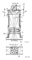
- Fig. 10 ein belichtetes Einzelbild,
- Fig. 11 den Strahlengang und den Längsschnitt eines weiteren Ausführungsbeispieles der erfindungsgemässen Vorrichtung,
- Fig. 12 ein belichtetes Einzelbild,
- Fig. 13 den Strahlengang und den Längsschnitt eines weiteren Ausführungsbeispieles der erfindungsgemässen Vorrichtung, und
- Fig. 14 ein belichtetes Einzelbild.
- 1 shows a section through an annular lens used in an embodiment of the wide-angle optical device according to the invention with a cylindrical outer jacket and a frustoconical inner jacket,
- 2 shows a section through an annular lens with a torodial inner lateral surface,
- 3 shows a section through the ring lens according to FIG. 1 supplemented with a further optical ring, the further ring having a rectangular cross section,
- 4 shows a section through the ring lens according to FIG. 1 and a further plano-concave ring,
- 5 shows a section through the ring lens according to FIG. 1 and a further double-concave ring,
- 6 shows a section through the ring lens according to FIG. 1 and a further plano-convex ring,
- 7 shows a section through the ring lens according to FIG. 1 and a further double convex ring,
- Fig. 8 is a plan view of an embodiment the device according to the invention with a fictitious object cylinder,
- 9 shows the beam path and a longitudinal section of the device according to FIG. 8
- 10 an exposed single image,
- 11 shows the beam path and the longitudinal section of a further exemplary embodiment of the device according to the invention,
- 12 an exposed single image,
- 13 shows the beam path and the longitudinal section of a further exemplary embodiment of the device according to the invention, and
- 14 shows an exposed single image.
Wie es aus der Fig.l ersichtlich ist, weist eine aus Kronglas oder optischem Kunststoff gefertigte Ringlinse 1 nach ihrer Grundform einen zylindrischen äusseren Mantel 2 auf. In Inneren der Ringlinse 1 ist konzentrisch eine optische Öffnung 3 ausgebildet, so dass die Ringlinse 1 einen stumpfkegelförmigen inneren Mantel 7 hat, der einen Winkel von 45° mit dem Vertikalen einschliesst und welcher als optische Spiegelfläche ausgebildet ist. Die Öffnung 3 ist oben durch einen Grundkreis 4 und unten durch einen einem Fotoapparat 5 näher liegenden Spitzenkreis 6 begrenzt. Der Schnitt durch die Ringlinse 1 zeigt, dass diese aus einem Rechteck 8 und einem rechtwinkligen, gleichschenkeligen Dreieck 9 zusamv mengesetzt ist. Der Durchmesser des Spitzenkreises 6 beträgt ein Drittel des Durchmessers der Ringlinse 1.As can be seen from Fig.l, a
Nach dem Ausführungsbeispiel gemäss Fig.2 ist die konzentrische Öffnung 3 im Inneren der Ringlinse 1 so ausgebildet, dass ihr Mantel 7 eine torodiale Fläche statt einer Stumpfkegelform aufweist, wobei der Mantel 7 mit einer Leitkurve dem Grundkreis 4 und dem Spitzenkreis 6 angepasst ist, und die Tangente der Oberfläche schliesst mit der an ihrer Stelle einsetzbaren Stupfkegelfläche in den Kreuzungspunktm einen Winkel von höchstens 3° ein.According to the exemplary embodiment according to FIG. 2, the
In den Figuren 3-7 ist die erfindungsgemässe Ringlinse 1 mit zylindrischem Mantel 2 und verschiedenförmigen zusätzlichen optischen Ringen 11 sichtbar. Die Ringlinse 1 und der jeweilige zusätzliche optische Ring 11 stehen in Klemmverbindung miteinander.FIGS. 3-7 show the
Aus den Figuren 8 und 9 ersichtlicherweise ist die Ringlinse 1 an einer Kante 13 eines Gehäuses 12 durch Kleben befestigt. Das Gehäuse 12 ist ein lichtundurchlässiger Metallzylinder, der an seinem der Ringlinse 1 entgegengesetzten Ende ein Aussengewinde ähnlich wie bei den im Handel erhältlichen Lichtfiltern hat. Dieses Vatergewinde sichert die einfache, lösbare und sichere Verkoppelung der erfindungsgemässen Vorrichtung und des jeweiligen optischen oder fototechnischen Gerätes. Das Gehäuse 12 sichert die Übereinstimmung der optischen Achsen der Ringlinse 1 und eines Objektives 14 des Fotoapparates 5. Die Stirnseite der Ringlinse 1 ist mit einer durch Kleben befestigten und lichtundurchlässigen Abdeckplatte 15 bedeckt. Diese Abdeckplatte 15 verhindert das direkte oder indirekte Eindringen von ungewünschten streustrahlen durch die Ringlinse 1 in das Gehäuse 12 oder in das Objektiv 14. In einer an der Abdeckplatte 15 konzentrisch angeordneten Hülse 16 ist ein Sucherprisma 17 angepasst. Der Querschnitt des Sucherprismas 17 ist mit dem einfachen Hauptschnitt der Ringlinse 1 gleich. An einer Grundplatte 18 und einer Frontplatte 19 ist je ein quaderförmiger Prismenaufsatz 20,21 befestigt, und eine Hinterseite 22 des Sucherprismas 17 schliesst zur dessen optischen Achse einen Winkel von 45° ein, wobei die Hinterseite 22 als eine Spiegelfläche von der Frontplatte 19 her gesehen ausgestaltet ist. Die Hinterseite 22 des Sucherprismas 17 kann auch durch einen Planspiegel ersetzt werden. An der Unterseite der die optische Öffnung 3 der Ringlinse 1 abschliessenden Abdeckplatte 15 ist eine plankonvexe Sammellinse als Korrektionslinse 23 koaxial durch Kleben befestigt. Die Aufgabe der Korrektionslinse 23 ist der Ausgleich der Differenz der Objektweite zwischen der Ringlinse 1 und dem Sucherprisma 17.As can be seen from FIGS. 8 and 9, the
In der Fig. 10 ist ein Einzelbild dargestellt, das mit einem mit der erfindungsgemässen Vorrichtung versehenen Fotoapparat 5 belichtet wurde. Die Lichtstrahlen projizieren die Objektzylinderpunkte von dem Mantel des in einer eingestellten Objektweite t des Fotoapparates 5 liegenden Objektzylinders 25 verkleinert und verzerrt am spiegelnden Mantel 7 der Ringlinse 1, und das Objektiv 14 des Fotoapparates 5 transformiert diese Lichtstrahlen auf den Film 24 auf solcher Weise, dass ein Mittelkreis 28 eines Ringbildes 27 in der Filmebene einem Schnittkreis des Objektzylinders 25 und einer Horizontebene h entspricht, Die Bildpunkte im Ringbild 27 lichten sich vom Mittelkreis 28 nach aussen und verdichten sich vom Mittelkreis 28 zum Mittelpunkt hin. Für die Veränderung der Strahllänge des Objektzylinders 25 dient der herkömmliche Entfernungsversteller den Objektives 14.FIG. 10 shows a single image which was exposed with a
Das Bild der durch das Sucherprisma 17 ausgewählten Objektebene liegt in der Mitte des Einzelbildes im Film 25, wobei die Bildpunkte in einer oder in beiden äufeinander senkrechten liegenden Richtung oder zentralisch geschrumpft sind.The image of the object plane selected by the
In der Fig.11 ist ein Ausführungsbeispiel der erfindungsgemässen weitwinkeligen optischen Vorrichtung sichtbar, in dem eine Ringlinse 1 mit stumpfkegelförmigem inneren Mantel 7 und zylindrischen äusseren Mantel 2 an dem Gehäuse 12 befestigt ist. Ein plankonkaver optischer Ring 11 ist dem Mantel 2 der Ringlinse 1 angeschlössen, dementsprechend ist ein Prismenaufsatz 20 mit einem konkaven zylinderischen Mantel und mit einer zur optischen Achse der Ringlinse 1 senkrecht stehenden Längsachse der Frontplatte 19 des Sucherprismas 17 angepasst. An der Unterseite der Abdeckplatte 15 ist eine plankonvexe Sammellinse als Korrektionslinse 23 geklebt. Die Richtung der Komponente des Objektzylinders 25 stimmt bei der Ringlinse 1 mit konkavem kreisbogenförmigen Mantel 2 mit dem Strahlengang der Ringlinse 1 mit zylindrischem Mantel 2 überein.11 shows an embodiment of the wide-angle optical device according to the invention, in which an
Ein mit der oben dargestellten Vorrichtung belichtetes Einzelbild ist in der Fig.12 sichtbar. Das Bild des Mantels des Objektzylinders 25 erscheint als ein Ringbild 27 auf dem Film 24, wobei ein das Ringbild 27 begrenzender innerer konzentrischer Kreis 29 mit der Abbildung des Spitzenkreises 6 der Ringlinse 1, d.h. mit der Abbildung des Grundkreises des Objektzylinders 25, und ein weiterer das Ringbild 27 begrenzender ausserer konzentrischer Kreis 30 mit der Abbildung des Grundkreises 4 der Ringlinse 1, d.h. mit der Abbildung des Dachkreises des Objektzylinders 25 gleich ist. Bei einer Bildtransformation mit der Ringlinse 1 mit einem konkaven kreisbogenförmigen Mantel 2 entspricht die nach oben zeigende Richtung der Komponente des Objektzylindes 25 der vom Mittelpunkt nach aussen zeigenden Richtung im Ringbild 27 ebenso wie bei der Ringlinse 1 mit zylinderisahem Mantel 2. Der äussere Kreis 30 berührt die Seiten des Einzelbildes auf dem Film 24. Mit der Hilfe eines als Fotozubehör erhältlichen Zwischenringes 26 oder Balges kann die Objektweite t des Objektives 14 so eingestellt werden, dass der äussere Kreis 30 die Ecken des Einzelbildes auf dem Film 24 berührt. In erstbenannten Fall können verschiedene interne Daten, z.B. Belichtungszeit, Blende, Entfernung, eventuelle Nivellierung in den leeren Ecken des Einzelbildes aufgezeichnet werden.A single image exposed with the device shown above is visible in FIG. The image of the jacket of the
In einem weiteren Ausführungsbeispiel der erfindungsgemässen Vorrichtung sind eine Ringlinse 1 mit stumpfkegelfärmigem Mantel 7, und mit einem mit plankonvexem optischen Ring 11 ergänzten zylindrischen Mantel 2, ein Sucherprisma 17 mit einer konvexen kugelförmigen Frontplatte 19 und eine plankonkave Streulinse als Korrektionslinse 23 angeordnet.In a further exemplary embodiment of the device according to the invention, a
Ein mit der oben beschriebenen Vorrichtung belichtetes Einzelbild ist in der Fig.14 sichtbar. Die Richtung der Komponente des Objektzylinders 25 wird durch die einen konvexen kreisbogenförmigen äusseren Mantel 2 habende Ringlinse 1 um 180° umgekehrt, mit dem Strahlengang der Ringlinse 1 mit konkavem kreisbogenförmigen oder zylindrischem Mantel 2 verglichen. An der Aufnahme mit der konvexen kreisbogenförmigen Mantel 2 habenden Ringlinse 1 entspricht die nach oben weisende Richtung der Komponente des Objektzylinders 25 einer im Ringbild 27 zum Mittelpunkt zeigenden Richtung.A single image exposed with the device described above is visible in FIG. 14. The direction of the component of the
Das durch das Sucherprisma 17 übermittelte Bild liegt in der Ebene des Objektzylinders 25, so dass ein auf dem Einzelbild in der Mitte befindliches flaches Bild 31 durch die Scharfeinstellung das Sucherbildes scharf eingestellt werden kann. Das flache Bild 31 kann zur Aufnahme des Hauptmotivs von dem Ringbild 27 unabhängig verwendet werden.That transmitted through the
Die mit einer kontinuierlichen Linie gezeichneten Pfeile in den Figuren stellen die nach oben weisenden Komponente des Objektzylinders 25 und deren Abbildungen auf dem Einzelbild dar. Die mit gestrichelter Linie gezeichneten Pfeile stellen das Gerade der Objektebene des Sucherprismabildes und dessen Abbildung auf dem Einzelbild dar.The arrows drawn with a continuous line in the figures represent the upward-pointing component of the
Durch Umkehren des Strahlenganges kann das durch den mit der erfindungsgemässen Vorrichtung ergänzten Fotoapparat gefertigtes Bild auf einer Kreisleinwand oder einem Kreisfotopapier als Rundbild mit einem aus einer Lichtquelle, einem Parabelspiegel und einer Sammellinse bestehenden Projektor dargestellt werden. Die Projektionsentfernung, das Verhältnis der Höhe und des Umfanges des Rundbildes kann durch die Korrektion des Brennpunktes und der Strahlenlänge der Brennweite verändert werden. Das flache Bild 31 kann durch das Sucherprisma 17 auf eine Leinwand oder ein Fotopapier projektiert werden. In diesem Fall ist die Ringlinse 1 auch an ihrem Mantel 2 abgedeckt und das projektierte Bild weist eine Normalgrösse oder eine Panoramagrösse abhängig von der Front- 'plattengestaltung des Sucherprismas 17 auf.By reversing the beam path, the image produced by the camera supplemented with the device according to the invention can be displayed on a circular screen or a circular photographic paper as a circular image with a projector consisting of a light source, a parabolic mirror and a converging lens. The projection distance, the ratio of the height and the circumference of the circular image can be changed by correcting the focal point and the beam length of the focal length. The flat image 31 can be projected through the
Die erfindungsgemässe Vorrichtung kann an Fotoapparaten, Filmkameras, FS-Fameras, Videokameras, an optischen Instrumenten und Geräten sowie an Bildprojektoren angeschlossen werden.The device according to the invention can be connected to cameras, film cameras, FS cameras, video cameras, to optical instruments and devices and to image projectors.
Die Vorrichtung kann zur Prüfung von Selbstschwingungen von dreidimensionalen Baukonstruktionen verwendet werden. An einer Seite der in einer zur Horizontebene senkrecht liegenden Ebene schwingenden kritischen Baukonstruktion sollen flimmernde Streifen geklebt werden und Stimmgabel bekannter Schwingungszahlen sollen in der Nähe der Stelle des Höchstausschlages zur Schwingungsebene parallel angeordnet werden. Das Sucherprisma wird an die Stimmgabel gerichtet und gleichzeitig werden diese und die Baukonstruktion in Schwingung gebracht. Nach der Aufnahme des Rundbildes verändert sich die Bildfarbvalenz der schwingenden Elemente im Ringbild 27 und im flachen Bild 31 im Zusammenhang mit der Schwingungszahl. Nach der Vergrösserung oder der Projektion des positiven Bildes kann die Schwingungszahl der Stimmgabel mit der Schwingungszahl des Bauelementes verglichen und die Selbstschwingungszahl der Baukonstruktion und der damit gekoppelten Konstruktionsteile durch Interpolation festgestellt werden. Im Kenntnis der Selbstschwingungszahl kann die ideale Selbstschwingungszahl oder der Dynamikfaktor der 3aukonstruktion durch Veränderung der Spannweite und der Kasse eingestellt werden.The device can be used to test self-vibrations of three-dimensional building structures. Flickering strips are to be glued to one side of the critical building structure vibrating in a plane perpendicular to the horizontal plane, and tuning forks of known vibration numbers are to be arranged parallel to the vibration level in the vicinity of the point of maximum deflection. The finder prism is aimed at the tuning fork and at the same time this and the building structure are vibrated. After the round image has been recorded, the image color valence of the vibrating elements in the
Nach einer Weiterentwicklung der obigen Prüfung werden mehrere flimmernden Punkte an der Baukonstruktion aufgeklebt und mit der Aufnahme gleichzeitig wird der Film 24 in seiner Ebene um seine optische Achse stationär verdreht. Das Bild des flimmernden Punktes erscheint in der Form eines Schwingunsgrafikons in dem Ringbild 27 und im flachen Bild 31.After a further development of the above test, several flickering points are glued to the building structure and, with the recording, the
Es kann als Vorteil der erfindungsgemässen weitwinkeligen optischen Vorrichtung bezeichnet werden, dass ihr horizontaler Sichtwinkel 360° beträgt und vertikaler Sichtwinkel zwischen 0°-84° liegt, und mit jedwelchem bekannten optischen oder fototechnischen Gerät gekoppelt werden kann.It can be described as an advantage of the wide-angle optical device according to the invention that their horizontal viewing angle is 360 ° and vertical viewing angle is between 0 ° -84 °, and can be coupled with any known optical or photo-technical device.
Die Erfindung enthält weitere Merkmale, die nachstehend in Anspruchsform wiedergegeben werden.The invention contains further features which are reproduced below in the form of claims.
-
11. Vorrichtung nach Anspruch 8, dadurch gekennzeichnet , dass der Ring (11) einen plankonvexen Querschnitt hat.11. The device according to
claim 8, characterized in that the ring (11) has a plano-convex cross section. -
12. Vorrichtung nach Anspruch 8, dadurch gekennzeichnet , dass der Ring (11) einen doppelkonkaven Querschnitt hat.12. The apparatus according to
claim 8, characterized in that the ring (11) has a double concave cross section. -
13. Vorrichtung nach Anspruch 8, dadurch gekennzeichnet , dass der Ring (11) einen doppelkonvexen Querschnitt hat.13. The apparatus according to
claim 8, characterized in that the ring (11) has a double convex cross section. - 14. Vorrichtung nach einem der Ansprüche 1-13, dadurch gekennzeichnet, dass ein Suoherprisma (17) an der Aussenseite der Abdeckplatte (15) und eine Korrektionslinse (23) an der Innenseite der Abdeckplatte (15) koaxial zur Ringlinse (1) angeordnet ist.14. Device according to one of claims 1-13, characterized in that a Suoher prism (17) on the outside of the cover plate (15) and a correction lens (23) on the inside of the cover plate (15) is arranged coaxially to the ring lens (1) .
-
15. Vorrichtung nach Anspruch 14, dadurch gekennzeichnet , dass 'das Sucherprisma (17) an der Abdeckplatte (15) um ihre optische Achse frei drehbar angeordnet ist.15. The apparatus according to
claim 14, characterized in that 'the viewfinder prism (17) on the cover plate (15) is arranged freely rotatable about its optical axis. - 16. Vorrichtung nach Anspruch 14 oder 15, dadurch gekennzeichnet, dass ein quarderförmiger oder zylinderförmiger Prismenaufsatz (20,21) an einer Grundplatte (18) und einer Frontplatte (19) des Sucherprismas (17) angeschlossen ist,dessen einen Winkel von 45 zur optischen Achse einschliessende Hinterseite (22) als eine Spiegelfläche von der Frontplatte (19) her gesehen ausgestaltet ist.16. The apparatus according to claim 14 or 15, characterized in that a a square or cylindrical prism attachment (20, 21) is connected to a base plate (18) and a front plate (19) of the finder prism (17), the rear side (22) of which includes an angle of 45 to the optical axis as a mirror surface of the front plate (19 seen here is designed.
- 17. Vorrichtung nach einem der Ansprüche 14-16, dadurch gekennzeichnet, dass die Frontplatte (19) des Sucherprismas (17) ein konkaver bzw. konvexer Zylindermantel mit einer zur optischen Achse der Ringlinse (1) querstehenden oder parallellen Längsachse ist.17. Device according to one of claims 14-16, characterized in that the front plate (19) of the finder prism (17) is a concave or convex cylinder jacket with a longitudinal axis transverse or parallel to the optical axis of the ring lens (1).
- 18. Vorrichtung nach einem der Ansprüche 14-16, dadurch gekennzeichnet, dass die Frontplatte (19) des Sucherprismas (17) eine konkave bzw. konvexe Kugelfläche mit einem zur optischen Achse der Ringlinse (1) senkrecht stehenden Radius ist.18. Device according to one of claims 14-16, characterized in that the front plate (19) of the finder prism (17) is a concave or convex spherical surface with a radius perpendicular to the optical axis of the ring lens (1).
-
19. Vorrichtung nach Anspruch 14, dadurch gekennzeichnet , dass die Korrektionslinse (23) eine plankonvexe Sammellinse ist.19. The apparatus according to
claim 14, characterized in that the correction lens (23) is a plano-convex converging lens. -
20. Vorrichtung nach Anspruch 14, dadurch gekennzeichnet , dass die Korrektionslinse (23) eine plankonkave Sammellinse ist.20. The apparatus according to
claim 14, characterized in that the correction lens (23) is a plano-concave converging lens. - 21. Vorrichtung nach einem der Ansprüche 1-20, dadurch gekennzeichnet, dass die Ringlinse (1), der optische Ring (11) und das Sucherprisma (17) aus Kronglas gefertigt sind.21. Device according to one of claims 1-20, characterized in that the ring lens (1), the optical ring (11) and the finder prism (17) are made of crown glass.
- 22. Vorrichtung nach einem der Ansprüche 1-20, dadurch gekennzeichnet, dass die Ringlinse (1), der optische Ring (11) und das Sucherprisma (17) aus optischem Kunststoff gefertigt sind.22. Device according to one of claims 1-20, characterized in that the ring lens (1), the optical ring (11) and the finder prism (17) are made of optical plastic.
- 1 Ringlinse1 ring lens
- 2 Mantel2 coat
- 3 Öffnung3 opening
- 4 Grundkreis4 base circle
- 5 Fotoapparat5 camera
- 6 Spitzenkreis6 top circle
- 7 Mantel7 coat
- 8 Rechteck8 rectangle
- 9 Dreieck9 triangle
- 11 Ring11 ring
- 12 Gehäuse12 housing
- 13 Kante13 edge
- 14 Objektiv14 lens
- 15 Abdeckplatte15 cover plate
- 16 Hülse16 sleeve
- 17 Sucherprisma17 viewfinder prism
- 18 Grundplatte18 base plate
- 19 Stirnplatte19 end plate
- 20 Prismenaufsatz20 prism attachment
- 21 Prismenaufsatz21 prism attachment
- 22 Hinterseite22 rear
- 23 Korrektionslinse23 correction lens
- 24 Film24 film
- 25 Objektzylinder25 object cylinders
- 26 Zwischenring26 intermediate ring
- 27 Ringbild27 ring pattern
- 28 Mittelkreis28 center circle
- 29 Kreis29 circle
- 30 Kreis30 circle
- 31 Bild31 picture
- α Winkelα angle
- Δt DifferenzΔt difference
- t Objektweitet object width
- k Bildweitek image width
- h Horizontebeneh horizon level
Claims (10)
Priority Applications (1)
| Application Number | Priority Date | Filing Date | Title |
|---|---|---|---|
| AT83109036T ATE24780T1 (en) | 1982-09-14 | 1983-09-13 | WIDE ANGLE OPTICAL DEVICE. |
Applications Claiming Priority (2)
| Application Number | Priority Date | Filing Date | Title |
|---|---|---|---|
| HU822921A HU193030B (en) | 1982-09-14 | 1982-09-14 | Optical instrument of wide visual angle |
| HU292182 | 1982-09-14 |
Publications (3)
| Publication Number | Publication Date |
|---|---|
| EP0103301A2 true EP0103301A2 (en) | 1984-03-21 |
| EP0103301A3 EP0103301A3 (en) | 1984-09-05 |
| EP0103301B1 EP0103301B1 (en) | 1987-01-07 |
Family
ID=10961687
Family Applications (1)
| Application Number | Title | Priority Date | Filing Date |
|---|---|---|---|
| EP83109036A Expired EP0103301B1 (en) | 1982-09-14 | 1983-09-13 | Wide-angle optical device |
Country Status (7)
| Country | Link |
|---|---|
| EP (1) | EP0103301B1 (en) |
| JP (1) | JPS59140442A (en) |
| AT (1) | ATE24780T1 (en) |
| CS (1) | CS250234B2 (en) |
| DD (1) | DD214221A5 (en) |
| DE (1) | DE3369010D1 (en) |
| HU (1) | HU193030B (en) |
Cited By (7)
| Publication number | Priority date | Publication date | Assignee | Title |
|---|---|---|---|---|
| US4900914A (en) * | 1987-05-27 | 1990-02-13 | Carl-Zeiss-Stiftung | Wide-angle viewing window with a plurality of optical structures |
| EP0671613A1 (en) * | 1994-03-09 | 1995-09-13 | TEMIC TELEFUNKEN microelectronic GmbH | Optical system |
| EP0766112A2 (en) * | 1995-09-26 | 1997-04-02 | Rockwell International Corporation | Panoramic optics assembly having an initial flat reflective element |
| EP0816891A1 (en) * | 1996-06-27 | 1998-01-07 | HE HOLDINGS, INC. dba HUGHES ELECTRONICS | Integrated panoramic and high resolution sensor optics |
| US6082869A (en) * | 1999-04-01 | 2000-07-04 | Draheim; Jon M | Door/window mounted safety mirror |
| EP1440562A2 (en) * | 2001-09-18 | 2004-07-28 | Wave Group Ltd. | Panoramic imaging system with optical zoom capability |
| US7034999B1 (en) | 1998-09-29 | 2006-04-25 | Casler Christopher L | Hemispheric lens for a remote-controlled retail electronic entertainment device |
Families Citing this family (5)
| Publication number | Priority date | Publication date | Assignee | Title |
|---|---|---|---|---|
| JPH02151828A (en) * | 1988-12-02 | 1990-06-11 | Mitsubishi Electric Corp | All-azimuth observation device |
| US4973113A (en) * | 1989-04-20 | 1990-11-27 | E. I. Du Pont De Nemours And Company | Method and apparatus for making transmission holograms |
| TW198748B (en) * | 1990-02-20 | 1993-01-21 | Hughes Aircraft Co | |
| DE102010041490A1 (en) * | 2010-09-27 | 2012-03-29 | Carl Zeiss Microimaging Gmbh | Optical instrument and method for optical monitoring |
| DE102012215624B3 (en) * | 2012-09-04 | 2014-02-27 | FoxyLED GmbH | Optical arrangement |
Citations (4)
| Publication number | Priority date | Publication date | Assignee | Title |
|---|---|---|---|---|
| FR338386A (en) * | 1903-03-21 | 1904-05-17 | Francois Fernand Bourdil | Animated panoramic image production system |
| US2304434A (en) * | 1928-09-03 | 1942-12-08 | Ibm | Projecting device |
| GB1026870A (en) * | 1963-06-06 | 1966-04-20 | Akinwunmi Adegboye | Improvements in or relating to panoramic cine cameras |
| GB1493188A (en) * | 1975-04-22 | 1977-11-23 | Anderson H | Optic for instantaneously photographing an horizon of 360 degree |
-
1982
- 1982-09-14 HU HU822921A patent/HU193030B/en not_active IP Right Cessation
-
1983
- 1983-09-13 AT AT83109036T patent/ATE24780T1/en not_active IP Right Cessation
- 1983-09-13 EP EP83109036A patent/EP0103301B1/en not_active Expired
- 1983-09-13 DE DE8383109036T patent/DE3369010D1/en not_active Expired
- 1983-09-14 DD DD83254824A patent/DD214221A5/en unknown
- 1983-09-14 CS CS836696A patent/CS250234B2/en unknown
- 1983-09-14 JP JP58168495A patent/JPS59140442A/en active Pending
Patent Citations (4)
| Publication number | Priority date | Publication date | Assignee | Title |
|---|---|---|---|---|
| FR338386A (en) * | 1903-03-21 | 1904-05-17 | Francois Fernand Bourdil | Animated panoramic image production system |
| US2304434A (en) * | 1928-09-03 | 1942-12-08 | Ibm | Projecting device |
| GB1026870A (en) * | 1963-06-06 | 1966-04-20 | Akinwunmi Adegboye | Improvements in or relating to panoramic cine cameras |
| GB1493188A (en) * | 1975-04-22 | 1977-11-23 | Anderson H | Optic for instantaneously photographing an horizon of 360 degree |
Cited By (9)
| Publication number | Priority date | Publication date | Assignee | Title |
|---|---|---|---|---|
| US4900914A (en) * | 1987-05-27 | 1990-02-13 | Carl-Zeiss-Stiftung | Wide-angle viewing window with a plurality of optical structures |
| EP0671613A1 (en) * | 1994-03-09 | 1995-09-13 | TEMIC TELEFUNKEN microelectronic GmbH | Optical system |
| EP0766112A2 (en) * | 1995-09-26 | 1997-04-02 | Rockwell International Corporation | Panoramic optics assembly having an initial flat reflective element |
| EP0766112A3 (en) * | 1995-09-26 | 1998-04-01 | Rockwell International Corporation | Panoramic optics assembly having an initial flat reflective element |
| EP0816891A1 (en) * | 1996-06-27 | 1998-01-07 | HE HOLDINGS, INC. dba HUGHES ELECTRONICS | Integrated panoramic and high resolution sensor optics |
| US7034999B1 (en) | 1998-09-29 | 2006-04-25 | Casler Christopher L | Hemispheric lens for a remote-controlled retail electronic entertainment device |
| US6082869A (en) * | 1999-04-01 | 2000-07-04 | Draheim; Jon M | Door/window mounted safety mirror |
| EP1440562A2 (en) * | 2001-09-18 | 2004-07-28 | Wave Group Ltd. | Panoramic imaging system with optical zoom capability |
| EP1440562A4 (en) * | 2001-09-18 | 2009-05-06 | Wave Group Ltd | Panoramic imaging system with optical zoom capability |
Also Published As
| Publication number | Publication date |
|---|---|
| ATE24780T1 (en) | 1987-01-15 |
| DD214221A5 (en) | 1984-10-03 |
| HU193030B (en) | 1987-08-28 |
| JPS59140442A (en) | 1984-08-11 |
| CS250234B2 (en) | 1987-04-16 |
| EP0103301B1 (en) | 1987-01-07 |
| EP0103301A3 (en) | 1984-09-05 |
| DE3369010D1 (en) | 1987-02-12 |
Similar Documents
| Publication | Publication Date | Title |
|---|---|---|
| DE19832317C1 (en) | Arrangement in which light is directed onto a surface from a light source | |
| DE19635666C1 (en) | Integrated microscope apparatus | |
| DE69727052T2 (en) | OMNIDIRECTIONAL IMAGING DEVICE | |
| DE602004003305T2 (en) | image viewer | |
| DE19851000C2 (en) | Projection arrangement | |
| DE3020171C2 (en) | Viewfinder device for a television camera | |
| EP0103301B1 (en) | Wide-angle optical device | |
| DE19948542A1 (en) | Arrangement in which light is directed onto a surface from a light source | |
| DE2645187C2 (en) | Television camera | |
| DE2602967A1 (en) | METHOD FOR CAPTURING OR PROJECTING A PANORAMIC VIEW AND DEVICE FOR IMPLEMENTING THE SAME | |
| DE2240746A1 (en) | OPTICAL IMAGING DEVICE | |
| DE1937933A1 (en) | Optical converter for converting a perspective photograph of a spherical body into a plane projection | |
| DE2611971A1 (en) | OPTICAL DEVICE FOR TRANSFERRING LIGHT OR VIEWING AN IMAGE | |
| US2430121A (en) | Optical system for color photography | |
| EP1754106B1 (en) | Device for blending information into the finder beam path of a motion picture camera | |
| DE19907345A1 (en) | Raster image display device for computer screen, includes arrangement for centralizing image at output of projection optics | |
| DE2217156A1 (en) | METHOD OF RECORDING AND REPLAYING IMAGES | |
| EP0285907B1 (en) | Electophotographic copying device | |
| DE677812C (en) | Method and device for cinematography using a lenticular lens | |
| DE2316273C3 (en) | Method and device for reducing contrast in reproduction | |
| DE1814693C (en) | Single lens reflex camera with microphotometric control | |
| DE60310563T2 (en) | Improvements to an image projector | |
| DE1597409C (en) | Color television camera | |
| DE616298C (en) | Photographic camera with setting viewfinder | |
| AT223465B (en) | Single lens reflex camera |
Legal Events
| Date | Code | Title | Description |
|---|---|---|---|
| PUAI | Public reference made under article 153(3) epc to a published international application that has entered the european phase |
Free format text: ORIGINAL CODE: 0009012 |
|
| AK | Designated contracting states |
Designated state(s): AT BE CH DE FR GB IT LI LU NL SE |
|
| PUAL | Search report despatched |
Free format text: ORIGINAL CODE: 0009013 |
|
| AK | Designated contracting states |
Designated state(s): AT BE CH DE FR GB IT LI LU NL SE |
|
| 17P | Request for examination filed |
Effective date: 19840928 |
|
| GRAA | (expected) grant |
Free format text: ORIGINAL CODE: 0009210 |
|
| AK | Designated contracting states |
Kind code of ref document: B1 Designated state(s): AT BE CH DE FR GB IT LI LU NL SE |
|
| PG25 | Lapsed in a contracting state [announced via postgrant information from national office to epo] |
Ref country code: NL Effective date: 19870107 Ref country code: IT Free format text: LAPSE BECAUSE OF FAILURE TO SUBMIT A TRANSLATION OF THE DESCRIPTION OR TO PAY THE FEE WITHIN THE PRESCRIBED TIME-LIMIT;WARNING: LAPSES OF ITALIAN PATENTS WITH EFFECTIVE DATE BEFORE 2007 MAY HAVE OCCURRED AT ANY TIME BEFORE 2007. THE CORRECT EFFECTIVE DATE MAY BE DIFFERENT FROM THE ONE RECORDED. Effective date: 19870107 |
|
| REF | Corresponds to: |
Ref document number: 24780 Country of ref document: AT Date of ref document: 19870115 Kind code of ref document: T |
|
| REF | Corresponds to: |
Ref document number: 3369010 Country of ref document: DE Date of ref document: 19870212 |
|
| ET | Fr: translation filed | ||
| NLV1 | Nl: lapsed or annulled due to failure to fulfill the requirements of art. 29p and 29m of the patents act | ||
| PG25 | Lapsed in a contracting state [announced via postgrant information from national office to epo] |
Ref country code: LU Free format text: LAPSE BECAUSE OF NON-PAYMENT OF DUE FEES Effective date: 19870930 |
|
| PLBE | No opposition filed within time limit |
Free format text: ORIGINAL CODE: 0009261 |
|
| STAA | Information on the status of an ep patent application or granted ep patent |
Free format text: STATUS: NO OPPOSITION FILED WITHIN TIME LIMIT |
|
| 26N | No opposition filed | ||
| PG25 | Lapsed in a contracting state [announced via postgrant information from national office to epo] |
Ref country code: GB Effective date: 19880913 Ref country code: AT Effective date: 19880913 |
|
| PG25 | Lapsed in a contracting state [announced via postgrant information from national office to epo] |
Ref country code: SE Effective date: 19880914 |
|
| PG25 | Lapsed in a contracting state [announced via postgrant information from national office to epo] |
Ref country code: LI Effective date: 19880930 Ref country code: CH Effective date: 19880930 Ref country code: BE Effective date: 19880930 |
|
| BERE | Be: lapsed |
Owner name: KOZPONTI VALTO-ES HITELBANK RC Effective date: 19880930 |
|
| PG25 | Lapsed in a contracting state [announced via postgrant information from national office to epo] |
Ref country code: FR Free format text: LAPSE BECAUSE OF NON-PAYMENT OF DUE FEES Effective date: 19890531 |
|
| REG | Reference to a national code |
Ref country code: CH Ref legal event code: PL |
|
| GBPC | Gb: european patent ceased through non-payment of renewal fee | ||
| PG25 | Lapsed in a contracting state [announced via postgrant information from national office to epo] |
Ref country code: DE Effective date: 19890601 |
|
| REG | Reference to a national code |
Ref country code: FR Ref legal event code: ST |
|
| EUG | Se: european patent has lapsed |
Ref document number: 83109036.0 Effective date: 19890712 |