EP0103042B1 - Fan comprising automatically adjustable blades about its longitudinal axis to avoid undesirable rotational speed - Google Patents
Fan comprising automatically adjustable blades about its longitudinal axis to avoid undesirable rotational speed Download PDFInfo
- Publication number
- EP0103042B1 EP0103042B1 EP82108470A EP82108470A EP0103042B1 EP 0103042 B1 EP0103042 B1 EP 0103042B1 EP 82108470 A EP82108470 A EP 82108470A EP 82108470 A EP82108470 A EP 82108470A EP 0103042 B1 EP0103042 B1 EP 0103042B1
- Authority
- EP
- European Patent Office
- Prior art keywords
- blades
- fan
- impeller hub
- stop means
- remaining
- Prior art date
- Legal status (The legal status is an assumption and is not a legal conclusion. Google has not performed a legal analysis and makes no representation as to the accuracy of the status listed.)
- Expired
Links
Images

Classifications
-
- F—MECHANICAL ENGINEERING; LIGHTING; HEATING; WEAPONS; BLASTING
- F04—POSITIVE - DISPLACEMENT MACHINES FOR LIQUIDS; PUMPS FOR LIQUIDS OR ELASTIC FLUIDS
- F04D—NON-POSITIVE-DISPLACEMENT PUMPS
- F04D29/00—Details, component parts, or accessories
- F04D29/26—Rotors specially for elastic fluids
- F04D29/32—Rotors specially for elastic fluids for axial flow pumps
- F04D29/34—Blade mountings
- F04D29/36—Blade mountings adjustable
- F04D29/362—Blade mountings adjustable during rotation
- F04D29/366—Adjustment by interaction of inertion and lift
-
- F—MECHANICAL ENGINEERING; LIGHTING; HEATING; WEAPONS; BLASTING
- F04—POSITIVE - DISPLACEMENT MACHINES FOR LIQUIDS; PUMPS FOR LIQUIDS OR ELASTIC FLUIDS
- F04D—NON-POSITIVE-DISPLACEMENT PUMPS
- F04D27/00—Control, e.g. regulation, of pumps, pumping installations or pumping systems specially adapted for elastic fluids
- F04D27/002—Control, e.g. regulation, of pumps, pumping installations or pumping systems specially adapted for elastic fluids by varying geometry within the pumps, e.g. by adjusting vanes
Definitions
- the invention relates to a fan with blades which can be rotated automatically about a longitudinal axis in order to avoid undesired rotational speeds according to the preamble of patent claim 1 and of patent claim 3; such a fan is known from DE-A-862 280 and FR-A-1 553 046.
- the blades of the variable-pitch propeller are adjusted in a speed-dependent manner by centrifugal force regulators in order to achieve a starting position in a particularly simple manner in such a way that they are brought to a steeper position and thus a smaller angle with respect to the wind direction when the vehicle is at a standstill and at very low speeds will.
- the centrifugal forces work on the respective wing axis via transmission means.
- the centrifugal force device is to be used both for the adjustment in the start-up area and in the work area.
- the known device is considered particularly advantageous for the use of wind power motors for small systems, since the propeller can start with large moments on the one hand and, on the other hand, as a high-speed runner in the actual working area of the impeller, it can be adjusted automatically as a function of speed in such a way that a control to an approximately constant speed or results in consistent performance.
- the aim is to ensure that a generator connected to a wind turbine is no longer supplied with additional energy from a certain wind speed.
- the wind turbines which operate continuously in turbine operation, they are first pulled against a stop with a spring; depending on the wind speed and in particular on the setting or the force of the spring, the wing lifts off the stop during operation, so that the aerodynamic angle of attack increases.
- a weight arranged downstream on the wing is provided in order to reduce the angle of attack due to special inertia effects when the wind turbine accelerates.
- the object of the present invention is to protect the fan from a harmful increase in speed in the event of a malfunction in the event of an external pressure wave driving the fan while maintaining its direction of rotation according to the principle of a wind turbine by the flow forces occurring in the pressure wave.
- a fault is to be considered in particular when the secured secondary cooling circuit of a power plant block, consisting of cell coolers with a fan, must also be designed against the "external explosion" load case.
- the explosion pressure wave is idealized by a pressure-time function, which among other things is characterized by a short but very high pressure increase or speed increase at the beginning of the start of the pressure wave. If the safety design of the fan provided in accordance with the task were not present, the pressure wave that would start would cause the operating speed of the fan to rise to such a peak speed that even materials with a large tear length could not withstand this load.
- the counterweights in cooperation with the blades adjustable about their special longitudinal axes and the acting air and centrifugal forces ensure that the adjustable blades on the one hand in normal operation in accordance with the teaching of claim 1
- Design provided by the centrifugal force is not rotated in the closed position with the wing chord running almost perpendicular to the fan axis, but pressed against the first stop or, in the case of the design provided for in claim 3, is pressed against the first stop with moderate force that can be overcome in the event of a fault, and on the other hand
- the triggering criterion of the reversal of the resulting air force characteristic of the transition from pump to turbine operation, tilts from its first operating position into the second malfunctioning position and, in this, an undesirable rotation increase avoiding position can be held either by the second stop or in the zero-lift equilibrium position without a separate stop.
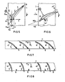
- every second wing 2 is alternately designed as an independently rotatable wing 3, while the remaining wings 2 are arranged fixedly on the circumference of the impeller hub 1.
- 4 shows, in a partial section, a top view of a developed impeller hub 1, two vanes 2 fixedly arranged on the circumference of this impeller hub and two vanes 3, each of which rotates along its longitudinal axis 31.
- the rotatable vanes 3 are entered in FIG. in which they abut against stops 7 with their upstream ends.
- the rotatable wings 3 are pivoted about their longitudinal axis 31 in such a way that their downstream ends rest against stops 6 and one to the fixed wings 2 take up the equivalent wing position.
- the centrifugal weights fixedly arranged on the rotatable wings 3 according to the invention are not shown in FIG. 4.
- FIG. 1 shows a sectional view of a single wing 3, which in the normal operating position due to the assumed direction of rotation: n or flow direction: L of the air, the bearing in the axis of gravity 31 and the counterweight 5 shown with its outflow end against the first Stop 6 is pressed.
- the counterweights 5 compensate for the influence of the centrifugal forces, which otherwise try to turn the rotatable blades in the closed position (wing chord perpendicular to the impeller axis) and, on the other hand, achieve that the rotating blades with a definable pressure against the stop also when starting the impeller 6 are pressed.
- the counterweights are each arranged in the quadrant of an assumed coordinate system, the coordinate origin of which according to FIG. 1 lies in the center of gravity of the longitudinal axis 31 and the abscissa x in the directions of rotation of the impeller or the ordinate y thereof in the direction L of the air flow.
- Fig. 1 the resulting air force F, which acts on the vane 3 in normal fan operation, is also entered, which is due to the entered speed triangle with the assumed speeds: passage speed c m circumferential speed u and the relative or inflow speed w (neglecting the behind Impeller existing swirl component) results in the wing-fixed coordinate system.
- FIGS. 5 to 8 show a further embodiment of a pressure-resistant axial fan designed according to the invention with the direction of rotation again assumed: n and the direction of flow: L of the air.
- all vanes 4 arranged on the circumference of the impeller hub 1 are rotatably mounted. The rotation takes place about a longitudinal axis 41 in the first quarter of the wing depth.
- Each wing is in turn firmly connected to a counterweight 5 arranged in the upstream region of the impeller hub 1 according to FIGS. 5 and 6.
- the counterweights 5 are not shown in the schematic development of the impeller hub 1 according to FIG. 7 or FIG. 8.
- each blade 4 is in normal fan operation due to the interaction of the air and centrifugal forces at its output end in the start-up or Operating position pressed against a first stop ⁇ .
- Each individual wing will adjust in the intended bearing in the direction of zero lift if the air force F 2 changes its sign after the impact of the pressure wave and acts on the wing according to FIG. 6.
- the air force causes each wing to bear against its stop 8.
- the undesired adjusting torque acting on the wing during operation due to centrifugal forces is in turn compensated by counterweights 5.
- the counterweight is in turn arranged in quadrant 111 of an assumed coordinate system, the coordinate origin of which lies at the point of the longitudinal axis 41 and the abscissa x in the direction of rotation n and the ordinate thereof in the direction of the air flow.
- the counterweight 5 is dimensioned in the sense of the invention so that, on the one hand, in normal operation, in particular in start-up operation, a wing system with a defined pressure on the stop 8 is ensured and, in the event of a malfunction, the relatively low air force can tip the wing into the zero lift position.
- Fig. 7 shows in a partial development of the impeller hub 1, the operating position of the vanes 4 with the assumed assumed direction of rotation n of the impeller and the inflow direction L of the pressure wave.
- 8 shows the same development of the impeller hub, however, with vanes 4 rotated about their respective longitudinal axis 41 in the zero lift direction and with neglected bearing friction in each case.
Abstract
Description
Die Erfindung bezieht sich auf einen Ventilator mit zur Vermeidung unerwünschter Drehzahlen selbsttätig um eine Längsachse drehbaren Flügeln gemäß Oberbegriff des Patentanspruchs 1 bzw. des Patentanspruchs 3; ein derartiger Ventilator ist aus der DE-A-862 280 bzw. der FR-A-1 553 046 bekannt.The invention relates to a fan with blades which can be rotated automatically about a longitudinal axis in order to avoid undesired rotational speeds according to the preamble of
Bei dem durch die DE-A-862 280 bekannten Ventilator werden die Flügel des Verstellpropellers zur besonders einfachen Erzielung einer Anfahrstellung drehzahlabhängig mittels Fliehkraftreglern derart verstellt, daß sie bei Stillstand und sehr geringen Drehzahlen in eine steilere Stellung und somit einen kleineren Winkel gegenüber der Windrichtung gebracht werden. Die Fliehkräfte arbeiten dabei über Übertragungsmittel auf die jeweilige Flügelachse. Nach einer Ausgestaltung der Erfindung soll die Fliehkrafteinrichtung sowohl für die Verstellung im Anlaufbereich als auch im Arbeitsbereich verwendet werden. Die bekannte Einrichtung wird besonders vorteilhaft für die Verwendung von Windkraftmotoren für kleine Anlagen angesehen, da der Propeller einerseits mit großen Momenten anlaufen kann und andererseits als Schnell-Läufer im eigentlichen Arbeitsbereich des Flügelrades selbsttätig drehzahlabhängig derart verstellbar ist, daß sich eine Regelung auf annähernd gleichbleibende Drehzahl oder auf gleichbleibende Leistung ergibt.In the fan known from DE-A-862 280, the blades of the variable-pitch propeller are adjusted in a speed-dependent manner by centrifugal force regulators in order to achieve a starting position in a particularly simple manner in such a way that they are brought to a steeper position and thus a smaller angle with respect to the wind direction when the vehicle is at a standstill and at very low speeds will. The centrifugal forces work on the respective wing axis via transmission means. According to one embodiment of the invention, the centrifugal force device is to be used both for the adjustment in the start-up area and in the work area. The known device is considered particularly advantageous for the use of wind power motors for small systems, since the propeller can start with large moments on the one hand and, on the other hand, as a high-speed runner in the actual working area of the impeller, it can be adjusted automatically as a function of speed in such a way that a control to an approximately constant speed or results in consistent performance.
Im Falle der FR-A-1 553 046 soll erreicht werden, daß einem mit einem Windrad verbundenen Generator ab einer bestimmten Windgeschwindigkeit keine zusätzliche Energie mehr zugeführt wird. Zur Leistungsbegrenzung der dauernd im Turbinenbetrieb arbeitenden Windräder werden diese mit einer Feder zunächst gegen einen Anschlag gezogen; abhängig von der Windgeschwindigkeit und insbesondere von der Einstellung bzw. der Kraft der Feder hebt der Flügel im Betrieb von dem Anschlag ab, so daß sich der aerodynamische Anstellwinkel vergrößert. Eine stromabwärts am Flügel angeordnetes Gewicht ist vorgesehen, um bei einer Beschleunigung des Windrades den Anstellwinkel wegen besonderer Trägheitseffekte zu verkleinern.In the case of FR-A-1 553 046, the aim is to ensure that a generator connected to a wind turbine is no longer supplied with additional energy from a certain wind speed. In order to limit the power of the wind turbines, which operate continuously in turbine operation, they are first pulled against a stop with a spring; depending on the wind speed and in particular on the setting or the force of the spring, the wing lifts off the stop during operation, so that the aerodynamic angle of attack increases. A weight arranged downstream on the wing is provided in order to reduce the angle of attack due to special inertia effects when the wind turbine accelerates.
Der vorliegenden Erfindung liegt die Aufgabe zugrunde, mit einfachen Mitteln den Ventilator vor einer schädlichen Drehzahlerhöhung im Störfall einer externen, den Ventilator unter Beibehaltung seiner Drehrichtung nach dem Prinzip einer Windturbine antreibenden Druckwelle durch die in der Druckwelle auftretenden Strömungskräfte zu schützen. Ein solcher Störfall ist insbesondere dann zu betrachten, wenn der gesicherte Nebenkühlkreis eines Kraftwerkblocks, bestehend aus Zellenkühlern mit Ventilator, auch gegen den Lastfall "äußere Explosion" auszulegen ist. Nach den Vorschriften der Genehmigungsbehörden ist die Explosionsdruckwelle durch eine Druck-ZeitFunktion zu idealisieren, die u.a. durch eine kurzzeitige, jedoch sehr hohen Druckanstieg bzw. Geschwindigkeitsanstieg zu Begin der anlaufenden Druckwelle gekennzeichnet ist. Wäre eine aufgabengemäß vorgesehene Sicherheitskonstruktion des Ventilators nicht vorhanden, so würde gegebenenfalls die anlaufende Druckwelle die Betriebsdrehzahl des Ventilators auf eine solche Spitzendrehzahl ansteigen lassen, daß selbst Werkstoffe großer Reißlänge dieser Belastung nicht widerstehen könnten.The object of the present invention is to protect the fan from a harmful increase in speed in the event of a malfunction in the event of an external pressure wave driving the fan while maintaining its direction of rotation according to the principle of a wind turbine by the flow forces occurring in the pressure wave. Such a fault is to be considered in particular when the secured secondary cooling circuit of a power plant block, consisting of cell coolers with a fan, must also be designed against the "external explosion" load case. According to the regulations of the licensing authorities, the explosion pressure wave is idealized by a pressure-time function, which among other things is characterized by a short but very high pressure increase or speed increase at the beginning of the start of the pressure wave. If the safety design of the fan provided in accordance with the task were not present, the pressure wave that would start would cause the operating speed of the fan to rise to such a peak speed that even materials with a large tear length could not withstand this load.
Ausgehend von der Erkenntnis, daß bei dem angenommenen Störfall einer externen, den Ventilator nach den Winkraftmaschinenprinzip antreibenden Druckwelle ein Vorzeichenwechsel in der auf jeden Lüfterflügel einwirkenden resultierenden Luftkraft eintritt und somit diese Luftkraft dann in entgegengesetzter Richtung auf den Lüfterflügel einwirkt, kann die gestellte Aufgabe bei einem Ventilator der eingangs genannten Art durch die Lehre gemäß Kennzeichen des Patentansprüches 1 bzw. des patentanspruchs 3 gelöst werden; vorteilhafte Ausgestaltungen der Erfindung sind jeweils Gegenstand der Unteransprüche 2 und 4. Durch die Gegengewichte wird im Zusammenwirken mit den um ihre speziellen Längsachsen verstellbaren Flügel und den einwirkenden Luft- und Zentrifugalkräften erreicht, daß die verstellbaren Flügel einerseits im Normalbetrieb bei der gemäß Lehre des Patentanspruchs 1 vorgesehenen Konstruktion durch die Zentrifugalkraft nicht in Schließ-Stellung mit nahezu senkrecht zur Lüfterachse verlaufender Flügelsehne verdreht, sondern gegen den ersten Anschlag gedrückt bzw. bei der gemäß Lehre des Patentanspruchs 3 vorgesehenen Konstruktion mit mäßiger und im Störfall überwindbarer Kraft gegen den ersten Anschlag gedrückt und andererseits im Störfall durch das auslösende Kriterium der beim Übergang von einem Pump- auf einen Turbinenbetrieb charakteristischen Umkehrung der resultierenden Luftkraft aus ihrer ersten Betriebs-Stellung in die zweite Störfall-Stellung kippen und in dieser, eine unerwünschte Drehzahlerhöhung vermeidenden Stellung entweder durch den zweiten Anschlag oder in der Nullauftriebs-Gleichgewichtsstellung ohne gesonderten Anschlag gehalten werden.On the basis of the knowledge that in the case of an assumed fault of an external pressure wave driving the fan according to the principle of an angular motor, a change of sign occurs in the resulting air force acting on each fan blade and thus this air force then acts on the fan blade in the opposite direction Fan of the type mentioned can be solved by the teaching according to the characterizing part of
Bei der gemäß der Lehre des Patentanspruchs 1 vorgesehenen Konstruktion sma nur etwa die Hälfte der gesamten am Umfang der Ventilatornabe angeordneten Flügel selbsttätig verstellbar auszubilden, da in vorteilhafter Weise der zweite Anschlag eine derartige Flügelstellung bewirkt, daß das Antriebsmoment der verstellten Flügel dem Antriebsmoment der nicht verstellten Flügel in seiner absoluten Größe entspricht, in seiner vektoriellen Wirkungsrichtung jedoch derart entgegengerichtet ist, daß sich die Umfangskomponenten der Luftkräfte gerade aufheben oder zumindest nur ein solches resultierendes Antriebsmoment erlauben, das keine unzulässige Drehzahlerhöhung des Laufrades bewirkt.In the construction provided according to the teaching of
Die Erfindung wird in folgenden anhand zweier, schematisch dargestellter Ausführungsbeispiele in der Zeichnung näher erläutert; darin zeigen:
- Fig. 1 eine radiale Draufsicht auf einen Teil der Laufradnabe mit einem in Schnitt dargestellten drehbaren Flügel und daran wirkenden Luftkräften in normaler Betriebs-Stellung,
- Fig. 2 die Darstellung gemäß Fig. 1 jedoch mit den wirkenden Luftkräften unmittelbar nach Auftreffen der Störfall-Druckwelle,
- Fig. 3 die Darstellung gemäß Fig. 1 jedoch mit in Störfall-Stellung verdrehtem Flügel und daran wirkenden Luftkräften,
- Fig. 4 in verkleinertem Maßstab eine Draufsicht auf einen Teil der abgewickelten Laufradnabe mit vier dargestellten Flügeln, von denen jeder zweite in Störfall-Gegenstellung zu den übrigen Flügeln verdreht ist,
- Fig. 5 eine radiale Draufsicht auf einen Teil der abgewickelten Laufradnabe mit einem im Schnitt dargestellten, um eine im ersten Viertel der Flügeltiefe befindliche Längsachse drehbaren Flügel und daran wirkenden Luftkräften in normaler Betriebs-Stellung,
- Fig. 6 die Darstellung genäß Fig.5 jedoch mit in Störfall-Stellung verdrehtem Flügel und daran wirkenden Luftkräften,
- Fig. 7 in verkleinertem Maßstab eine Draufsicht auf einen Teil der abgewickelten Laufradnabe mit vier in Betriebs-Stellung dargestellten Flügeln, von denen jeder um eine Längsachse in ersten Viertel der Flügeltiefe drehbar ist,
- Fig. 8 den Teil der Laufradnabe gemäß Fig. 7 jedoch mit in Störfall-Stellung verdrehten Flügeln.
- 1 is a radial plan view of part of the impeller hub with a rotatable vane shown in section and air forces acting thereon in the normal operating position,
- 2 shows the representation according to FIG. 1, however, with the acting air forces immediately after the incident pressure wave,
- 3 shows the representation according to FIG. 1, however, with the wing rotated in the accident position and air forces acting thereon,
- 4 shows, on a reduced scale, a plan view of a part of the unwound impeller hub with four illustrated vanes, of which every second is rotated in the opposite position in the event of an accident to the other vanes,
- 5 is a radial plan view of a part of the unwound impeller hub with a wing shown in section and rotatable about a longitudinal axis located in the first quarter of the wing depth and air forces acting thereon in the normal operating position,
- 6 shows the representation according to FIG. 5, however, with the wing rotated in the accident position and air forces acting thereon,
- 7 shows, on a reduced scale, a plan view of part of the unwound impeller hub with four blades shown in the operating position, each of which can be rotated about a longitudinal axis in the first quarter of the blade depth,
- 8 shows the part of the impeller hub according to FIG. 7, however, with the blades turned in the fault position.
Bei dem in den Figuren 1 bis 4 dargestellten Ausführungbeispiel ist wechselweise jeder zweite Flügel 2 als selbständig verdrehbarer Flügel 3 ausgebildet, während die übrigen Flügel 2 fest am Umfang der Laufradnabe 1 angeordnet sind. Fig. 4 zeigt dazu in einem Teilausschnitt in Draufsicht auf eine abgewickelte Laufradnabe 1 zwei am Umfang dieser Laufradnabe fest angeordnete Flügel 2 und jeweils zwei un ihre Längsachse 31 drehbare Flügel 3. Die drehbaren Flügel 3 sind in Fig. 4 in Störfall-Stellung eingetragen, in der sie mit ihren anströmseitigen Enden gegen Anschläge 7 anliegen Im Anfahr- und in normaler Betriebs- Stellung sind die drehbaren Flügel 3 derart um ihre Längsachse 31 verschwenkt, daß sie mit ihren abströmseitigen Enden an Anschlägen 6 anliegen und eine zu den fest angeordneten Flügeln 2 äquivalente Flügel-Stellung einnehmen. Die an den drehbaren Flügeln 3 erfindungsgemäß fest angeordneten Fliehgewichte sind in Fig. 4 nicht miteingezeichnet.In the exemplary embodiment illustrated in FIGS. 1 to 4, every
Anhand der Figuren 1 bis 3 soll im folgenden die aufgrund der in normalen Betriebsfall bzw. in Störfall jeweils wirkenden Luft- und Fliehkräfte sich selbsttätig einstellende Verdrehung der in ihrer Schwereachse 31 drehbar gelagerten Flügel 3 näher erläutert worden:The rotation of the
Dazu zeigt Fig. 1 im Schnittbild einen einzelnen Flügel 3, der in normaler Betriebs-Stellung aufgrund der angenommenen Drehrichtung:n bzw. Anströmrichtung: L der Luft, der Lagerung in der Schwereachse 31 und des dargestellten Gegengewichtes 5 mit seinem abströmseitigen Ende gegen den ersten Anschlag 6 gedrückt wird.1 shows a sectional view of a
Durch die Gegengewichte 5 wird einerseits der Einfluß der Zentrifugalkräfte kompensiert, die ansonsten die drehbaren Flügel in Schließ-Stellung (Flügelsehne senkrecht zur Laufradachse) zu drehen versuchen und andererseits erreicht, daß auch beim Anfahren des Laufrades die drehbaren Flügel mit einem definierbaren Druck gegen den Anschlag 6 gedrückt werden. Im Sinne vorliegender Erfindung sind die Gegengewichte dazu jeweils im Quadranten eines angenommenen Koordinatensystems angeordnet, dessen Koordinaten-Ursprung gemäß Fig. 1 in Schwerepunkt der Längsachse 31 liegt und dessen Abszisse x in Drehrichtungn des Laufrades bzw. dessen Ordinate y in Richtung L der Luftströmung verläuft.The
In Fig. 1 ist zusätzlich die im normalen Ventilatorbetrieb am Flügel 3 angreifende resultierende Luftkraft F, eingetragen, die sich aufgrund des eingetragenen Geschwindigkeitsdreiecks mit den angenommenen Geschwindigkeiten: Durchtrittsgeschwindigkeit cm Umfangsgeschwindigkeit u sowie der Relativ- bzw. Anströmgeschwindigkeit w (bei Vernachlässigung der hinter dem Laufrad vorhandenen Drallkomponente) im flügelfesten Koordinatensystem ergibt.In Fig. 1, the resulting air force F, which acts on the
Beim Auftreffen bzw. beim Durchgang einer angenommenen definierten Druckwelle (Lastfall: "äußere Explosion") erhöht sich plötzlich - wie in Fig. 2 angedeutet - die Durchtritts- bzw. Meridiangeschwindigkeit cm z.B. um das Zehnfache auf einen Wert cm'; demzufolge wird auch die Relativ- bzw. Anströmgeschwindigkeit W4 auf W ' vergrößert, während die Geschwindigkeitskomponente u der Umfangsgeschwindigkeit sich nur wenig ändert. Dieser Übergang vom Pumpbetrieb auf einen Turbinenbetrieb bei Beibehaltung der Drehrichtung ist durch eine Umkehrung des Vorzeichens der resultierenden Luftkraft am Flügel gekennzeichnet, so daß die Luftkraft F,' im Störfall in entgegengesetzter Richtung zur Luftkraft F, im normalen Betriebs-Fall an Flügel 3 angreift. Der Vorzeichenwechsel der resultierenden Luftkraft und die sich dadurch ergebene entgegengesetzte Wirkungsrichtung der resultierenden Luftkraft wird nun benutzt, und den drehbaren Flügel 3 aus der normalen Betriebs- Stellung mit Anlage an dem ersten Anschlag 6 in die in Fig. 3 dargestellte Störfall-Stellung mit Anlage an dem zweiten Anschlag 7 zu verdrehen.When hitting or passing through an assumed defined pressure wave (load case: "external explosion") suddenly - as indicated in FIG. 2 - the passage or meridian velocity c m increases, for example, ten times to a value c m '; consequently, the relative or inflow speed W 4 is increased to W ', while the speed component u of the peripheral speed changes only slightly. This transition from pump operation to turbine operation while maintaining the direction of rotation is characterized by a reversal of the sign of the resulting air force on the wing, so that the air force F, 'acts on
Durch die wechselweise Anordnung jeweils eines fest angeordneten und eines verdrehbar angeordneten Flügels am Umfang der Laufradnabe 1 ergibt sich dann die in Fig.4 in der Abwicklung eines Teils der Laufradnabe 1 dargestellte Zuordnung der verschiedenen Flügel 2 bzw. 3. Durch die Lagewahl des Anschlags 7 kann dafür gesorgt werden, daß die Gesamtheit der auf die Flügel 2, 3 wirkenden Umfangskomponenten der Luftkräfte sich gerade auflieben oder zumindest nur ein solches resultierendes Antriebsmoment zulassen, das nicht zu einer schädlichen Drehzahlerhöhung des Laufrades führt.The alternate arrangement of a fixedly arranged and a rotatably arranged blade on the circumference of the
Die Figuren 5 bis 8 zeigen eine weitere Ausführung eines erfindungsgemäß ausgebildeten druckfesten Axialventilators bei wiederum angenommener Drehrichtung: n sowie Anströmrichtung: L der Luft. Dazu sind sämtliche am Umfang der Laufradnabe 1 angeordneten Flügel 4 drehbar gelagert. Die Drehung erfolgt um eine Längsachse 41 im ersten Viertel der Flügeltiefe. Jeder Flügel ist wiedeirum mit einem gemäß Fig. 5 bzw. Fig. 6 im stromaufwärts liegenden Bereich der Laufradnabe 1 angeordneten Gegengewicht 5 fest verbunden. Die Gegengewichte 5 sind in der schematischen Abwicklung der Laufradnabe 1 gemäß Fig. 7 bzw. Fig. 8 nicht eingezeichnet.FIGS. 5 to 8 show a further embodiment of a pressure-resistant axial fan designed according to the invention with the direction of rotation again assumed: n and the direction of flow: L of the air. For this purpose, all
Ähnlich wie bei dem Ausführungsbeispiel gemäß Fig. 1 bis Fig. 4 ist auch beim vorliegenden Ausführungsbeispiel gemäß Fig. 3 bis Fig. 8 jeder Flügel 4 aufgrund des Zussammenwirkens der Luft- und Fliehkräfte in normalen VentilatorBetrieb an seinem abtriebsseitigen Ende in der Anfahr- bzw. Betriebs-Stellung gegen einen ersten Anschlag β gedrückt. Jeder einzelne Flügel wird sich bei der vorgesehenen Lagerung in Nullauftriebsrichtung verstellen, falls die Luftkraft F2 nach Auftreffen der Druckwelle ihr Vorzeichen ändert und gemäß Fig. 6 am Flügel angreift. Im Normalbetrieb, d.h. vor Auftreffen einer Druckwelle, bewirkt die Luftkraft ein Anlegen jedes Flügels gegen seinen Anschlag 8. Das in Betrieb infolge von Fliehkräften auf die Flügel wirkende unerwünschte Verstellmoment wird wiederum durch Gegengewichte 5 kompensiert. Dabei ist im Sinne der Erfindung das Gegengewicht wiederum im Quadranten 111 eines angenommenen Koordinatensystems angeordnet, dessen Koordinatenursprung im Punkt der Längsachse 41 liegt und dessen Abszisse x in Drehrichtung n sowie dessen Ordinate in Richtung der Luftströmung verlaufen. Das Gegengewicht 5 ist im erfindungsgemäßem Sinne so bemessen, daß einerseits im Normalbetrieb, insbesondere im Anfahrbetrieb eine Flügel-Anlage mit definiertem Druck an den Anschlag 8 gewährleistet ist und im Störfall die relativ geringe Luftkraft den Flügel in die Nullauftriebsstellung zu kippen vermag.Similar to the exemplary embodiment according to FIGS. 1 to 4, in the present exemplary embodiment according to FIGS. 3 to 8, each
Bei Anlaufen einer Druckwelle (Lastfall: "äußere Explosion') gegen die Flügel 4 ändert sich die Richtung der Relativ- bzw. Anströmgeschwindigkeit wQ, gemäß Fig. 5 auf negative Anstellwinkel gemäß w'oo gemäß Fig. 6; durch die Vorzeichenumkehr der resultierenden Luftkraft von F2 gemäß Fig. 5 auf F2"gernäß Fig. 6 wird der Flügel 4 von dem ersten Anschlag 8 abgehoben und in Nullauftriebsrichtung und somit in die Störfall-Stellung gemäß Fig. 6 verdreht. Sobald die Nullauftriebsrichtung überschritten wird, erfährt der Flügel Verstellkräfte, durch die er wieder in Sinne einer stabilen Gleichgewichtslage in die Nähe der Nullauftriebsrichtung zurückgedreht wird. In dieser Gleichgewichtslage bleiben die auf den Flügel wirkenden Kräfte relativ gering, so daß eine schädliche Drehzahlerhöhung des Laufrades mit Sicherheit vermieden werden kann.When a pressure wave (load case: "external explosion ') starts against the
Fig. 7 zeigt in einer Teilabwicklung der Laufradnabe 1 die Betriebs-Stellung der Flügel 4 bei der eingezeichneten angenommenen Drehrichtung n des Laufrades und der Anströmrichtung L der Druckwelle. Fig. 8 zeigt die gleiche Abwicklung der Flügelradnabe jedoch mit um ihre jweilige Längsachse 41 in Nullauftriebsrichtung verdrehten Flügeln 4 und bei jeweils vernachlässigter Lagerreibung.Fig. 7 shows in a partial development of the
Claims (4)
- I. A fan comprising blades which can be automatically rotated about a longitudinal axis on an impeller hub of the fan, in order to avoid undesired rotation speeds, using centrifugal weights and two stop means, which are operative in different directions, characterised by the following features:a) first blades (2) are permanently arranged on the impeller hub (1) and the remaining blades (3) are mounted so as to be freely rotatable about their axes of gravity;b) a first stop means (6) is provided which delimits the operating position of the remaining blades (3) and a second stop means (7) is provided against which the remaining blades (3) abut, in the event of a malfunction, in a position opposing the first blades (2);c) in an upstream region of the impeller hub (1) each of the remaining blades (3) is permanently connected to a counter-weight (5);d) at low starting speeds the remaining blades (3) are maintained solely by the counter-weight (5) - and at normal operating speeds additionally by the aerodynamic forces - in an operating position which is equivalent to the position of the first blades (2) (Fig. 1 to 4).
- 2. A fan as claimed in Claim 1, characterised in that of the blades (2; 3) arranged at the periphery of the impeller hub (1) every alternate blade represents an automatically rotatable blade (3).
- 3. A fan comprising blades which are automatically rotatable about a longitudinal axis on an impeller hub of the fan, in order to avoid undesired rotation speeds, by means of centrifugal weights and at least one stop means which delimits the starting position of the blades, characterised by the following features:a) the longitudinal axes (41) of the rotatable blades (4) are located in the first quarter of the blade chord;b) in an upstream section of the impeller hub (1) the rotatable blades (4) are permanently connected to a counter-weight (5);c) in normal fan operation the rotatable blades (4) are pressed against the stop means (8) and in the case of a malfunction they are rotated into their zero-lift direction (Fig. 5 to 8).
- 4. A fan as claimed in one of the Claims 1 to 3, characterised in that all the blades arranged at the periphery of the impeller hub (1) have the same structural form in respect of their aerodynamic properties.
Priority Applications (5)
| Application Number | Priority Date | Filing Date | Title |
|---|---|---|---|
| AT82108470T ATE21438T1 (en) | 1982-09-14 | 1982-09-14 | FAN WITH AUTOMATIC ROTATIONAL BLADES AROUND A LENGTH AXIS TO AVOID UNDESIRABLE SPEEDS. |
| EP82108470A EP0103042B1 (en) | 1982-09-14 | 1982-09-14 | Fan comprising automatically adjustable blades about its longitudinal axis to avoid undesirable rotational speed |
| DE8282108470T DE3272588D1 (en) | 1982-09-14 | 1982-09-14 | Fan comprising automatically adjustable blades about its longitudinal axis to avoid undesirable rotational speed |
| DD83254745A DD217585A5 (en) | 1982-09-14 | 1983-09-12 | VENTILATOR WITH SELF-AVAILABLE TURNING FLOATS FOR AVOIDING UNAWARN SPEEDS |
| DK413983A DK157147C (en) | 1982-09-14 | 1983-09-13 | Fan with wings that are pivotal about their longitudinal axes to avoid unwanted rotational speeds |
Applications Claiming Priority (1)
| Application Number | Priority Date | Filing Date | Title |
|---|---|---|---|
| EP82108470A EP0103042B1 (en) | 1982-09-14 | 1982-09-14 | Fan comprising automatically adjustable blades about its longitudinal axis to avoid undesirable rotational speed |
Publications (2)
| Publication Number | Publication Date |
|---|---|
| EP0103042A1 EP0103042A1 (en) | 1984-03-21 |
| EP0103042B1 true EP0103042B1 (en) | 1986-08-13 |
Family
ID=8189226
Family Applications (1)
| Application Number | Title | Priority Date | Filing Date |
|---|---|---|---|
| EP82108470A Expired EP0103042B1 (en) | 1982-09-14 | 1982-09-14 | Fan comprising automatically adjustable blades about its longitudinal axis to avoid undesirable rotational speed |
Country Status (5)
| Country | Link |
|---|---|
| EP (1) | EP0103042B1 (en) |
| AT (1) | ATE21438T1 (en) |
| DD (1) | DD217585A5 (en) |
| DE (1) | DE3272588D1 (en) |
| DK (1) | DK157147C (en) |
Families Citing this family (4)
| Publication number | Priority date | Publication date | Assignee | Title |
|---|---|---|---|---|
| JP2828586B2 (en) * | 1993-12-28 | 1998-11-25 | 三菱電機株式会社 | Rotating fan |
| DE102007011990B4 (en) | 2007-03-09 | 2019-01-10 | Tlt-Turbo Gmbh | Device for the hydraulic adjustment of the blades of an impeller of an axial fan |
| DE102008001556A1 (en) * | 2008-05-05 | 2009-11-12 | Robert Bosch Gmbh | Fan and method for operating a fan |
| CN106194832B (en) * | 2016-08-15 | 2019-02-05 | 联想(北京)有限公司 | Fluid drive apparatus and electronic equipment |
Citations (1)
| Publication number | Priority date | Publication date | Assignee | Title |
|---|---|---|---|---|
| FR1553046A (en) * | 1967-11-28 | 1969-01-10 |
Family Cites Families (4)
| Publication number | Priority date | Publication date | Assignee | Title |
|---|---|---|---|---|
| DE351781C (en) * | 1922-04-13 | Otto Kuster | Wind turbine | |
| GB719967A (en) * | 1951-06-04 | 1954-12-08 | Nordisk Ventilator | Axial-flow blower |
| DE1036780B (en) * | 1954-10-12 | 1958-08-14 | Pintsch Electro Gmbh | Device for automatically reducing the blade position with high-speed wind turbines |
| DE1034808B (en) * | 1955-02-11 | 1958-07-24 | Siemens Ag | Impeller for flow machines |
-
1982
- 1982-09-14 AT AT82108470T patent/ATE21438T1/en not_active IP Right Cessation
- 1982-09-14 EP EP82108470A patent/EP0103042B1/en not_active Expired
- 1982-09-14 DE DE8282108470T patent/DE3272588D1/en not_active Expired
-
1983
- 1983-09-12 DD DD83254745A patent/DD217585A5/en not_active IP Right Cessation
- 1983-09-13 DK DK413983A patent/DK157147C/en not_active IP Right Cessation
Patent Citations (1)
| Publication number | Priority date | Publication date | Assignee | Title |
|---|---|---|---|---|
| FR1553046A (en) * | 1967-11-28 | 1969-01-10 |
Also Published As
| Publication number | Publication date |
|---|---|
| DK413983D0 (en) | 1983-09-13 |
| EP0103042A1 (en) | 1984-03-21 |
| DK413983A (en) | 1984-03-15 |
| DK157147C (en) | 1990-04-16 |
| DK157147B (en) | 1989-11-13 |
| DE3272588D1 (en) | 1986-09-18 |
| DD217585A5 (en) | 1985-01-16 |
| ATE21438T1 (en) | 1986-08-15 |
Similar Documents
| Publication | Publication Date | Title |
|---|---|---|
| DE2602380C3 (en) | Rotating device that is driven by a moving fluid such as water or air | |
| DE577917C (en) | Wind turbine coupled to an electric generator | |
| DE883428C (en) | Wind power plant | |
| DE2740959A1 (en) | FAST FLIGHT PROPELLER FAN WITH HIGH BLADE | |
| EP1177381A1 (en) | Wind power facility with a vertical rotor | |
| WO1992005341A1 (en) | Rotor | |
| DE2735709A1 (en) | WIND TURBINE SYSTEM | |
| DE3227700A1 (en) | WIND ENERGY CONVERTER | |
| DE1476907B2 (en) | Gas turbine engine with two coaxially arranged rotating rotors | |
| WO1980000733A1 (en) | Wind motor | |
| DE3246694A1 (en) | Wind power installation (system) | |
| EP1998042A1 (en) | Rotor unit and its application | |
| DE3315439C2 (en) | ||
| EP0103042B1 (en) | Fan comprising automatically adjustable blades about its longitudinal axis to avoid undesirable rotational speed | |
| DE3512420C1 (en) | Wind energy converter | |
| EP2223853A1 (en) | Fluid dynamic area with a turbine driven by the flow induced by the area subject to the flow | |
| DE10030497A1 (en) | Axial fan with reversible flow direction | |
| DE3707723C2 (en) | ||
| DE8225888U1 (en) | FAN WITH AVOIDING UNWANTED SPEEDS AUTOMATICALLY SWIVELING A LONG AXIS | |
| DE10340112A1 (en) | Wind power unit has vanes turning about a vertical axis with surface areas that can be altered according to the wind strength | |
| DE1036780B (en) | Device for automatically reducing the blade position with high-speed wind turbines | |
| DE3590007T1 (en) | Wind rotor | |
| CH130832A (en) | Paddle wheel. | |
| DE202018003498U1 (en) | Length-variable H-Darrieus rotor | |
| DE3319165A1 (en) | New type of synchronous sail blade adjustment in horizontal wind power units (windwheels) with one or more blades |
Legal Events
| Date | Code | Title | Description |
|---|---|---|---|
| PUAI | Public reference made under article 153(3) epc to a published international application that has entered the european phase |
Free format text: ORIGINAL CODE: 0009012 |
|
| AK | Designated contracting states |
Designated state(s): AT BE CH DE FR GB IT LI LU NL SE |
|
| 17P | Request for examination filed |
Effective date: 19840426 |
|
| GRAA | (expected) grant |
Free format text: ORIGINAL CODE: 0009210 |
|
| AK | Designated contracting states |
Kind code of ref document: B1 Designated state(s): AT BE CH DE FR GB IT LI LU NL SE |
|
| REF | Corresponds to: |
Ref document number: 21438 Country of ref document: AT Date of ref document: 19860815 Kind code of ref document: T |
|
| REF | Corresponds to: |
Ref document number: 3272588 Country of ref document: DE Date of ref document: 19860918 |
|
| PG25 | Lapsed in a contracting state [announced via postgrant information from national office to epo] |
Ref country code: LU Free format text: LAPSE BECAUSE OF NON-PAYMENT OF DUE FEES Effective date: 19860930 |
|
| ET | Fr: translation filed | ||
| ITF | It: translation for a ep patent filed |
Owner name: STUDIO JAUMANN |
|
| PLBE | No opposition filed within time limit |
Free format text: ORIGINAL CODE: 0009261 |
|
| STAA | Information on the status of an ep patent application or granted ep patent |
Free format text: STATUS: NO OPPOSITION FILED WITHIN TIME LIMIT |
|
| 26N | No opposition filed | ||
| PGFP | Annual fee paid to national office [announced via postgrant information from national office to epo] |
Ref country code: GB Payment date: 19900816 Year of fee payment: 9 |
|
| PGFP | Annual fee paid to national office [announced via postgrant information from national office to epo] |
Ref country code: AT Payment date: 19900830 Year of fee payment: 9 |
|
| PGFP | Annual fee paid to national office [announced via postgrant information from national office to epo] |
Ref country code: LU Payment date: 19900907 Year of fee payment: 9 |
|
| PGFP | Annual fee paid to national office [announced via postgrant information from national office to epo] |
Ref country code: SE Payment date: 19900913 Year of fee payment: 9 Ref country code: BE Payment date: 19900913 Year of fee payment: 9 |
|
| PGFP | Annual fee paid to national office [announced via postgrant information from national office to epo] |
Ref country code: FR Payment date: 19900925 Year of fee payment: 9 |
|
| ITTA | It: last paid annual fee | ||
| PGFP | Annual fee paid to national office [announced via postgrant information from national office to epo] |
Ref country code: NL Payment date: 19900930 Year of fee payment: 9 |
|
| PGFP | Annual fee paid to national office [announced via postgrant information from national office to epo] |
Ref country code: DE Payment date: 19901126 Year of fee payment: 9 |
|
| PGFP | Annual fee paid to national office [announced via postgrant information from national office to epo] |
Ref country code: CH Payment date: 19901217 Year of fee payment: 9 |
|
| PG25 | Lapsed in a contracting state [announced via postgrant information from national office to epo] |
Ref country code: GB Effective date: 19910914 Ref country code: AT Effective date: 19910914 |
|
| PG25 | Lapsed in a contracting state [announced via postgrant information from national office to epo] |
Ref country code: SE Effective date: 19910915 |
|
| PG25 | Lapsed in a contracting state [announced via postgrant information from national office to epo] |
Ref country code: LI Effective date: 19910930 Ref country code: CH Effective date: 19910930 Ref country code: BE Effective date: 19910930 |
|
| BERE | Be: lapsed |
Owner name: SIEMENS A.G. BERLIN UND MUNCHEN Effective date: 19910930 |
|
| PG25 | Lapsed in a contracting state [announced via postgrant information from national office to epo] |
Ref country code: NL Effective date: 19920401 |
|
| GBPC | Gb: european patent ceased through non-payment of renewal fee | ||
| NLV4 | Nl: lapsed or anulled due to non-payment of the annual fee | ||
| PG25 | Lapsed in a contracting state [announced via postgrant information from national office to epo] |
Ref country code: FR Effective date: 19920529 |
|
| REG | Reference to a national code |
Ref country code: CH Ref legal event code: PL |
|
| PG25 | Lapsed in a contracting state [announced via postgrant information from national office to epo] |
Ref country code: DE Effective date: 19920602 |
|
| REG | Reference to a national code |
Ref country code: FR Ref legal event code: ST |
|
| EUG | Se: european patent has lapsed |
Ref document number: 82108470.4 Effective date: 19920408 |