EP0102853B1 - Vorrichtung zum Finden der Ausfluchtung, zum Ausfluchten und Richten von Kunstbeinen - Google Patents
Vorrichtung zum Finden der Ausfluchtung, zum Ausfluchten und Richten von Kunstbeinen Download PDFInfo
- Publication number
- EP0102853B1 EP0102853B1 EP83400159A EP83400159A EP0102853B1 EP 0102853 B1 EP0102853 B1 EP 0102853B1 EP 83400159 A EP83400159 A EP 83400159A EP 83400159 A EP83400159 A EP 83400159A EP 0102853 B1 EP0102853 B1 EP 0102853B1
- Authority
- EP
- European Patent Office
- Prior art keywords
- prosthesis
- elements
- face
- portions
- alignment
- Prior art date
- Legal status (The legal status is an assumption and is not a legal conclusion. Google has not performed a legal analysis and makes no representation as to the accuracy of the status listed.)
- Expired
Links
- 238000006073 displacement reaction Methods 0.000 claims description 8
- 239000000463 material Substances 0.000 claims description 7
- 239000004033 plastic Substances 0.000 claims description 6
- 229920003023 plastic Polymers 0.000 claims description 6
- 210000003141 lower extremity Anatomy 0.000 claims description 5
- 238000000034 method Methods 0.000 claims description 4
- 230000000694 effects Effects 0.000 claims description 2
- 239000002184 metal Substances 0.000 claims description 2
- 239000002023 wood Substances 0.000 claims 1
- 210000000689 upper leg Anatomy 0.000 description 9
- 210000002414 leg Anatomy 0.000 description 6
- 238000004519 manufacturing process Methods 0.000 description 3
- 238000004026 adhesive bonding Methods 0.000 description 2
- 238000011161 development Methods 0.000 description 2
- 210000003414 extremity Anatomy 0.000 description 2
- 239000000853 adhesive Substances 0.000 description 1
- 230000001070 adhesive effect Effects 0.000 description 1
- 238000002266 amputation Methods 0.000 description 1
- 238000013459 approach Methods 0.000 description 1
- 230000000712 assembly Effects 0.000 description 1
- 238000000429 assembly Methods 0.000 description 1
- 210000003108 foot joint Anatomy 0.000 description 1
- 230000003100 immobilizing effect Effects 0.000 description 1
- 210000003127 knee Anatomy 0.000 description 1
- 210000000629 knee joint Anatomy 0.000 description 1
- 238000003754 machining Methods 0.000 description 1
- 238000012986 modification Methods 0.000 description 1
- 230000004048 modification Effects 0.000 description 1
- 238000000465 moulding Methods 0.000 description 1
- 230000002093 peripheral effect Effects 0.000 description 1
- 239000011347 resin Substances 0.000 description 1
- 229920005989 resin Polymers 0.000 description 1
- 230000003068 static effect Effects 0.000 description 1
- 238000013517 stratification Methods 0.000 description 1
- 229910000859 α-Fe Inorganic materials 0.000 description 1
Images

Classifications
-
- A—HUMAN NECESSITIES
- A61—MEDICAL OR VETERINARY SCIENCE; HYGIENE
- A61F—FILTERS IMPLANTABLE INTO BLOOD VESSELS; PROSTHESES; DEVICES PROVIDING PATENCY TO, OR PREVENTING COLLAPSING OF, TUBULAR STRUCTURES OF THE BODY, e.g. STENTS; ORTHOPAEDIC, NURSING OR CONTRACEPTIVE DEVICES; FOMENTATION; TREATMENT OR PROTECTION OF EYES OR EARS; BANDAGES, DRESSINGS OR ABSORBENT PADS; FIRST-AID KITS
- A61F2/00—Filters implantable into blood vessels; Prostheses, i.e. artificial substitutes or replacements for parts of the body; Appliances for connecting them with the body; Devices providing patency to, or preventing collapsing of, tubular structures of the body, e.g. stents
- A61F2/50—Prostheses not implantable in the body
- A61F2/76—Means for assembling, fitting or testing prostheses, e.g. for measuring or balancing, e.g. alignment means
-
- A—HUMAN NECESSITIES
- A61—MEDICAL OR VETERINARY SCIENCE; HYGIENE
- A61F—FILTERS IMPLANTABLE INTO BLOOD VESSELS; PROSTHESES; DEVICES PROVIDING PATENCY TO, OR PREVENTING COLLAPSING OF, TUBULAR STRUCTURES OF THE BODY, e.g. STENTS; ORTHOPAEDIC, NURSING OR CONTRACEPTIVE DEVICES; FOMENTATION; TREATMENT OR PROTECTION OF EYES OR EARS; BANDAGES, DRESSINGS OR ABSORBENT PADS; FIRST-AID KITS
- A61F2/00—Filters implantable into blood vessels; Prostheses, i.e. artificial substitutes or replacements for parts of the body; Appliances for connecting them with the body; Devices providing patency to, or preventing collapsing of, tubular structures of the body, e.g. stents
- A61F2/02—Prostheses implantable into the body
- A61F2/30—Joints
- A61F2002/30001—Additional features of subject-matter classified in A61F2/28, A61F2/30 and subgroups thereof
- A61F2002/30003—Material related properties of the prosthesis or of a coating on the prosthesis
- A61F2002/3006—Properties of materials and coating materials
- A61F2002/30079—Properties of materials and coating materials magnetic
-
- A—HUMAN NECESSITIES
- A61—MEDICAL OR VETERINARY SCIENCE; HYGIENE
- A61F—FILTERS IMPLANTABLE INTO BLOOD VESSELS; PROSTHESES; DEVICES PROVIDING PATENCY TO, OR PREVENTING COLLAPSING OF, TUBULAR STRUCTURES OF THE BODY, e.g. STENTS; ORTHOPAEDIC, NURSING OR CONTRACEPTIVE DEVICES; FOMENTATION; TREATMENT OR PROTECTION OF EYES OR EARS; BANDAGES, DRESSINGS OR ABSORBENT PADS; FIRST-AID KITS
- A61F2/00—Filters implantable into blood vessels; Prostheses, i.e. artificial substitutes or replacements for parts of the body; Appliances for connecting them with the body; Devices providing patency to, or preventing collapsing of, tubular structures of the body, e.g. stents
- A61F2/02—Prostheses implantable into the body
- A61F2/30—Joints
- A61F2002/30001—Additional features of subject-matter classified in A61F2/28, A61F2/30 and subgroups thereof
- A61F2002/30316—The prosthesis having different structural features at different locations within the same prosthesis; Connections between prosthetic parts; Special structural features of bone or joint prostheses not otherwise provided for
- A61F2002/30329—Connections or couplings between prosthetic parts, e.g. between modular parts; Connecting elements
- A61F2002/30383—Connections or couplings between prosthetic parts, e.g. between modular parts; Connecting elements made by laterally inserting a protrusion, e.g. a rib into a complementarily-shaped groove
- A61F2002/30387—Dovetail connection
-
- A—HUMAN NECESSITIES
- A61—MEDICAL OR VETERINARY SCIENCE; HYGIENE
- A61F—FILTERS IMPLANTABLE INTO BLOOD VESSELS; PROSTHESES; DEVICES PROVIDING PATENCY TO, OR PREVENTING COLLAPSING OF, TUBULAR STRUCTURES OF THE BODY, e.g. STENTS; ORTHOPAEDIC, NURSING OR CONTRACEPTIVE DEVICES; FOMENTATION; TREATMENT OR PROTECTION OF EYES OR EARS; BANDAGES, DRESSINGS OR ABSORBENT PADS; FIRST-AID KITS
- A61F2/00—Filters implantable into blood vessels; Prostheses, i.e. artificial substitutes or replacements for parts of the body; Appliances for connecting them with the body; Devices providing patency to, or preventing collapsing of, tubular structures of the body, e.g. stents
- A61F2/02—Prostheses implantable into the body
- A61F2/30—Joints
- A61F2002/30001—Additional features of subject-matter classified in A61F2/28, A61F2/30 and subgroups thereof
- A61F2002/30316—The prosthesis having different structural features at different locations within the same prosthesis; Connections between prosthetic parts; Special structural features of bone or joint prostheses not otherwise provided for
- A61F2002/30329—Connections or couplings between prosthetic parts, e.g. between modular parts; Connecting elements
- A61F2002/30383—Connections or couplings between prosthetic parts, e.g. between modular parts; Connecting elements made by laterally inserting a protrusion, e.g. a rib into a complementarily-shaped groove
- A61F2002/3039—Connections or couplings between prosthetic parts, e.g. between modular parts; Connecting elements made by laterally inserting a protrusion, e.g. a rib into a complementarily-shaped groove with possibility of relative movement of the rib within the groove
- A61F2002/30398—Sliding
-
- A—HUMAN NECESSITIES
- A61—MEDICAL OR VETERINARY SCIENCE; HYGIENE
- A61F—FILTERS IMPLANTABLE INTO BLOOD VESSELS; PROSTHESES; DEVICES PROVIDING PATENCY TO, OR PREVENTING COLLAPSING OF, TUBULAR STRUCTURES OF THE BODY, e.g. STENTS; ORTHOPAEDIC, NURSING OR CONTRACEPTIVE DEVICES; FOMENTATION; TREATMENT OR PROTECTION OF EYES OR EARS; BANDAGES, DRESSINGS OR ABSORBENT PADS; FIRST-AID KITS
- A61F2/00—Filters implantable into blood vessels; Prostheses, i.e. artificial substitutes or replacements for parts of the body; Appliances for connecting them with the body; Devices providing patency to, or preventing collapsing of, tubular structures of the body, e.g. stents
- A61F2/50—Prostheses not implantable in the body
- A61F2002/5016—Prostheses not implantable in the body adjustable
- A61F2002/5021—Prostheses not implantable in the body adjustable for adjusting a position by translation along an axis
- A61F2002/5023—Prostheses not implantable in the body adjustable for adjusting a position by translation along an axis along two perpendicular axes
-
- A—HUMAN NECESSITIES
- A61—MEDICAL OR VETERINARY SCIENCE; HYGIENE
- A61F—FILTERS IMPLANTABLE INTO BLOOD VESSELS; PROSTHESES; DEVICES PROVIDING PATENCY TO, OR PREVENTING COLLAPSING OF, TUBULAR STRUCTURES OF THE BODY, e.g. STENTS; ORTHOPAEDIC, NURSING OR CONTRACEPTIVE DEVICES; FOMENTATION; TREATMENT OR PROTECTION OF EYES OR EARS; BANDAGES, DRESSINGS OR ABSORBENT PADS; FIRST-AID KITS
- A61F2210/00—Particular material properties of prostheses classified in groups A61F2/00 - A61F2/26 or A61F2/82 or A61F9/00 or A61F11/00 or subgroups thereof
- A61F2210/009—Particular material properties of prostheses classified in groups A61F2/00 - A61F2/26 or A61F2/82 or A61F9/00 or A61F11/00 or subgroups thereof magnetic
-
- A—HUMAN NECESSITIES
- A61—MEDICAL OR VETERINARY SCIENCE; HYGIENE
- A61F—FILTERS IMPLANTABLE INTO BLOOD VESSELS; PROSTHESES; DEVICES PROVIDING PATENCY TO, OR PREVENTING COLLAPSING OF, TUBULAR STRUCTURES OF THE BODY, e.g. STENTS; ORTHOPAEDIC, NURSING OR CONTRACEPTIVE DEVICES; FOMENTATION; TREATMENT OR PROTECTION OF EYES OR EARS; BANDAGES, DRESSINGS OR ABSORBENT PADS; FIRST-AID KITS
- A61F2220/00—Fixations or connections for prostheses classified in groups A61F2/00 - A61F2/26 or A61F2/82 or A61F9/00 or A61F11/00 or subgroups thereof
- A61F2220/0025—Connections or couplings between prosthetic parts, e.g. between modular parts; Connecting elements
Definitions
- the present invention relates to a new device for finding alignment, alignment and orientation for prostheses of the lower limbs.
- DE-1,566,404 which comprises a conical crown displaceable in a V-shaped groove of a core by means of screws to adjust the position of the core relative to a plate and therefore this embodiment allows an adjustment alignment.
- US-A-3 538 516 describes a stack of parts bearing one on the other alternately by flat and curved surfaces, said parts being displaceable by screws. By this means, an alignment and angle adjustment is possible by successive approaches.
- US-A-3 422 462 describes a hollow metal block of which two opposite faces have slots drilled at right angles for the passage of screws respectively screwed into two prosthesis elements, the upper element being shaped spherically to make possible a adjustment of the angle made by the lower part of the prosthesis relative to the upper part.
- the device of the invention is intended to allow adjustments of alignment and / or orientation of a prosthesis part with respect to the others, for example, of the fitting of a prosthesis for amputation of thigh or leg in order to obtain the best static and dynamic positions for patient walking.
- the realization of the device of the invention allows, moreover, an extremely light inexpensive manufacture.
- the device of the invention when it has been adjusted, can be completely submerged in a form simulating the external appearance of the amputated limb.
- the device for aligning two consecutive parts of a prosthesis of the lower limb of an amputee said device forming an integral part of the prosthesis and comprising at least three elements stacked one on top of the other, both of which extremities are respectively connected to the lower and upper prosthesis parts and each have a contact face with at least one contiguous intermediate element, said contact face being of planar or curved shape, means being provided for immobilizing the elements of the device between them their relative displacements, is characterized in that a flat contact face is formed on the element connected to the lower part of the prosthesis, in that a first curved contact face is formed on the element fixed to the part upper prosthesis and in that at least a second curved contact face with said first curved contact face is formed on an intermediate element, the radius of curvature of each curved contact face having a length corresponding approximately to the distance separating said curved contact face from the overlying articular center of the upper part of the amputee prosthesis.
- the invention also relates to a method for aligning, with respect to one another, two parts of a lower limb prosthesis of an amputee, characterized in that means between said two parts are provided alignment adjustment and in that immobilizes said alignment adjustment means after adjustment- so that they form an integral part of the prosthesis, in that there is, in addition, between said two parts of the adjustment of the orientation of one of the parts with respect to the other and in that said orientation adjustment means are immobilized after adjustment so that they form an integral part of the prosthesis and, in that additionally, they are rectified the external generators of the adjustment means after their final fixing and in that they are wrapped so that they form an integral part of the prosthesis.
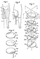
- Fig. 1 is a schematic front elevation of a thigh amputee.
- Fig. 2 is an elevation similar to FIG. 1 schematically illustrating the alignment device of the invention.
- Fig. 3 is an exploded perspective of the device of the invention according to a first embodiment.
- Fig. 4 is an exploded perspective of the device of the invention according to a second embodiment.
- Fig. 5 is a front elevation, on a larger scale, showing the device and according to a preferred embodiment.
- Fig 6 is a section along line VI-VI of fig. 5.
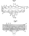
- Fig. 7 is an elevation showing the device in its application to a thigh prosthesis.
- Fig. 8 is a schematic elevation showing the application of the device to a leg prosthesis.
- Fig. 1 shows a right thigh amputee from the front, 1 designating the stump and 2 the femur segment, both the stump and the femur having a deviation from the vertical line shown in 3 as regards the stump and in 3a as regards the healthy leg.
- the invention creates an alignment search device, alignment and orientation generally designated by 4.
- This device is fixed to the lower part of the socket 5 which may be thigh as shown in figs. 2 and 7 or leg as shown in fig. 8 or any other part of the prosthesis.
- the device of the invention is, moreover, connected to a mechanism 6 forming part of the prosthesis 7, this mechanism being able to be a knee or foot joint. as illustrated in figs. 2, 7 and 8 or to another part of the prosthesis.
- Fig. 3 illustrates a first embodiment of the device which has three elements 8, 9 and 10.
- the element 8 has a top 8a intended to be connected to a prosthesis part and a convex bottom 8b.
- the disc 9 has a concave top 9a with the same radius of curvature as the convex underside 8b of the element 8.
- the bottom 9b of the element 9 is planar as is the top 10a of the element 10 whose bottom 10b is intended to be connected for example to the mechanism 6 or to any other prosthesis part.
- the center of the radius of curvature of the convex surface of the element 8 and the concave surface of the element 9 is close to the articular center of the overlying joint C of the prosthesis of the amputee.
- the elements described above with reference to FIG. 3 are advantageously made of a material that is as light as possible and, preferably, of plastic loaded with magnetized material, for example a rubber impregnated with magnetized ferrite.
- This arrangement allows the necessary adjustments to be made, then the elements are locked together for example by means of a pin such as that illustrated in 11 in FIG. 3.
- a rectification of the periphery of the elements displaced relative to each other can also be carried out so that their external generatrices are aligned with those of the socket 5 and of the prosthesis.
- the entire device can then be embedded in resin or surrounded, as well as at least the bottom of the socket and the top of the prosthesis, by adhesive strips to ensure final immobilization.
- Fig. 4 illustrates an alternative embodiment for manufacturing the device in any desired material, for example plastic.
- the device comprises: a first element 12 whose lower face 12a is convex and in which a groove 13 is formed, a second element 14 whose top 14a is concave and has a rib 15 which slides in the groove 13, the underside 14b of the element 14 being itself convex and having a groove 16 which is orthogonal to the rib 15 engaged in the groove 13 of the element 12.
- a third element 17 has, like the element 14, a concave top 17a and a rib 18 corresponding to the groove 16 of the element 14.
- the bottom of the element 17 is plane and has a groove 19 orthogonal to the rib 18.
- a fourth element 20 including the tops and bottoms 20a, 20b are planes present on its top a rib 21 which corresponds to the groove 19 of the element 17 and on its underside a groove 22 to cooperate with a rib 23 formed in a fifth element 24 whose top is plane.
- the displacement of the element 24 relative to the element 20 can be carried out in a plane while the displacement of the element 20 relative to the element 17 can be carried out in a perpendicular plane.
- the ribs and corresponding grooves of these elements being orthogonal, all the plumb adjustments can therefore be made according to the morphology of the amputee to be fitted.
- the relative displacement which can be imparted to the element 17 with respect to the element 14 and to the latter with respect to the element 12 also makes it possible, owing to the relative position of their ribs and grooves, to effect all necessary orientation settings.
- the embodiment described allows manufacture by molding or machining or any other mode permitted by the technique of wooden or plastic parts or any other material and the fixing of the parts together can be ensured by gluing, pinning or any other means. of technique.
- Figs. 5 and 6 illustrate a development of the embodiment of FIG. 4, development according to which the elements 12, 14, 17, 20 and 24 each have grooves 13, ribs 15, grooves 16, ribs 18, etc., which are in the form of a dovetail and which are alternated, so that the successive elements are guided in two perpendicular planes by all of the dovetail assemblies.
- the various elements can be immobilized with respect to each other by means of pins 25, screws or any other suitable means, this until the final adjustment is obtained.
- the top of the first element 8 or 12 is provisionally fixed, for example by gluing, to the base 28 of the socket 5, then the last element 24 on the connection 26 of an element 6, for example by screwing and the adjustments described above are carried out.
- the peripheral edge of the device 4 is machined to adjust the periphery 4a projecting from the base 28 of the socket.
- An embodiment consists in wrapping around the latter ribbons 30 impregnated with plastic material to produce a stratification forming a connection between the socket and the device. Finally, a lining 31 is put in place in a manner known per se to envelop the entire framework of the prosthesis and the device by silhouetting a thigh, a knee and a natural leg.
- the concave or convex surfaces are indifferently spherical or cylindrical generatices.
- Fig. 8 shows an application which is made of the device to a leg prosthesis; in this case the device is mounted immediately above the foot. As previously after adjustment, the periphery of the device is modified to adapt exactly to the external shape which the prosthesis must have.
Landscapes
- Health & Medical Sciences (AREA)
- Cardiology (AREA)
- Oral & Maxillofacial Surgery (AREA)
- Transplantation (AREA)
- Engineering & Computer Science (AREA)
- Biomedical Technology (AREA)
- Heart & Thoracic Surgery (AREA)
- Vascular Medicine (AREA)
- Life Sciences & Earth Sciences (AREA)
- Animal Behavior & Ethology (AREA)
- General Health & Medical Sciences (AREA)
- Public Health (AREA)
- Veterinary Medicine (AREA)
- Prostheses (AREA)
- Analysing Materials By The Use Of Radiation (AREA)
Claims (10)
Priority Applications (1)
| Application Number | Priority Date | Filing Date | Title |
|---|---|---|---|
| AT83400159T ATE35619T1 (de) | 1982-07-30 | 1983-01-24 | Vorrichtung zum finden der ausfluchtung, zum ausfluchten und richten von kunstbeinen. |
Applications Claiming Priority (2)
| Application Number | Priority Date | Filing Date | Title |
|---|---|---|---|
| FR8213332A FR2530945B1 (fr) | 1982-07-30 | 1982-07-30 | Dispositif de recherche d'alignement, d'alignement et d'orientation d'une prothese pour amputation de cuisse ou de jambe |
| FR8213332 | 1982-07-30 |
Publications (2)
| Publication Number | Publication Date |
|---|---|
| EP0102853A1 EP0102853A1 (de) | 1984-03-14 |
| EP0102853B1 true EP0102853B1 (de) | 1988-07-13 |
Family
ID=9276488
Family Applications (1)
| Application Number | Title | Priority Date | Filing Date |
|---|---|---|---|
| EP83400159A Expired EP0102853B1 (de) | 1982-07-30 | 1983-01-24 | Vorrichtung zum Finden der Ausfluchtung, zum Ausfluchten und Richten von Kunstbeinen |
Country Status (5)
| Country | Link |
|---|---|
| US (1) | US4536898A (de) |
| EP (1) | EP0102853B1 (de) |
| AT (1) | ATE35619T1 (de) |
| DE (2) | DE102853T1 (de) |
| FR (1) | FR2530945B1 (de) |
Families Citing this family (45)
| Publication number | Priority date | Publication date | Assignee | Title |
|---|---|---|---|---|
| EP0135319A3 (de) * | 1983-08-24 | 1985-07-24 | ARTHROPLASTY RESEARCH & DEVELOPMENT (PTY) LTD. | Kniegelenkprothese |
| GB2156678B (en) * | 1984-04-04 | 1987-06-10 | Univ London | Proshetic alignment device |
| US5181932A (en) | 1989-04-13 | 1993-01-26 | Phillips L Van | Foot prosthesis having auxiliary ankle construction |
| GB8528992D0 (en) * | 1985-11-25 | 1986-01-02 | Hanger & Co Ltd J E | Alignment device |
| SE454046B (sv) * | 1986-05-12 | 1988-03-28 | Gustav Rennerfelt | Underbensprotes som medger grundinstellning med pasatt protes |
| US4676800A (en) * | 1986-06-02 | 1987-06-30 | Chen Sen J | Adjustable device for artificial limbs |
| GB8627952D0 (en) * | 1986-11-21 | 1986-12-31 | Hanger & Co Ltd J E | Shift device |
| EP0390883B1 (de) * | 1988-09-09 | 1994-12-07 | DRAENERT, Klaus, Dr.med. | Hüftgelenksprothese und ihre verwendung |
| US5658352A (en) * | 1988-09-09 | 1997-08-19 | Draenert; Klaus | Hip prosthesis and its use |
| US4969911A (en) * | 1989-02-17 | 1990-11-13 | United States Manufacturing Company | Adjustable prosthetic joint with alignment means |
| US5290319A (en) | 1991-02-28 | 1994-03-01 | Phillips L Van | Prosthetic foot incorporating adjustable bladders |
| US5514186A (en) * | 1989-04-13 | 1996-05-07 | Phillips; Van L. | Attachment construction for prosthesis |
| US5549714A (en) * | 1990-09-21 | 1996-08-27 | Phillips; Van L. | Symes foot prosthesis |
| FR2671968A1 (fr) * | 1991-01-28 | 1992-07-31 | Proteval | Dispositif de liaison ajustable pour prothese de membre. |
| US5181933A (en) * | 1991-02-28 | 1993-01-26 | Phillips L Van | Split foot prosthesis |
| DE69218230T2 (de) * | 1991-09-30 | 1997-08-21 | Van Lehn Rancho Santa Fe Calif. Phillips | Energiespeichernde pylone einer fussprothese |
| US5458657A (en) * | 1991-12-19 | 1995-10-17 | Becker Orthopedic Appliance Company | Endoskeletal prosthesis having adjustable coupling |
| WO1993017640A1 (en) * | 1992-03-11 | 1993-09-16 | Phillips L Van | Alignment fixture for prosthetic device |
| US5443528A (en) * | 1992-11-17 | 1995-08-22 | Allen; Scott | Coil spring prosthetic foot |
| US5549710A (en) * | 1993-02-03 | 1996-08-27 | Etablissements Proteor | System for assembling two components of a prosthesis in a plurality of adjustable positions |
| FR2700948B1 (fr) * | 1993-02-03 | 1995-03-17 | Proteor Sa | Dispositif modulaire de laison, réglable en position, entre deux constituants d'une prothèse. |
| FR2708194B1 (fr) * | 1993-07-28 | 1995-09-08 | Proteor Sa | Système d'assemblage, en une pluralité de positions réglables en translation de deux constituants d'une prothèse. |
| DE9408556U1 (de) * | 1994-05-25 | 1994-07-21 | Biedermann Motech GmbH, 78054 Villingen-Schwenningen | Testprothese |
| AU5488796A (en) * | 1994-11-29 | 1996-06-19 | Chris L Johnson | Prosthetic joint connector assembly |
| GB2298795A (en) * | 1995-03-10 | 1996-09-18 | Byrne Michael O | Apparatus for aligning a prosthesis |
| DE19529055A1 (de) * | 1995-07-29 | 1997-01-30 | Weihermueller & Voigtmann | Adapter für Prothesen |
| US20020087216A1 (en) * | 1996-02-16 | 2002-07-04 | Atkinson Stewart L. | Prosthetic walking system |
| WO1998040038A1 (en) * | 1997-03-13 | 1998-09-17 | Prosthetic Design, Inc. | Adjustable pyramidal link plate assembly for a prosthetic limb |
| AU2447799A (en) * | 1997-09-08 | 1999-05-03 | Prosthetic Design, Inc. | Prosthetic foot with lateral and angular adjustability |
| US6458163B1 (en) | 2000-07-11 | 2002-10-01 | Prosthetic Design, Inc. | Coupling-socket adapter assembly for a prosthetic limb |
| US20070162140A1 (en) * | 2001-02-27 | 2007-07-12 | Mcdevitt Dennis M | Method and apparatus for reconstructing a joint |
| US6736852B2 (en) * | 2001-02-27 | 2004-05-18 | Incumed, Inc. | Adjustable bone prostheses and related methods |
| GB2411841B (en) * | 2004-03-12 | 2006-08-09 | Univ London | Prosthetic limb attachment |
| US20090082869A1 (en) * | 2007-09-14 | 2009-03-26 | Slemker Tracy C | Double ended pyramid adapter |
| EP2209443A4 (de) * | 2007-09-17 | 2012-08-29 | Linares Medical Devices Llc | Künstliche gelenkstütze zwischen ersten und zweiten knochen |
| US9615944B2 (en) | 2007-10-23 | 2017-04-11 | Rocky Mountain Manufacturing, Llc. | Couplable prosthetic device |
| US7817004B2 (en) * | 2008-05-20 | 2010-10-19 | Cedar Ridge Research, Llc. | Correlated magnetic prosthetic device and method for using the correlated magnetic prosthetic device |
| US8206459B1 (en) | 2009-03-18 | 2012-06-26 | Rehabilitation Institute Of Chicago | Prosthetic-to-liner attachment mechanism |
| US8623092B2 (en) * | 2009-10-10 | 2014-01-07 | Simplicity Orthopedics, Inc. | Method and apparatus for restoring a joint, including the provision and use of a longitudinally-adjustable and rotationally-adjustable joint prosthesis |
| US20120004733A1 (en) * | 2010-06-30 | 2012-01-05 | Hodorek Brian C | Modular articulating prostheses and associated methods |
| DE102011117802B4 (de) | 2011-11-03 | 2016-07-07 | Otto Bock Healthcare Gmbh | Schaftsystem für eine Prothese, Prothese und Herstellungsverfahren |
| DE102012013481B4 (de) | 2012-07-09 | 2019-05-02 | Ottobock Se & Co. Kgaa | Vorrichtung zum Ausrichten eines Prothesenkniegelenkes |
| US20150012113A1 (en) * | 2013-07-03 | 2015-01-08 | Medex International, Inc. | Apparatus for coupling prosthetic components having angular and translational offset |
| US9744056B2 (en) | 2014-08-06 | 2017-08-29 | Rehabilitation Institute Of Chicago | Magnetic electrical connector for assistive devices |
| DE102023107883A1 (de) * | 2023-03-28 | 2024-10-02 | Horus Prosthetics GmbH | Prothesenschaft und verfahren zur herstellung eines prothesenschafts |
Family Cites Families (6)
| Publication number | Priority date | Publication date | Assignee | Title |
|---|---|---|---|---|
| FR965474A (de) * | 1950-09-13 | |||
| US2877506A (en) * | 1953-08-10 | 1959-03-17 | Hans A Almoslino | Transformable rigid structural unit for a body or article supporting assemblage |
| GB1114312A (en) * | 1964-07-24 | 1968-05-22 | Vessa Ltd | Alignment devices for use with limb prostheses |
| US3422462A (en) * | 1966-09-07 | 1969-01-21 | Alan R Finnieston | Prosthetic leg having adjustable alignment means |
| US3538516A (en) * | 1966-10-20 | 1970-11-10 | Rubery Owen & Co Ltd | Adjustable artificial leg for temporary use |
| DE1566404C3 (de) * | 1967-12-27 | 1974-07-11 | Fa. Wilhelm Julius Teufel, 7000 Stuttgart | Justierelement zum Einbau in ein Kunstbein |
-
1982
- 1982-07-30 FR FR8213332A patent/FR2530945B1/fr not_active Expired
-
1983
- 1983-01-24 DE DE198383400159T patent/DE102853T1/de active Pending
- 1983-01-24 EP EP83400159A patent/EP0102853B1/de not_active Expired
- 1983-01-24 AT AT83400159T patent/ATE35619T1/de not_active IP Right Cessation
- 1983-01-24 DE DE8383400159T patent/DE3377330D1/de not_active Expired
- 1983-03-07 US US06/473,134 patent/US4536898A/en not_active Expired - Lifetime
Also Published As
| Publication number | Publication date |
|---|---|
| DE3377330D1 (en) | 1988-08-18 |
| FR2530945A1 (fr) | 1984-02-03 |
| US4536898A (en) | 1985-08-27 |
| FR2530945B1 (fr) | 1986-04-18 |
| DE102853T1 (de) | 1984-08-30 |
| ATE35619T1 (de) | 1988-07-15 |
| EP0102853A1 (de) | 1984-03-14 |
Similar Documents
| Publication | Publication Date | Title |
|---|---|---|
| EP0102853B1 (de) | Vorrichtung zum Finden der Ausfluchtung, zum Ausfluchten und Richten von Kunstbeinen | |
| US4314398A (en) | Method of making a lower leg prostheses | |
| EP0685210B1 (de) | Femorales kondiläres und patellares Implantat, und chirurgisches Instrument für die Implantierung | |
| CA2589641C (fr) | Moule pour la soudure aluminothermique de rails de chemin de fer dont l'un, au moins est use | |
| FR2719466A1 (fr) | Prothèse du genou à ménisque mobile. | |
| FR2846550A1 (fr) | Prothese de disque intervertebral | |
| ATE137950T1 (de) | Kniegelenkprothese | |
| GB2087727A (en) | Manufacture of a prosthetics socket | |
| CA2354167A1 (fr) | Prothese de disque intervertebral a comportement mecanique ameliore | |
| FR2578415A1 (fr) | Lentille intra-oculaire articulee | |
| EP0051022A1 (de) | Brillenscharnier | |
| WO1996020656A1 (fr) | Prothese de genou a glissement | |
| EP0461019B1 (de) | Kugelgelenk für Prothese | |
| EP3595593B1 (de) | Fussprothese mit einem dämpfungselement | |
| CH632663A5 (fr) | Prothese pour articulation bicondylienne. | |
| FR2568467A1 (fr) | Prothese d'articulation du genou. | |
| FR2700260A1 (fr) | Pièce rotulienne artificielle pour prothèse de genou. | |
| FR2698121A1 (fr) | Système d'articulation entre deux éléments rigides, par exemple entre une branche et une face de monture de lunettes, et procédé d'articulation correspondant. | |
| FR2835178A1 (fr) | Ensemble prothetique tibial pour prothese du genou a glissement | |
| WO1996000538A1 (fr) | Articulation prothetique du genou, notamment prothese unicompartimentale du genou, ou prothese de la rotule | |
| WO1998020818A1 (fr) | Prothese totale du genou | |
| FR2679765A1 (fr) | Fixateur externe axial. | |
| FR2700263A1 (fr) | Prothèse d'articulation du genou. | |
| US4178642A (en) | Knee joint structure for artificial legs | |
| FR2648880A1 (fr) | Ensemble d'entrainement pour joint universel |
Legal Events
| Date | Code | Title | Description |
|---|---|---|---|
| PUAI | Public reference made under article 153(3) epc to a published international application that has entered the european phase |
Free format text: ORIGINAL CODE: 0009012 |
|
| 17P | Request for examination filed |
Effective date: 19830125 |
|
| AK | Designated contracting states |
Designated state(s): AT BE CH DE GB IT LI LU NL SE |
|
| ITCL | It: translation for ep claims filed |
Representative=s name: STUDIO KOHLER FONTANA |
|
| TCAT | At: translation of patent claims filed | ||
| TCNL | Nl: translation of patent claims filed | ||
| DET | De: translation of patent claims | ||
| GRAA | (expected) grant |
Free format text: ORIGINAL CODE: 0009210 |
|
| AK | Designated contracting states |
Kind code of ref document: B1 Designated state(s): AT BE CH DE GB IT LI LU NL SE |
|
| PG25 | Lapsed in a contracting state [announced via postgrant information from national office to epo] |
Ref country code: SE Effective date: 19880713 Ref country code: NL Effective date: 19880713 Ref country code: IT Free format text: LAPSE BECAUSE OF FAILURE TO SUBMIT A TRANSLATION OF THE DESCRIPTION OR TO PAY THE FEE WITHIN THE PRESCRIBED TIME-LIMIT;WARNING: LAPSES OF ITALIAN PATENTS WITH EFFECTIVE DATE BEFORE 2007 MAY HAVE OCCURRED AT ANY TIME BEFORE 2007. THE CORRECT EFFECTIVE DATE MAY BE DIFFERENT FROM THE ONE RECORDED. Effective date: 19880713 |
|
| REF | Corresponds to: |
Ref document number: 35619 Country of ref document: AT Date of ref document: 19880715 Kind code of ref document: T |
|
| REF | Corresponds to: |
Ref document number: 3377330 Country of ref document: DE Date of ref document: 19880818 |
|
| GBT | Gb: translation of ep patent filed (gb section 77(6)(a)/1977) | ||
| NLV1 | Nl: lapsed or annulled due to failure to fulfill the requirements of art. 29p and 29m of the patents act | ||
| PG25 | Lapsed in a contracting state [announced via postgrant information from national office to epo] |
Ref country code: AT Effective date: 19890124 |
|
| PG25 | Lapsed in a contracting state [announced via postgrant information from national office to epo] |
Ref country code: LU Free format text: LAPSE BECAUSE OF NON-PAYMENT OF DUE FEES Effective date: 19890131 Ref country code: LI Effective date: 19890131 Ref country code: CH Effective date: 19890131 Ref country code: BE Effective date: 19890131 |
|
| PLBE | No opposition filed within time limit |
Free format text: ORIGINAL CODE: 0009261 |
|
| STAA | Information on the status of an ep patent application or granted ep patent |
Free format text: STATUS: NO OPPOSITION FILED WITHIN TIME LIMIT |
|
| 26N | No opposition filed | ||
| BERE | Be: lapsed |
Owner name: ETS PROTEOR Effective date: 19890131 |
|
| REG | Reference to a national code |
Ref country code: CH Ref legal event code: PL |
|
| REG | Reference to a national code |
Ref country code: GB Ref legal event code: IF02 |
|
| PGFP | Annual fee paid to national office [announced via postgrant information from national office to epo] |
Ref country code: GB Payment date: 20020123 Year of fee payment: 20 |
|
| PGFP | Annual fee paid to national office [announced via postgrant information from national office to epo] |
Ref country code: DE Payment date: 20020227 Year of fee payment: 20 |
|
| PG25 | Lapsed in a contracting state [announced via postgrant information from national office to epo] |
Ref country code: GB Free format text: LAPSE BECAUSE OF EXPIRATION OF PROTECTION Effective date: 20030123 |
|
| REG | Reference to a national code |
Ref country code: GB Ref legal event code: PE20 Effective date: 20030123 |