EP0102841A1 - Rayonnage - Google Patents
Rayonnage Download PDFInfo
- Publication number
- EP0102841A1 EP0102841A1 EP83305105A EP83305105A EP0102841A1 EP 0102841 A1 EP0102841 A1 EP 0102841A1 EP 83305105 A EP83305105 A EP 83305105A EP 83305105 A EP83305105 A EP 83305105A EP 0102841 A1 EP0102841 A1 EP 0102841A1
- Authority
- EP
- European Patent Office
- Prior art keywords
- members
- upright
- transverse
- shelf
- connectors
- Prior art date
- Legal status (The legal status is an assumption and is not a legal conclusion. Google has not performed a legal analysis and makes no representation as to the accuracy of the status listed.)
- Withdrawn
Links
- NJPPVKZQTLUDBO-UHFFFAOYSA-N novaluron Chemical compound C1=C(Cl)C(OC(F)(F)C(OC(F)(F)F)F)=CC=C1NC(=O)NC(=O)C1=C(F)C=CC=C1F NJPPVKZQTLUDBO-UHFFFAOYSA-N 0.000 claims abstract description 18
- 230000000153 supplemental effect Effects 0.000 claims abstract description 13
- 238000010276 construction Methods 0.000 description 11
- 238000004519 manufacturing process Methods 0.000 description 4
- 239000002184 metal Substances 0.000 description 4
- 238000005096 rolling process Methods 0.000 description 4
- 230000004048 modification Effects 0.000 description 3
- 238000012986 modification Methods 0.000 description 3
- 230000000694 effects Effects 0.000 description 2
- 238000003860 storage Methods 0.000 description 2
- 230000000712 assembly Effects 0.000 description 1
- 238000000429 assembly Methods 0.000 description 1
- 230000008878 coupling Effects 0.000 description 1
- 238000010168 coupling process Methods 0.000 description 1
- 238000005859 coupling reaction Methods 0.000 description 1
- 238000009408 flooring Methods 0.000 description 1
- 238000005304 joining Methods 0.000 description 1
- 239000000463 material Substances 0.000 description 1
- 238000004080 punching Methods 0.000 description 1
- 230000003014 reinforcing effect Effects 0.000 description 1
- 230000000717 retained effect Effects 0.000 description 1
- 238000000926 separation method Methods 0.000 description 1
Images


Classifications
-
- A—HUMAN NECESSITIES
- A47—FURNITURE; DOMESTIC ARTICLES OR APPLIANCES; COFFEE MILLS; SPICE MILLS; SUCTION CLEANERS IN GENERAL
- A47B—TABLES; DESKS; OFFICE FURNITURE; CABINETS; DRAWERS; GENERAL DETAILS OF FURNITURE
- A47B57/00—Cabinets, racks or shelf units, characterised by features for adjusting shelves or partitions
- A47B57/06—Cabinets, racks or shelf units, characterised by features for adjusting shelves or partitions with means for adjusting the height of the shelves
- A47B57/20—Cabinets, racks or shelf units, characterised by features for adjusting shelves or partitions with means for adjusting the height of the shelves consisting of tongues, pins or similar projecting means coacting with openings
- A47B57/22—Cabinets, racks or shelf units, characterised by features for adjusting shelves or partitions with means for adjusting the height of the shelves consisting of tongues, pins or similar projecting means coacting with openings characterised by shape or orientation of opening, e.g. keyhole-shaped
-
- F—MECHANICAL ENGINEERING; LIGHTING; HEATING; WEAPONS; BLASTING
- F16—ENGINEERING ELEMENTS AND UNITS; GENERAL MEASURES FOR PRODUCING AND MAINTAINING EFFECTIVE FUNCTIONING OF MACHINES OR INSTALLATIONS; THERMAL INSULATION IN GENERAL
- F16B—DEVICES FOR FASTENING OR SECURING CONSTRUCTIONAL ELEMENTS OR MACHINE PARTS TOGETHER, e.g. NAILS, BOLTS, CIRCLIPS, CLAMPS, CLIPS OR WEDGES; JOINTS OR JOINTING
- F16B2200/00—Constructional details of connections not covered for in other groups of this subclass
- F16B2200/20—Connections with hook-like parts gripping behind a blind side of an element to be connected
-
- F—MECHANICAL ENGINEERING; LIGHTING; HEATING; WEAPONS; BLASTING
- F16—ENGINEERING ELEMENTS AND UNITS; GENERAL MEASURES FOR PRODUCING AND MAINTAINING EFFECTIVE FUNCTIONING OF MACHINES OR INSTALLATIONS; THERMAL INSULATION IN GENERAL
- F16B—DEVICES FOR FASTENING OR SECURING CONSTRUCTIONAL ELEMENTS OR MACHINE PARTS TOGETHER, e.g. NAILS, BOLTS, CIRCLIPS, CLAMPS, CLIPS OR WEDGES; JOINTS OR JOINTING
- F16B2200/00—Constructional details of connections not covered for in other groups of this subclass
- F16B2200/30—Dovetail-like connections
-
- Y—GENERAL TAGGING OF NEW TECHNOLOGICAL DEVELOPMENTS; GENERAL TAGGING OF CROSS-SECTIONAL TECHNOLOGIES SPANNING OVER SEVERAL SECTIONS OF THE IPC; TECHNICAL SUBJECTS COVERED BY FORMER USPC CROSS-REFERENCE ART COLLECTIONS [XRACs] AND DIGESTS
- Y10—TECHNICAL SUBJECTS COVERED BY FORMER USPC
- Y10T—TECHNICAL SUBJECTS COVERED BY FORMER US CLASSIFICATION
- Y10T403/00—Joints and connections
- Y10T403/71—Rod side to plate or side
- Y10T403/7117—Flanged or grooved rod
Definitions
- the present invention relates generally to storage shelves and in particular to an adjustable, an easily assembled, and self supporting shelf system.
- a variety of metal shelving units and/or storage racks are available today or have been suggested by .the prior art. These units usually comprise at least four vertical members and a plurality of shelves that are attached to and extend between the vertical members. Alternately, some units use horizontal elements to tie the uprights together which in turn support shelves or ' other components. In the past, in many if not most of these devices, the horizontal and vertical members would be secuted together by one or more threaded fasteners.
- the vertical members include a series of longitudinally spaced apertures and the shelves include companion apertures formed in the corners which are aligned with the apertures in the vertical members. A threaded fastener extends through the aligned apertures to lock the shelves to the vertical support member. With this type of arrangement, assembly of the unit would usually be laborious and time comsuming.
- Shelving arrangements have also been suggested which reduce the need for separate threaded fasteners.
- Some of these prior proposals included the use of rivets secured to the shelf which would extend through suitably formed apertures in the vertical support members.
- the shelf unit would include a tab formed near the corner which would be engaged with an opening in the upright member.
- this latter proposal would also provide apertures in both the shelf and upright for receiving a threaded fastener to positively secure the shelf to the upright.
- overall shelf stability would be achieved with separate bracing members that would extend diagonally across the sides and/or rear of the shelf unit. This cross bracing adds to the manufacturing cost and increases the overall assembly time for the shelf.
- adjustment and/or removal of a shelf or transverse element would take considerable effort.
- the present invention provides a new and improved shelf system in which vertical and transverse members are securely interlocked to each other and in which supplemental cross bracing is not required to provide the necessary shelf rigidity.
- the shelf assembly comprises vertical, load supporting upright members and transverse beam members interlocked to provide a self supporting, rigid structure.
- the rigid interlocking between an upright member and a beam member is achieved by connectors formed on one of the members which engage and interlock with apertures formed in the other member.
- the connectors form part of the transverse beam members whereas the apertures form part of the upright members.
- each connector comprises an upright engaging lug spaced from the face of the beam by a keyed pedestal.
- the keyed pedestal is defined by an elongate projection having spaced end portions or lug support legs joined on one side by a curved interconnecting wall portion:
- the upright engaging lug extends laterally from the top of the projection to define a track between the lug and the face of the transverse beam between which a portion of the upright adjacent the aperture, is captured.
- Each upright includes at least one pair of apertures, sized to receive and interlock with the connectors formed on the end of a beam.
- a plurality of aperture pairs are spaced longitudinally along the upright so that multiple beam members can be engaged with the upright at various locations.
- Each aperture is defined by a substantially vertical, elongate slot having upper and lower slot segment.
- a clearance notch extends laterally from one side of the upper slot segment.
- the upper slot segment and clearance notch are sized to readily receive a connector, specifically allowing the lug to pass through the upright.
- the lower slot segment preferably is sized to create an interference fit with the keyed pedestal. The interference fit is preferably achieved by gradually narrowing the transverse dimension of the lower slot segment.
- a beam is releaseably interlocked to an upright by inserting the connector pair through the upper slot segments of the desired aperture pair and then displacing the beam downwardly with respect to the upright so that the sides of the keyed pedestal engage the edges of the lower slot segment.
- the lugs overlie face portions of the upright adjacent one side of the lower slot segments to prevent the beam and upright from separating.
- the keyed pedestal not only provides a support for the upright engaging lug, it also coacts with the edges of the slot to prevent relative rotation between the upright and interlocked beam.
- holes are preferably formed in the beams above the connectors which become aligned with the upper slot segments when the beam is moved to the interlocked position.
- a fastener or clip can be placed in the aligned openings to secure the interlocking between the members.
- each lug support leg of the projection wall defines an area of contact with one side edge of the lower slot segment.
- the curved interconnecting wall forms a contact area with the other side edge of the slot segment.
- three spaced areas of contact between the pedestal and the slot segment are defined.
- the areas defined on the support legs and the area defined on the curved interconnecting wall are positioned on either side of an imaginary center line drawn through the vertical center of each pedestal.
- the disclosed engagement provides a self supporting shelf assembly that does not require additional cross bracing to provide structural rigidity.
- the con- nector/aperture engagement between the vertical and transverse members inhibits both lateral and rotative movement between the members.
- the projection/aperture engagement provides a rather rigid connection, the two members can still be easily disassembled for adjustment, shelf modification, shelf repositioning, etc.
- each planar section of each upright includes a plurality of paired apertures, spaced longitudinally along the longitudinal extent of the uprights.
- the projections formed on opposite ends of each transverse beam are preferably integrally formed with the beam end by a suitable punching or drawing operation.
- the projec- . tions are merely struck near the ends of each beam as a step in the overall beam construction.
- the beam configuration lends itself to automated production methods and machines, reducing labor expense, while still providing a strong, easily assembled shelf unit that eliminates the need for separate fasteners or locking structure, attached to one or more members in a separate manufacturing operation.
- a “T” upright is also disclosed which provides a means for readily interlocking adjacent shelf units.
- the "T” upright comprises a pair of coplanar flat sections joined by a "U”-shaped extension oriented at 90° to the flat sections.
- the flat sections and extension- each include a plurality of apertures engageable with transverse members of one or more shelf units.
- Supplemental support members are disclosed which can be easily engaged with oposite transverse beams to provide added support for shelves and components, and which can also serve as rack dividers.
- a tie bar is disclosed which is used in connection with the "T" upright to interlock adjacent, but spaced apart shelf units.
- the tie bar can serve as a foundation for a raised aisleway in a multi-story shelf assembly.
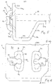
- FIG. 1 illustrates the overall view of a shelf assembly 10 embodying the present invention.
- the shelf assembly comprises four corner uprights 12, and a plurality of transverse beam members, indicated generally by the reference character 14 that extend between and interlock with adjacent corner uprights.
- the longer transverse beam members ex-.- tending across the front and back of the shelf unit 10 are designated by the reference character 14a, whereas the shorter transverse members extending front to back are designated by the reference character 14b.
- the interlocking members between the uprights 12 and the transverse members 14a, 14b are substantially identical.
- each transverse beam is longitudinally uniform and comprises a substantially flat side panel 30 and an integrally formed, rigidizing flange 32.
- the flange 32 includes a lateral extension 32a that joins the side panel 30, a support lip 32b.that extends substantially parallel with the lateral extension 32a and an angled portion 32c that joins the support lip 32b, to the extension 32a.
- the lip 32b defines a support for a shelf 34 (indicated in phantom in Figure 5) or other component.
- transverse members 14 (2 pairs of members 14a, 14b) mounted at the same level on the uprights 12 define a shelf support.
- the shelf is sized to fit within the perimeter defined by the transverse members and thus movement in the shelf is restricted by inside surfaces 30a of the side panels 30.
- the connectors 20 are preferably formed near the ends of each transverse beam.
- the connectors 20 each comprise a lug 40 spaced from an outside face 30b of the side panel 30 by a keyed pedestal 42.
- the pedestal 42 is formed by an elongate projection defined by spaced, upper and lower lug supporting-legs 44, 46, joined on one side by a curved interconnecting wall 48.
- the lug 40 extends laterally from the pedestal in a direction substantially parallel with the plane of the outer face 30b of the side panel 30. With this arrangement, a track 49 is defined between the surface 30b and an undersurface 40a of the lug 40 for receiving a portion of the upright 12.
- the lugs 40 and keyed pedestals 42 are preferably struck from the face panel 30 of the transverse beam 14, in one or more metal forming steps.
- the connectors 20 are integrally formed with the beam members and the entire construction of the beam can thus be accomplished on high speed automatic metal forming equipment such as roll formers.
- the apertures 22 are constructed to easily receive and interlock with a pair of connectors 20 formed at the ends of a transverse beam.
- Each aperture 22 comprises an elongate slot having upper and lower slot segments 50a, 50b.
- a lug clearing notch 52 extends laterally from one side of each upper slot portion 50a.
- the transverse dimension of the lower slot segment 50b gradually narrows from top to bottom so that an interference fit is created when the connectors 20 are engaged.
- the connectors 20 formed at the end of the transverse beam 14 are interlocked with a pair of apertures 22 formed in an upright 12 by first positioning the upright 12 and the beam 14 as shown in Figure 2 so that the connectors 20 pass through the upper slot segments 50a of the apertures 22.
- the transverse beam 14 is then moved downwardly (as viewed in Figure 2) so that the connectors - 20 move into the position shown in Figure 3.
- a portion of the upright indicated by the reference character 60 in Figure 2 is captured between the undersurface of the lug 40 and the outside face 30b of the transverse beam. This lug/upright engagement, prevents the beam and upright from lateral separation.
- the lug pedestals 42 are keyed to provide an interference fit with the lower slot segments 50b when the connectors 20 are bottomed (as shown in Figure 3).
- the interference engagement between the pedestals and lower slot segments inhibits relative rotational movement between the uprights 12 and the transverse beam 14, thus providing an extremely rigid interlocking of the shelf members, eliminating the need for supplementary cross-bracing.
- the connectors 20 when the connectors 20 are fully seated in the lower slot segments 50b, at least three areas of contact between the pedestal 42 and the lower slot segment 50b occur.
- these areas of engagement are indicated by the reference characters 62a, 62b and 62c.
- the contact areas 62a, 62b are preferably effected between the lug-side of the lug support legs 44, 46 and one edge of the lower slot segment 50b.
- the contact 62c is effected between the interconnecting wall 48 and the opposite edge of the lower slot segment 50b.
- this arrangement provides three spaced areas of contact with the areas 62a, 62b, and the area 62c disposed in either side of an imaginary vertical centerline 64 drawn through the connector.
- the engagement between the keyed pedestal 42 and the aperture 22 resists relative rotation between an upright and a transverse beam, thus creating a rather rigid interlocking.
- the contact areas 62a and 62c define lines of contact between the edges of the lower slot segment 50b and the support leg 46 and the interconnecting wall 48, respectively. Consequently, a wedging engagement between the keyed pedestal 42 and the edges of the lower slot segment 50b is achieved when the connectors 20 are in the interlocked position shown in Figure 3.
- each lug 40 includes a reinforcing rib 66 to add additional rigidity to the lug.
- the rib imparts a slight radius to the lug 40, as seen in Figure 5.
- the radius not only strengthens the lug 40 but the curved undersurface 40a facilitates the engagement between a transverse member 14 and the upright 12.
- the curved undersurface 40a provides a "lead" so that when the connectors are moved from the position shown in Figure 2 to the position in Figure 3, the rounded edge defined by the lower surface 40a of the lug 40 easily overlaps the outer face 30b of the upright to facilitate the movement of the beam 14 into its final interlocked position.
- the transverse beam may be formed with holes 70 located a spaced distance above the connectors 20 as seen in Figure 2.
- holes 70 are aligned with respective upper slot segments 50a.
- a bolt or safety clip (not shown) can be inserted through the aligned opening to provide a rather permanent connection of the upright 12 and beam 14, if desired.
- each corner upright 12 comprises two adjacent flat sections 12a, 12b oriented at an angle of substantially 90° with respect to each other to define an L-shaped configuration.
- a plurality of pairs of the apertures 22 are spaced longitudinally along the entire length of each flat section 12a, 12b, enabling a plurality of transverse members 14a, 14b to be engaged at various locations to define plural shelf locations.
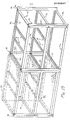
- Figures 1.0-12 illustrate the construction of a "T" upright 80 for joining adjacent shelf units which also embodies the present invention.
- Figure 13 illustrates two interconnected shelf units utilizing the "T" uprights 80.
- the "T" upright comprises two spaced, co-planar, flat sections 80a joined together by a U-shaped extension 80b that comprises a pair of substantially parallel flat wall extensions 82, 84 interconnected by an arcuate wall 86.
- the wall extensions 82, 84 join the flat sections 80a at an angle of substantially 90°.
- Aligned pairs of apertures 22 are disposed longitudinally along the flat sections 80a and the wall extensions 82, 84.
- At least two of the corner uprights 12 are replaced with " T " uprights 80 as shown in Figure 13.
- the front and back transverse members 14a of the adjacent shelf units interlock with the flat sections 80a whereas the front-to-back transverse beams 14b interlock with at least one of the wall extensions 82, 84.
- a single front-to-back transverse beam 14b extending between the U-shaped extensions 80b of the " T " uprights 80 will be sufficient at each shelf location. If added strength is desired, transverse beams 14b can be interlocked with both wall extensions 82, 84 as shown in Figure 13.
- the transverse beams 14a, 14b are positioned with their flanges 32 on top, that is, inverted from the position shown in Figures 2-5.
- the shelves 34 sit atop the flange extensions 32a (shown in the inverted position in Figure 5) of the flanges 32 and are retained in position by the uprights.
- the shelving assembly shown in Figure 13 includes supplemental support members 88 that extend front-to-back, that is, parallel to the transverse beams 14b.
- the supports 88 engage and are supported by the transverse beams 14a.
- the supplemental supports 88 provide additional support for the shelves 34 and in addition can serve as dividers, as well as component and hanger supports for shelf applications such as racks for storing and supporting automobile/truck exhaust pipe inventories.
- the supplemental supports 88 comprise elongate members having a channel-like construction.
- Each member 88 includes a flat planar section 88a which abuttably engages the underside of a shelf 34 when the member 88 is used as a shelf support.
- a pair of rigidizing flanges 88b depend downwardly from either side of the flat section 88a.
- Each flange 88b includes leg portions 90, 91 joined by a short transverse web 92. The size of the legs 91, 92 can be varied to suit particular strength requirements.
- the flat section 88a and flanges 88b include apertures 93 for receiving fasteners, hangers, etc.
- a tab 94 depends downwardly at each end of the supplemental member 88 and preferably includes a small aperture 94a.
- the tabs 94 are engaged with slots 96 in opposite transverse members 14a formed at spaced locations in the flange 32 near the juncture of the flange extension 32a and the connecting web 32c. It should thus be appreciated that the supplemental members 88 are easily installed in a shelf unit, by merely inserting the tabs 94 into the slots 96 in opposite transverse beams. To maintain the engagement, the tabs 94 can be bent or alternately, fasteners such as screws or clips (not shown) can be placed in the tab apertures 94a.
- the disclosed "T" upright 80 provides yet another feature of the present invention.
- the spaced apart shelf units can only be joined with the use of special brackets or other components that are fastened to the respective shelf units by separate fasteners.
- spaced apart shelf units are connected using a tie bar 96 illustrated in Figure 17 which includes connectors 20, substantially identical to those forming part of the transverse beams, which interlock with the apertures 22 in the "T" section.
- the tie bar 96 (which is shown standing on end in Figure 17) includes a flat planar section 96a and a pair of 90° flanges 90b which serve to reinforce the tie bar.
- tie bars 96 can serve not only as a means for "tying together" space shelf units but can serve as a support for a raised aisleway in multiple story shelf assemblies.
- the corner and "T" uprights 12, 80 can be manufactured in lengths of 10 feet or longer to provide shelf units more than 15 feet tall (2 stories).
- tie bars 96 can be used to interconnect two spaced shelf units which in turn serve as a support for grating or flooring to define an aisleway space above ground level between the adjacent shelf units.
- each flat section 80a is interlocked with a transverse beam 14a.
- At least one leg of the U section is interlocked with a front-to-back transverse beam 14b.
- a tie bar 96 is inserted inside the U-shaped extension and interlocked with one of the extension walls 82, 84 forming the U-shaped extension.
- the transverse beams 14a, 14b would be interlocked with apertures 22 all located at the same level of the "T" upright 80.
- the tie bar 96 would preferably be interlocked with a set of apertures spaced above or below the apertures engaged by the transverse members.
- the transverse member 14 illustrated in the Figures, includes a pair of symmetrical connectors 20 at each end which as indicated previously enables the beam 14 to be installed with the flange 32 either at the top or the bottom. If a stronger transverse member is desired, the side panel 30, or for that matter the flange 32 can be increased in size to provide the additional strength needed. In the preferred embodiment, additional strength in the transverse beam 14 is,obtained by increasing the width of the side panel 30.
- two pairs of connectors 20 can be incorporated to provide a stronger interlocking engagement between an upright and a transverse member. Modifications can also be made to reduce material cost for shelves intended for very light applications.
- the "T" upright 80 illustrated in Figures 10-12 is illustrated with an extension 80b comprising two wall extensions 82, 84, each formed with a plurality of pairs of apertures 22.
- single apertures 22 spaced longitudinally along each wall extension 82, 84 can be utilized which engage transverse members having only a single connector 20, or alternately a vertically spaced pair of connectors 20 (not shown).
- the flanges shown for the various members can be reduced in size or even eliminated for light duty applications.
- Each of the shelf elements is configured to facilitate manufacture on high speed metal forming equipment such as rolling equipment. Consequently, the various members can be manufactured continuously and cut into any length desired so that relatively large shelf units can be assembled.
- the same tooling, with minimum modification or adjustment can roll the shelf members for both light and heavy duty shelf units.
- the same rolling equipment could form transverse members 14 having various side panel widths. In effect, the strength of a transverse member would be determined by the initial width of the sheet stock fed to the rolling equipment. The wider the initial stock, the wider the side panel 30 and hence the stronger the finished transverse member.
- FIGS 20a-d illustrates a range of transverse beams 14 denoted for purposes of explanation as 14', 14", 14''' and 14''''.
- additional strength is obtained by increasing the width of the side panel 30 and the addition of another rigidizing flange 98 (shown in Figure 20d as part of beam 14'''').
- the flange 32 remains unchanged, so that all four illustrated beams can be formed on the same rolling equipment with minimal change.
- the width of the initial stock dictates the strength of the resulting beam.
- additional connectors 20 are formed at the beam ends in the higher strength beams 14"', 14''''.
- the connectors 20 are formed symmetrically so that the beams 14 shown in these two Figures can also be installed in the inverted position.
- shelf units can be quickly assembled without the need for separate fasteners.
- the interlocking provides an extremely rigid structure without the need for separate cross bracing, but yet is easily disassembled if shelf repositioning, removal, etc. is needed.
- the location of the shelves (or transverse member 14) is fully adjustable by virtue of the plurality of apertures 22 formed along the length of the uprights.
Landscapes
- Assembled Shelves (AREA)
Applications Claiming Priority (2)
| Application Number | Priority Date | Filing Date | Title |
|---|---|---|---|
| US414554 | 1982-09-03 | ||
| US06/414,554 US4549665A (en) | 1982-09-03 | 1982-09-03 | Shelf assembly |
Publications (1)
| Publication Number | Publication Date |
|---|---|
| EP0102841A1 true EP0102841A1 (fr) | 1984-03-14 |
Family
ID=23641953
Family Applications (1)
| Application Number | Title | Priority Date | Filing Date |
|---|---|---|---|
| EP83305105A Withdrawn EP0102841A1 (fr) | 1982-09-03 | 1983-09-02 | Rayonnage |
Country Status (2)
| Country | Link |
|---|---|
| US (1) | US4549665A (fr) |
| EP (1) | EP0102841A1 (fr) |
Cited By (2)
| Publication number | Priority date | Publication date | Assignee | Title |
|---|---|---|---|---|
| EP0752223A3 (fr) * | 1995-07-05 | 1997-05-02 | Anemos S P A | Dispositif d'accouplement pour des étagères métalliques de construction légère |
| EP1605217A3 (fr) * | 2004-06-11 | 2014-11-05 | Whirlpool Corporation | Support multifonctionnel pour étagères d'appareils frigorifiques, en particulier approprié aux systèmes d'appareils modulaires |
Families Citing this family (30)
| Publication number | Priority date | Publication date | Assignee | Title |
|---|---|---|---|---|
| US4646656A (en) * | 1985-09-26 | 1987-03-03 | Marschak Howard J | Base shelf locking mechanism |
| US4996929A (en) * | 1989-10-10 | 1991-03-05 | Saal Bruno P | Shelf frame connector |
| US5489162A (en) * | 1993-02-10 | 1996-02-06 | Digital Equipment Corporation | Fastening |
| US5485932A (en) * | 1994-05-03 | 1996-01-23 | Digital Equipment Corporation | Wall mountable modular component mounting system |
| US5495954A (en) * | 1994-05-16 | 1996-03-05 | Schmit; Joel A. | Modular storage unit kit |
| ES1029021Y (es) * | 1994-09-14 | 1996-01-01 | Esmena Sa | Larguero para la formacion de estanterias. |
| CA2174008C (fr) * | 1996-04-12 | 2001-02-20 | Jaime Benayon | Etageres |
| USD430431S (en) * | 1999-02-17 | 2000-09-05 | Fehlbaum & Co. | Display unit |
| US6450350B1 (en) * | 2000-06-12 | 2002-09-17 | John V. R. Krummell, Jr. | Storage rack system with flared end load beam |
| US20030094124A1 (en) * | 2001-11-20 | 2003-05-22 | Wishart Andrew S. | Modular pallet display system |
| GB2388015A (en) * | 2002-05-01 | 2003-11-05 | Jennifer Frances Massicott | Shelf support bracket |
| US7070021B1 (en) | 2003-01-10 | 2006-07-04 | Mckinney Steven L | Rack step tool |
| US20060144809A1 (en) * | 2004-12-30 | 2006-07-06 | Edsal Manufacturing Co., Inc. | Shelving connector |
| US20060196842A1 (en) * | 2005-03-04 | 2006-09-07 | Taylor Harry R | Storage rack |
| US7950533B2 (en) * | 2006-02-03 | 2011-05-31 | Honda Motor Co., Ltd. | Muffler pipe rack and hanger system |
| US7867768B2 (en) * | 2007-02-08 | 2011-01-11 | Ortho-Clinical Diagnostics, Inc. | Two dimensional sample handler |
| US20100089699A1 (en) * | 2008-10-15 | 2010-04-15 | Meltz George R | System and apparatus for supportive scaffolding |
| US8522987B2 (en) * | 2010-05-26 | 2013-09-03 | Seville Classics Inc | Storage rack |
| US9375102B2 (en) * | 2010-07-02 | 2016-06-28 | Edsal Manufacturing Company, Inc. | Portion of shelf and support for shelving unit |
| US8733564B2 (en) * | 2010-07-02 | 2014-05-27 | Edsal Manufacturing Co., Inc. | Variable configuration shelving apparatus and methods |
| CN102340941A (zh) * | 2010-07-16 | 2012-02-01 | 鸿富锦精密工业(深圳)有限公司 | 机柜 |
| CN102762043A (zh) * | 2011-04-27 | 2012-10-31 | 鸿富锦精密工业(深圳)有限公司 | 电子装置壳体 |
| PL2983552T3 (pl) | 2013-04-08 | 2018-06-29 | Présentoirs One Way Inc. | Modułowy system regałowy |
| RU2639618C1 (ru) * | 2016-07-26 | 2017-12-21 | Общество с ограниченной ответственностью "Эргономика Пространства" (ООО "Эргономика Пространства") | Узел крепления элементов стеллажной конструкции |
| US10299594B2 (en) * | 2017-03-28 | 2019-05-28 | Edsal Manufacturing Company, Inc. | Shelving unit with capacity increasing tie members |
| WO2018185752A1 (fr) * | 2017-04-03 | 2018-10-11 | Globerman Eyal | Procédé pour la fabrication d'étagères |
| US11896121B2 (en) | 2017-04-03 | 2024-02-13 | Eyal GLOBERMAN | Method for making shelves |
| DE102017128745A1 (de) * | 2017-12-04 | 2019-06-06 | Grass Gmbh | Führungsschiene eines Führungssystems, Führungssystem, Verfahren zur Herstellung einer Führungsschiene und Möbel |
| USD942784S1 (en) * | 2019-10-08 | 2022-02-08 | Brian Burge | Table |
| CA3192968A1 (fr) * | 2020-09-16 | 2022-03-24 | Jared W. Hanlon | Rayonnage utilitaire |
Citations (4)
| Publication number | Priority date | Publication date | Assignee | Title |
|---|---|---|---|---|
| US3208778A (en) * | 1962-10-04 | 1965-09-28 | Storack Corp | Interlocking structural members |
| DE1803107A1 (de) * | 1968-03-07 | 1969-10-16 | Giacomo Valsesia | Regal aus Metall |
| DE3002401A1 (de) * | 1979-01-26 | 1980-08-07 | Gabriele Pozzer | Im baukastensystem zusammensetzbares regal |
| FR2447164A1 (fr) * | 1979-01-26 | 1980-08-22 | Guillemin Henri | Rayonnage |
Family Cites Families (63)
| Publication number | Priority date | Publication date | Assignee | Title |
|---|---|---|---|---|
| US3273720A (en) * | 1966-09-20 | Storage racks | ||
| NL285256A (fr) * | ||||
| US1254094A (en) * | 1916-10-16 | 1918-01-22 | Engelbert J Vogt | Adjustable bracket. |
| US1288010A (en) * | 1918-07-06 | 1918-12-17 | William Harry Isaac | Shelf-bracket. |
| US2932409A (en) * | 1954-12-09 | 1960-04-12 | Jr Walter G Wineman | Metal shelving |
| US2932368A (en) * | 1956-06-15 | 1960-04-12 | Storage Products Corp | Structural lock |
| US2918176A (en) * | 1957-02-25 | 1959-12-22 | Allen Iron & Steel Company | Storage rack |
| US3045834A (en) * | 1957-07-25 | 1962-07-24 | Edward A Seiz | Rack construction |
| US2990920A (en) * | 1958-01-21 | 1961-07-04 | Republic Steel Corp | Structural building elements |
| US2895619A (en) * | 1958-06-27 | 1959-07-21 | Midland Machine Corp | Storage rack |
| US2948409A (en) * | 1958-07-11 | 1960-08-09 | Equipment Mfg Inc | Rack construction |
| US2984363A (en) * | 1958-07-24 | 1961-05-16 | Mechanical Handling Sys Inc | Adjustable rack |
| US3097747A (en) * | 1959-05-19 | 1963-07-16 | Bernard Gloekler North East Co | Pallet rack |
| US3043409A (en) * | 1959-05-25 | 1962-07-10 | Rapids Standard Co Inc | Perforated structural angle |
| DE1828519U (de) * | 1960-03-03 | 1961-03-23 | Fausto Nember | Aus einzelnen teilen zusammmenzusetzendes regal bzw. gestell. |
| US3070237A (en) * | 1960-06-30 | 1962-12-25 | Acme Steel Co | Pallet rack |
| US3055462A (en) * | 1960-10-21 | 1962-09-25 | Bathey Mfg Company | Self-locking connection for structural members |
| US3106297A (en) * | 1960-11-21 | 1963-10-08 | Acme Steel Co | Pallet rack |
| US3096108A (en) * | 1961-03-16 | 1963-07-02 | Green Penny Co | Adjustable rack connection |
| US3095975A (en) * | 1961-05-15 | 1963-07-02 | Allen Iron & Steel Company | Storage rack |
| US3195735A (en) * | 1962-03-02 | 1965-07-20 | Jarke Mfg Company | Detachable structure and joint therefor |
| US3144945A (en) * | 1962-03-06 | 1964-08-18 | Edward A Seiz | Storage rack |
| US3144944A (en) * | 1962-03-19 | 1964-08-18 | Acme Steel Co | Drive-in pallet rack |
| US3152620A (en) * | 1962-09-26 | 1964-10-13 | John D Riordan | Woven narrow web with ornamental selvage |
| US3186527A (en) * | 1963-03-07 | 1965-06-01 | Speedrack Inc | Structural lock |
| US3240352A (en) * | 1963-05-31 | 1966-03-15 | Palmer Shile Co | Safety lock for adjustable storage racks |
| US3303937A (en) * | 1964-09-09 | 1967-02-14 | Interlake Steel Corp | Pallet rack |
| US3266635A (en) * | 1964-09-09 | 1966-08-16 | Interlake Steel Corp | Control rib for different thickness material of uprights |
| US3352584A (en) * | 1964-12-16 | 1967-11-14 | Redirack Ind Ltd | Locking pin device for pallet rack |
| US3291319A (en) * | 1965-03-04 | 1966-12-13 | William H Novales | Self-locking shelving frame members |
| GB1190375A (en) * | 1966-08-08 | 1970-05-06 | Dexion Ltd | Improvements relating to Connections between Structural Components |
| GB1190376A (en) * | 1966-09-06 | 1970-05-06 | Dexion Ltd | Improvements relating to Connections between Structural Components especially in Racking Structures |
| US3346126A (en) * | 1965-06-28 | 1967-10-10 | Bloom Milton | Adjustable rack shelving |
| US3362738A (en) * | 1965-07-27 | 1968-01-09 | Unistrut Corp | Adjustable fittings |
| FR1460886A (fr) * | 1965-10-21 | 1966-01-07 | Cornière pour ensemble de rayonnages comportant une aile lisse et une aile perforée | |
| US3330229A (en) * | 1965-10-21 | 1967-07-11 | Hirsh Mfg Co Sa | Knockdown steel shelving unit and corner fastening means therefor |
| US3337062A (en) * | 1965-10-23 | 1967-08-22 | Edward A Seiz | Storage racks |
| US3351212A (en) * | 1966-01-07 | 1967-11-07 | Interlake Steel Corp | Pallet rack construction |
| US3414224A (en) * | 1966-03-28 | 1968-12-03 | Dexion Ltd | Interlock structural members |
| US3392848A (en) * | 1966-06-06 | 1968-07-16 | Interlake Steel Corp | Pallet rack |
| US3391795A (en) * | 1966-06-23 | 1968-07-09 | Interlake Steel Corp | Drive-in pallet rack |
| US3422962A (en) * | 1966-06-29 | 1969-01-21 | Interlake Steel Corp | Pallet rack |
| US3438343A (en) * | 1967-03-30 | 1969-04-15 | Interlake Steel Corp | Stacking frames for pallets |
| US3463325A (en) * | 1967-06-22 | 1969-08-26 | Interlake Steel Corp | Pallet rack beam retainer |
| US3512653A (en) * | 1968-02-09 | 1970-05-19 | Paul Erismann | Support for loading pallets and the like |
| US3565264A (en) * | 1968-04-16 | 1971-02-23 | Republic Steel Corp | Pallet rack equipped with sheet metal structural member |
| US3545626A (en) * | 1968-05-10 | 1970-12-08 | Edward Seiz | Storage structure |
| US3510010A (en) * | 1968-05-16 | 1970-05-05 | Leon J Gasner | Pallet racks |
| US3472539A (en) * | 1969-01-02 | 1969-10-14 | Streater Ind Inc | Tubular frame joint member |
| US3648426A (en) * | 1969-08-04 | 1972-03-14 | Banwari Lal Chaudhary | Constructional elements |
| US3612290A (en) * | 1969-08-12 | 1971-10-12 | Aurora Equipment Co | Releasable key clamp for a pallet rack |
| US3631821A (en) * | 1969-09-11 | 1972-01-04 | Basil Zachariou | Shelving assemblies |
| US3626487A (en) * | 1970-03-03 | 1971-12-07 | Edward A Seiz | Fire and vermin resistant storage structure having fail-safe features |
| US3702137A (en) * | 1970-06-04 | 1972-11-07 | Aurora Equipment Co | Latching mechanism |
| US3647080A (en) * | 1970-06-12 | 1972-03-07 | Inca Metal Products Corp | Structural element and structure |
| US3846944A (en) * | 1970-12-21 | 1974-11-12 | Barton King Syst Corp | Structural self-supporting system |
| US3726414A (en) * | 1971-06-28 | 1973-04-10 | Speedrack Inc | Storage rack and beam for use therein |
| BE786440A (fr) * | 1971-07-20 | 1973-01-19 | Interlake Inc | Verrou de charge |
| US3862691A (en) * | 1973-06-01 | 1975-01-28 | Lear Siegler Inc | Lock span shelving |
| US3986318A (en) * | 1974-09-30 | 1976-10-19 | Interlake, Inc. | Structural member and assembly thereof |
| US3905212A (en) * | 1974-10-18 | 1975-09-16 | Alba Waldensian | Inspection toe for anti-embolism stocking |
| US4078664A (en) * | 1977-03-25 | 1978-03-14 | Interlake, Inc. | Cross bar |
| US4106630A (en) * | 1977-04-28 | 1978-08-15 | Parsteel Products Company, Inc. | Storage rack assembly |
-
1982
- 1982-09-03 US US06/414,554 patent/US4549665A/en not_active Expired - Fee Related
-
1983
- 1983-09-02 EP EP83305105A patent/EP0102841A1/fr not_active Withdrawn
Patent Citations (4)
| Publication number | Priority date | Publication date | Assignee | Title |
|---|---|---|---|---|
| US3208778A (en) * | 1962-10-04 | 1965-09-28 | Storack Corp | Interlocking structural members |
| DE1803107A1 (de) * | 1968-03-07 | 1969-10-16 | Giacomo Valsesia | Regal aus Metall |
| DE3002401A1 (de) * | 1979-01-26 | 1980-08-07 | Gabriele Pozzer | Im baukastensystem zusammensetzbares regal |
| FR2447164A1 (fr) * | 1979-01-26 | 1980-08-22 | Guillemin Henri | Rayonnage |
Cited By (2)
| Publication number | Priority date | Publication date | Assignee | Title |
|---|---|---|---|---|
| EP0752223A3 (fr) * | 1995-07-05 | 1997-05-02 | Anemos S P A | Dispositif d'accouplement pour des étagères métalliques de construction légère |
| EP1605217A3 (fr) * | 2004-06-11 | 2014-11-05 | Whirlpool Corporation | Support multifonctionnel pour étagères d'appareils frigorifiques, en particulier approprié aux systèmes d'appareils modulaires |
Also Published As
| Publication number | Publication date |
|---|---|
| US4549665A (en) | 1985-10-29 |
Similar Documents
| Publication | Publication Date | Title |
|---|---|---|
| EP0102841A1 (fr) | Rayonnage | |
| US6105798A (en) | Rack with special mounting arrangement | |
| US5452812A (en) | Shelving system | |
| US4665838A (en) | Shelving unit | |
| US5115920A (en) | Rack | |
| US4317523A (en) | Storage structure having two-piece beams | |
| US9386855B2 (en) | Storage rack and cross-bar support | |
| US4078664A (en) | Cross bar | |
| US8016141B2 (en) | Locking cross bar | |
| US4955490A (en) | Shelf system, particularly pallet shelf system | |
| CA1285248C (fr) | Rayonnage fait de toles | |
| US8443992B2 (en) | Industrial frame rack support assembly | |
| US4558647A (en) | Modular shelving | |
| CA1321171C (fr) | Support de rangement | |
| US3693556A (en) | Sectional shelving | |
| WO1994013178A1 (fr) | Etageres de rangement a accouplements poutre-traverse ameliores | |
| US4142638A (en) | Prefabricated storage shelves | |
| US5685238A (en) | Shelving apparatus | |
| US5348170A (en) | Free-standing shelving system | |
| US3608504A (en) | Knockdown shelf structure | |
| US3269338A (en) | Boltless clip | |
| US4053246A (en) | Storage rack assembly and mounting clamp therefor | |
| US4467729A (en) | Wide span shelving | |
| GB1585947A (en) | Collapsible shelf | |
| EP0063861B1 (fr) | Systèmes de rangement |
Legal Events
| Date | Code | Title | Description |
|---|---|---|---|
| PUAI | Public reference made under article 153(3) epc to a published international application that has entered the european phase |
Free format text: ORIGINAL CODE: 0009012 |
|
| AK | Designated contracting states |
Designated state(s): AT BE CH DE FR GB IT LI LU NL SE |
|
| STAA | Information on the status of an ep patent application or granted ep patent |
Free format text: STATUS: THE APPLICATION IS DEEMED TO BE WITHDRAWN |
|
| 18D | Application deemed to be withdrawn |
Effective date: 19841115 |
|
| RIN1 | Information on inventor provided before grant (corrected) |
Inventor name: SMITLEY, BRUCE BLAINE |