EP0102552A2 - Rectangular 2-phase modulation and demodulation methods for a colour picture signal - Google Patents
Rectangular 2-phase modulation and demodulation methods for a colour picture signal Download PDFInfo
- Publication number
- EP0102552A2 EP0102552A2 EP83107866A EP83107866A EP0102552A2 EP 0102552 A2 EP0102552 A2 EP 0102552A2 EP 83107866 A EP83107866 A EP 83107866A EP 83107866 A EP83107866 A EP 83107866A EP 0102552 A2 EP0102552 A2 EP 0102552A2
- Authority
- EP
- European Patent Office
- Prior art keywords
- signals
- phase
- color
- multiplexed
- luminance
- Prior art date
- Legal status (The legal status is an assumption and is not a legal conclusion. Google has not performed a legal analysis and makes no representation as to the accuracy of the status listed.)
- Granted
Links
Images


Classifications
-
- H—ELECTRICITY
- H04—ELECTRIC COMMUNICATION TECHNIQUE
- H04N—PICTORIAL COMMUNICATION, e.g. TELEVISION
- H04N9/00—Details of colour television systems
- H04N9/79—Processing of colour television signals in connection with recording
- H04N9/80—Transformation of the television signal for recording, e.g. modulation, frequency changing; Inverse transformation for playback
- H04N9/82—Transformation of the television signal for recording, e.g. modulation, frequency changing; Inverse transformation for playback the individual colour picture signal components being recorded simultaneously only
- H04N9/83—Transformation of the television signal for recording, e.g. modulation, frequency changing; Inverse transformation for playback the individual colour picture signal components being recorded simultaneously only the recorded chrominance signal occupying a frequency band under the frequency band of the recorded brightness signal
Landscapes
- Engineering & Computer Science (AREA)
- Multimedia (AREA)
- Signal Processing (AREA)
- Television Signal Processing For Recording (AREA)
Abstract
Description
- Rectangular 2-phase Phase Modulation and Demodulation Methods
- In a rectangular 2-phase phase modulation method the first and second carriers- perpendicular to each other are PM modulated by one of the two color signals or of the two luminance signals, at least one of the four signals consisting of two PM signals the first and the second carriers are inverted or phase-shifted per 1 horizontal scanning period in such a way that these two PM signals will become phase-shifted by 180 degrees relative to each other per one horizontal scanning period by the time these two PM signals reach their input means, and these PM signals phase-shifting by 180 degrees relative to each other are multiplexed for input in said input means. In a demodulation method, PM signals multiplexed by said PM modulation method are delayed by 1 horizontal scanning period and separated into'two PM signals by addition and subtraction before and after the delay, and then the thus separated respective PM signals are PM demodulated by phase-shifting the phase reference signals similarly as in the modulation method.
- The present invention concerns a rectangular 2-phase phase modulation method and its demodulation method. In further detail, it concerns a method of modulating and transmitting or storing in an arbitrary system such as magnetic record two color signals or two separate luminance signals which will not extend the overall width of its occupied band, which is free of datamissing and AM noise effects, and a demodulation method therefor. Accordingly, the present invention is most useful not only for transmission of color picture image signals but also for obtaining high quality pictures in an arbitrary storage of picture image data such as video . recording either for movie or still picture recording.
- In video tape recording using magnetic tapes and discs of the prior art, luminance signals were frequency modulated (FM), and two color signals-were either amplitude modulated or alternately (line sequentially) FM modulated by 1 horizontal scanning period (lH), and these FM luminance signals and two AM color signals or line sequential FM color signals were multiplexing-recorded on a magnetic medium. In recent years, a method of recording luminance signals by phase modulating the same (PM modulation recording system) was disclosed in Japanese Patent Publication 56-51406 and Japanese Patent Application Lay-open Print No. 53-41126.
- The PM modulation system mentioned above is intended for high density recording of movie pictures (moving picture images), and is advantageous in that demodulation is carried out without cross talks despite the high density recording without guard band or by partial overwriting at the time of recording, or tracking errors at the time of reproducing. This method is outlined below in (1) to (5).
- (1) The carrier to be modulated by the luminance signals is synchronized with the relative movement between the magnetic medium and the magnetic head,
- (2) the modulation index mp is controlled to be 1.3 radian or less and the carrier is PM modulated by luminance signals, and
- (3) these PM luminance signals are recorded in such a way that the positions of the vertical and horizontal synchronizing signals in the adjacent tracks become aligned with each other in direction at right angles to the length of said track and also that the carrier phases in the adjacent tracks will also become aligned.
- When PM modulation recording is thus performed, (4) the carrier component amplitudes recorded in respective- tracks are substantially the same because mp≤1.3 and the carrier components in the reproduced signals become constant even though the magnetic head overrides the adjacent tracks because the components are of the same phase among tracks. (5) Because mp≤1.3, components of more than secondary side band may be disregarded; and because synchronous signals are aligned between tracks, the side band components of the regenerated signals merely become the composite of plural frames or fields even when the magnetic head overrides the adjacent tracks at the time of reproduction. Therefore, there arises no difficulty for the movie since it is a composite of strongly correlated picture images. On the other hand, the FM recording system discussed above employs the so-called tilted azimath system where azimath is varied by the adjacent tracks for a high density recording.
- As described above, various methods are employed in the prior art for high density recording, but they were insufficieatin the picture quality particularly in video recording of still picture images.
- For high quality video recording, wide band zones should be respectively allotted to luminance signal (Y) and two color signals (C) for modulation. However, there are two kinds of color signals, for example two color difference signals R - Y and B - Y, which must be detected independently in regeneration, thereby creating various difficulties.
- We shall now explain representative examples (i), (ii) and (iii) of the color signal modulation method. difference
- (i) A recording method of allotting to two color/signals, R - Y and B - Y, zones which are separable from each other as shown in Fig. l(a), and FM modulating the same. Because of the upper limit in frequency characteristics of a magnetic record, when independent exclusive zones for modulation are allotted to the luminance signal and two color signals, the zone occupied by respective signals in the overall frequency zone necessarily become narrow, thus deteriorating the picture quality.
- (ii) A recording method of FM modulation which is also called the line sequential recording system wherein color difference signals of R - Y and B - Y are alternately switched by 1 H to be allotted to one exclusive zone. Although said zones of each signal becomes larger within the limited area, but the picture quality also deteriorates because both R - Y and B - Y miss 1/2 of the color data.
- (iii) A recording method by balanced modulation (BM) which is a kind of AM modulation to. BM modulate the two carriers having the same frequency but phases different by 90 degrees by the color difference signals of R - Y and B - Y. The zones occupied by each of the color signals are large because two color signals are allotted the same zone , and there are no color data missing. However, because it is an AM system, the picture quality becomes inferior by AM noises caused by changes of the touch of a magnetic head in recording/ reproducing. This inferior picture quality presents problems in visual characteristics when recording/transmitting still picture images.
- In order to obviate the problems and difficulties of the prior art mentioned above, the inventor of the present invention has succeeded in developing a modulation method which does not require extending of the overall occupied band, does not miss color data, and yet is capable of eliminating AM noises and suitable for high quality recording. This system records the two color signals by the rectangular 2-phase phase modulation (hereinafter referred to as rectangular 2-phase PM modulation method), and is outlined below in (a) - (d).
- (a) The first and the second subcarriers of the same frequency perpendicular to each other are PM modulated by each one of the two color signals of color picture image signals. As for luminance signals, the main carrier is PM or FM angle-modulated. This will achieve angle modulation of all the respective signals, AM noises can be removed by passing them through an amplitude limiter. Since color signals are subjected to rectangular 2-phase PM modulation, two PM color frequency signals occupy the same/zone as shown in Fig. 2, and therefore the occupied zone for respective signals become larger even in the limited frequency zone. Naturally, there are no color data missing.
- However, if two PM color signals are multi- plexed and recorded simply, the DC component remains in the demodulation output at the time of reproduction because of 90° phase difference between the carrier and the primary signal of the PM modulated signal. reproducing function for animation; Figs. 17 and 18 are the simplified block diagrams showing two embodiments of the transmission system; and Figs. 19 and 20 also simplified block diagrams of two examples of a storage device.
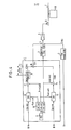
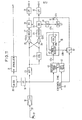
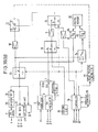
- The present invention is explained in further detail by referring to a concrete circuit example. There is shown a recording system in Fig. 4 which uses a magnetic disc as a magnetic medium and records luminance signals by FM modulation, and a reproducing system corresponding thereto in Fig. 5.
- In Fig. 4, the
reference numeral 1 denotes a rectangular 2-phase PM circuit, 2 an FM circuit for luminance signals, 3 a counter for forming reference signals, 4 a composite circuit, 5 a recording amplifier, 6 a magnetic head, 7 a magnetic disc, and 8 a driving motor. The rectangular 2-phase PM circuit 1 comprises acarrier oscillator 9, aphase shifter 10, twobalanced modulators composite circuits inversion circuit 16. From the output (assuming fH to be horizontal scanning frequency, e.g. 756 KHz corresponding to 48 fH), of theoscillator 9, three different carriers of Acosωct, Asinωct, and -Asinωct are formed by thephase shifter 10. To one of the balanced difference modulators 11-are input, for instance, the color/signals R - Y and -Asinωct to output balanced modulation signals, to which is added Acosωct as a subcarrier in order to obtain R - Y carrier chromicance signal or PM color signal CR(t). To the otherbalanced modulator 12 are input B - Y color signals and Acosωct to output balanced modulation signals, to which is added A inωct as a subcarrier to obtain B - Y PM color signals CB(t). Of the PM color signals thus obtained, CR(t) may be input in theinversion circuit 16 to output an alter- nately inverted PM color signal ±CR(t) which is phase-inverted (by 180°) per 1 H by controlling with a rectangular wave of 1/2 fH. PM color signal C(t) is formed by composing and multiplexing ± CR(t) and CB(t), to which is further composed by frequency-multiplexing FM luminance signals Cy(t) consisting of luminance signals Y which have been FM modulated and the reference signal fP of 6fH obtained by dividing the carrier to, for instance, 8 at thecounter 3, and finally recording the same in the magnetic disc 7. The recording track generally is shaped concentrically in the still video recording, and spirally in the movie recording. The recording modes employed are; rotating, for instance, the magnetic disc at 1,800 rpm in NTSC to record 1 track/l frame; and rotating at 3,600 rpm to record 1 track/1 field or 2 tracks/l frame. - We shall now explain the principle of PM modulation by using a balanced modulator. Supposing the carrier is Acoswot modulation signal f (t) , and disregarding the constant, PM signal C(t) which has been phase modulated becomes the following equation;
- (b) At least one of the two PM color signals, the first subcarrier and the second subcarrier, is inverted or phase-shifted per every 1 H, and the two PM color signals are processed so as to phase-shift by 180° relatively per every 1 H in the process of recording.
- (c) When such a process is performed, multiplexed PM color signals may be delayed by 1 H at the time of reproduction, separated to two PM color signals by addition and subtraction of the signals before and after 1 H delay; and then each of the PM color signals is demodulated by the phase reference signal phase-shifting similar to the phase shift at the time of recording, thereby enabling a complete demodulation without DC residual component. Separation by addition/subtraction of PM color signals utilizes the fact that color signals of color picture image signals have a strong vertical correlation among horizontal scanning lines.
- (d) In rectangular 2-phase PM modulation of color signals, a circuit may be constructed simply by using a balanced modulator. Demodulation can also be conveniently conducted by using a balanced modulator. Any PM demodulation method can naturally be employed just as any PM modulation method can be employed for recording.
- The above going explanation is based on the premise that color picture image signals are recorded on magnetic tapes and discs, but the same is true of transmission systems where signals are transmitted by wire without magnetic recording and then demodulated, or of any other types of picture data storage systems. Since a wider frequency band can be taken for the transmission systems, etc. for example two color differenc signals of (R - Y) A (B - Y) A, and (R - Y) B (B - Y) B' and two luminance signals of YA and YB may be multiplexed by rectangular 2-phase PM modulation against two color picture image signals A and B as shown in fig. 3 Naturally, magnetic recording can also do this.
- Figs. l(a) and l(b) are diagrams to explain difficulties encountered in the prior art; Figs. 2 and 3 to explain the present invention; Fig. 4 a block diagram showing one embodiment of the recording system; Fig. 5 a block diagram showing one embodiment of a regenerating system corresponding to that shown in Fig. 4; Fig. 6 shows changes in Bessel functions; Fig. 7 shows examples of recording/regenerating methods without cross talk; Fig. 8 another example of the -regeneration system; Fig. 9 explains the inversion control for phase reference signals; Fig. 10 shows a concrete circuit diagram thereof; Fig. 11 is a block diagram showing still another embodiment of the regeneration system; Fig. 12 explains an inclined azimath system; Fig. 13 is another embodiment to explain the recording system; Fig. 14 shows still another embodiment; Fig. 15 is a block diagram of a regeneration system corresponding to that of Fig. 14; Figs. 16(a) and 16(b) simplified block diagrams showing 2 devices provided with

- If K-f (t) <<1at all times t, the equation (1) becomes the following;


- Provided, however, mp = K.a, and represents the maximum modulation index. On the other hand, when (3) is substituted in (1) and expanded to the primary equation with the first kind of Bessel function,

- From (4) and (5), the range which holds

- mp ≤ 1.3 or mp < 1.5 for practical purposes.... (7), then (6) holds with a fairly good approximation.
- From the above consideration, it is clear that if the modulation index is beneath a certain value, then it may be PM modulated by a balanced modulator. It also becomes clear that multiplexing of PM signals by rectangular 2-phase modulation is also possible.
- In further considering the maximum modulation index, mp upper limit is more or less determined visually. According to Japanese Patent Publication No. 56-51406 and Lay open print 53-41126, the luminance signal is-PM modulated at mp ≤ 1.0 (or mp < 1.3 for practical purposes) for allowing cross talks from the adjacent tracks. However, when one considers that the color signals have a narrower band width than the luminance signals, mp = 1.5 will suffice in practical terms. More in particular, when PM modulating by using a balanced modulator, mp may further be increased than the conventional PM modulation because of the absence of secondary side band waves. A large mp is also allowed for still picture recording, since recording may be carried out to eliminate cross talks. When mp is large, S/N improves, but distortion increases. This distortion is amendable.
- When Asinact and Acoswot are PM modulated by a balanced modulator which are in a perpendicular relation to each difference other by using two difference color signals (R - Y) and (B - Y) as modulation signals, following two equations will hold.


- When demodulating ER-Y and EB-Y respectively and separately in (8) and (9), they may be synchronously detected as
- CR(t) x sinwot, and C (t) x coswot.
- However, if simply multiplexed as in

- In order to eliminate the DC component mentioned above, CR(t) and CB(t) are so set for frequency-interleaving of each other. By using the vertical correlation of picture image signals, either one of CR(t) or CB(t) is phase inverted in 1 H so as to enable their separation by a comb filter at the time of reproduction, or further still a phase is advanced by 90 degrees for 1 H for one and delayed by 90 degrees for the other, so that CR(t) and CB(t) will be phase-shifted by 180 degrees relative to each other per 1 H for multiplexing. There are two methods of phase shifting; one is to phase shift the modulator output by ±180°aad ±90°, and the other is to phase shift the carrier by ±180° and ±90°.
- In Fig. 4,

- For demodulation,. C(t) is delayed by 1 H because of the strong vertical correlation existing between adjacent -horizontal-scanning lines of the picture image signal , so that C(t) may be separated to CR(t) and CB(t) by addition and subtraction of the signals before and after the delay. After separation, they may be respectively synchronous- detected. As it becomes ±CR(t) in subtraction, the phase reference signal used in the synchronous detection is also phase inverted per 1 H to become ±sinwct. Such phase shift of phase reference signals per 1 H becomes necessary for, say,when CR(t) is advanced by 90 degrees as well as for deiaying CB (t) by 90 degrees per 1 H. In other words, the phase shift angle for the phase reference signal is determined by those of CR(t) and CB(t) during recording. Said separation becomes incomplete if the respective subcarrier phases do not align in each horizontal scanning. Therefore, the frequency Wc/2π of subcarriers is related to horizontal scanning frequency fH. For rotating disc, for instance, Wc/2π = n·fH for 1 track/l frame, and

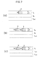
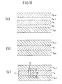
- In magnetic recording of still picture images, there is generally no correlation among still pictures recorded in adjacent tracks with different image pickup units whether for frame recording or field recording. Thus, there should be no cross talks with other picture images on the adjacent track. Generally speaking, there is formed a guard band gn between the track tn and tn + 1 as shown in Fig. 7(a). However, still generally speaking, the scanning widthℓ HP for reproducing
magnetic head 17 is the same as the width ℓt of the recording track. In the case of the guard band shown in Fig. 7(a) with admittedly few cross talks, because of ℓHP =ℓt if the reproducinghead 17 deviates from the recording track tn, to that extent reproduced output becomes lowered, thereby deteriorating S/N. This requires a tracking servo control with excellent precision; but if the reproducinghead 17 becomes randomly deviated from the recording tack t during one rotation because of eccentric loading of the magnetic disc 7, this becomes a random deviation in the reproduction output, and the resulting random S/N lowering cannot be compensated. In order to remove such inconveniences, the relation between the scanning width ℓHR of therecording head 6 and that ℓHP of the reproducinghead 17 should be set as
- Take a magnetic disc of about 40 mmø plastic film base, the track deviation at its worst becomes ± 20 µm considering the thermal expansion, wet expansion and decentering, If the recording track width ℓt was set at 80 µm (ℓHR= 80 µm) , and the scanning width ℓHR of the reproducing
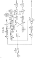
head 17 be 40 µm, a constant reproduction output with a simple tracking can be output. If the reproduction head width is 40 pm, sufficient S/N is obtainable with the present day technology. So long-as the above equation (12) is satisfied, it does not matter whether a guard band is formed as in Fig. 7(b) or not as in Fig. 7(c). - Fig. 5 shows an embodiment of the reproduction system corresponding to the recording system of Fig. 4 wherein the
reference numeral 17 denotes a magnetic head for reproduction, 18 a reproduction amplifier, 19 to 21 a high pass filter for separating FM luminance signals, an amplitude limiter, an FM demodulator respectively, and 22 a demodulator circuit for multiplexed FM color signals. Thedemodulator circuit 22 of this embodiment comprises a band pass filter (BPF) for PMcolor signal extraction 23, a delay line for 1 horizontal scanning time (1HDL) 24, asubtractor 25, anadder 26,amplitude limiters balanced modulators reference signal generator 33. The phasereference signal generator 33 of this particular embodiment comprises a 48fH oscillator 34, aphase shifter 35 and aninversion circuit 36. Theoscillator 34 of this embodiment comprises a band pass filter (BPF) 34a for extracting 6fH reference signals, anamplitude limiter 34b, avoltage control oscillator 34c, acounter 34d for 1/8 frequency division, and aphase comparator 34e. - In Fig. 5, FM luminance signal CY(t) among reproduced signals 37 is FM demodulated as in the prior art. Multiplexed PM color signals (±CR(t) + CB (t) ) are separated to ±CR(t) and CB(t) by the
delay line 24, thesubtractor 25 and theadder 26 after having been extracted by theband pass filter 23, and then input to balanced modulators (BM) 29 and 30 respectively after passing through theamplitude limiters balanced modulators voltage control oscillator 34c is frequency-divided by 8 at thecounter 34d, and is phase-compared with the 6f reference signal f'P obtained by passing the output through the band pass-filter 34a and theamplitude limiter 34b at thephase comparator 34e in order to control the phase of the oscillation output. From this oscillation output are formed sin t and coswct at thephase shifter 35, and coswct is given as is to thebalanced modulator 30 for B - Y demodulation. Sinwct is passed through theinversion circuit 36 which is controlled by 1/2fHrectangular signal 38 inverting once per every 1 H to make it ±sinwct, and is given to abalanced modulator 29 for R - Y demodulation. When the output from each of thebalanced modulators - We shall now discuss the phase reference signals. The phase reference signals necessary for synchronous detection must absorb time base deviations caused by the relative movement of the magnetic disc and the magnetic head at either the time of recording or of reproducing. In the embodiment shown in Figs. 4 and 5, the 6fH reference signal fp is recorded by frequency multiplexing along with FM luminance signals and PM color signals. At the time of demodulation, the 6fB reproducing signal f'P is used to align the phase of the phase reference signal with the time base deviation. Said reference signal is set on the side lower than the PM color signal band as for 6fH, although it may be set between PM color signal zone and FM luminance signal zone. More concretely, if the subcarrier is set at about 1.3 MHz and the reference signal at the frequency twice thereof, then the design and circuit construction for the phase reference signal generator becomes simple when considering the jitters, phase lags or S/N. Other methods of obtaining phase reference signals are a method to provide an auxiliary track on the magnetic disc and recording either one of the subcarriers thereon; a method for using the composite signals of the first and the second subcarriers during the horizontal blanking period; or a method of phase control by detecting the rotational deviation of the disc driving motor at FG (frequency generator). With a method of using auxiliary track or FG, the subcarrier phase is controlled also during recording.
- When one of PM color signals CR(t) is inverted alternately with ±CR (t) per every 1H as the recording system shown in Fig. 4, unless the phase reference signals correctly respond and invert in-reproduction demodulation as


- As shown in Fig. 8, one
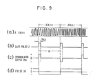
more PM demodulator 39 is added to the circuit shown in Fig. 5; and the signal ±C'R(t) alone is extracted during the horizontal blanking by thegate circuit 40 from among the alternately inverting PM color signals ±CR(t), signal ±C'R(t) being PM demodulated by a signal of a prescribed phase, for instance, a phase reference signal coswct for CB (t) demodulation. Thus, thecontrol signal 38 for theinversion circuit 36 is to be formed from said PM demodulation output 39a. Alternately inverting PM color signal ±CR(t) is generally expressed as

gate circuit 40 with thegate pulse 41 which becomes ON by every 1 H during the horizontal blanking period TBLK as shown in Fig. 9(b), and PM demodulated with coswct to obtain a demodulation output 39a which becomes positive or negative per every 1 H as shown in Fig. 9(c). When the pulse 39a is input into acomparator 42 having hysterisis characteristics, 1/2fH pulse signal whose level deviates per every 1 H as shown in Fig. 9(d) is obtained. Vref represents a threshold value. The level of thepulse signal 38 always corresponds to ±CR(t) by following the polarity of the demodulated output 39a during horizontal blanking which always corresponds to the alternately inverting PM color signal ±CR(t). Therefore, it is possible to obtain discriminating pulse signals without recording special pulses. - Furthermore, even when burst errors occur, the
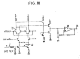
pulse signal 38 automatically returns to the level transition correspond- . ing to ±CR(t). In the example shown in Fig. 4, theinversion circuit 36 comprises an inverter 36a and a switch 36b, said switch 36b being switched corresponding to the level of pulse signals 38. In Fig. 8, the parts identical to those shown in Fig. 4 are given the same reference numerals in order to avoid redundancy in explanation. - Fig. 10 shows a
PM demodulator 39, agate circuit 40 and a concrete circuit for thecomparator 42 which has hysteresis characteristics. - Fig. 11 shows a reproducing system corresponding to the recording system of Fig. 4 when phase reference signals are formed by an alternate method. Provided, however, the recording system does not require the
counter 3 of Fig. 4. In Fig. ll, the parts identical to those shown in Fig. 5 are given the identical reference numbers in order to avoid redundancy in explanation. - In Fig. ll, a
gate pulse circuit 43 inputs horizontalsynchronous signals 44 tooutput pulses 43a of the width of horizontal blanking period, and the referencesignal gate circuit 45 remains open while it receives thepulse 43a, and sends the burst reference signal (48fH) 45a to APC (automatic phase control)circuit 46. Since the horizontal blanking period for color signals lacks the signal component, the subcarrier phase becomes constant. Therefore, theoutput 45a of the referencesignal gate circuit 45 is a mere composite of the first and second subcarriers. InAPC circuit 46, the oscillation output 47a of VCO (voltage control oscillator) 47 is phase-compared with thereference signal 45a which has been input at aphasedetector circuit 48, and itsoutput 48a is used to controlVCO 47 to obtain the output 47a of the same phase and frequency as theburst reference signals 45a. This oscillation output 47a is a continuous signal corresponding to the time changes. The oscillation output 47a passes a 90°phase shifter 49 and becomes a phase reference signal cowct of a prescribed phase corresponding to thebalanced modulator 30 for B - Y modulation. On the other hand, a flip-flop (F/F) 50 relies on horizontalsynchronous signal 44 as a clock, and is reset by thesignal 48b output by thephase detector circuit 48 as it detects the phase ofburst reference signal 45a every time it is input. Accordingly, the output of the flip-flop is used to switch theswitch 51 by every 1 H, and the output 47a directly from VCO and theoutput 52a which has passed through a 180° phase shifter (inversion circuit) 52 are alternately given to thebalanced demodulator 29 for R - Y demodulation in order to obtain a phase reference signal of ±sinwot. This will achieve a stable demodulation which has absorbed time base changes. In the example of Fig. 11, one of the subcarriers becomes inverted at the time of recording to t sinwot, the phase for theburst reference signal 45a becomes different by 90 degrees per every 1 H similarly as the burst signals in PAL system. Therefore, it is not only stable against time-based changes, but it is possible to obtainsignals 48b for correctly inverting the phase reference signal to ±sinwct per 1 H from thephase detector circuit 48 of APC circuit. - In the above going explanation, the luminance signals are FM modulated for recording. Therefore, if reproduction is conducted with the magnetic head overriding the adjacent track, interference between FM luminance signals of adjacent tracks will interfere beats. If the subcarrier phases of PM color signals of adjacent tracks were not aligned, the colors for the reproduced picture image will also become deviated. As shown by hatched lines in Figs. 12(a) and 12(b), a so-called inclined azimath FM recording system is recommended so that a recording track tn will have a different azimath from the track tn-1, or the track tn+1 adjacent thereto. For the recording system, as shown in Fig. 13 for example, an
oscillator 53 comprisingVCO 53 a, acounter 53b and a recommended in place of theoscillator 9 in Fig. 4.phase comparator 53c is recommended in place of theoscillator 9 in Fig. 4. From already recorded track, reference signal f'p is reproduced by using an auxiliary head, or by recording this reference signal f'P in an auxiliary track, and then reproducing the same, this reference signal f'p is input in theoscillator 53, it is possible to align the subcarrier phases between adjacent tracks. In the latter case, the center frequency of the carrier may be used as the reference signal because there are no signal interferences. The position of recording vertical and horizontal synchronous signals should preferably be aligned between adjacent tracks, but it suffices so long as the recording positions of the horizontal synchronous signals if the vertical synchronous signals are not aligned. are aligned, As described above, if the positions of recording horizontal synchronous signals and of subcarriers were aligned between adjacent tracks and also if the inclined azimath system was adopted, it is possible to obtain reproduced picture images with less disturbances even if a tracking error occurs despite the efforts of preventing cross talks as shown in Figs. 7 (a), 7(b) and 7(c) in still picture video tape recording. In the case of movie recording, only the picture images with intense correlation with that of the adjacent track become overlapped, presenting little problem in high density recording. In this case, the scanning width ℓHP of the reproducinghead 17 may be made somewhat wider than the width of the recording track ℓT without any difficulties, and even with the tracking errors, the reproduction output is advantageously free from deviations. The parts in Fig. 13 which are identical to those of Fig. 4 are given the same numbers. - The above explanations were given in respect of various examples for recording the luminance signals by FM modulation. We shall now explain the instance where the luminance signals are PM modulated and recorded. Basically, it suffices if a PM modulator is used instead of an FM modulator in the recording system, and a PM demodulator in place of an FM demodulator in the reproducing system. PM modulator and PM demodulator can be realized quite simply by using a balanced modulator as in the modulation/demodulation of color signals.
- When PM modulating and recording both color signals and luminance signals, we might consider the still picture recording apart from the movie recording. In the former, recording/reproduction is carried out, in principle, to /by providing a guard band / restrain generation of cross talks by providing a guard had as shown in Figs. 7(a), 7(b) and 7(c). Therefore, it is not necessarily required to align the recording positions of horizontal synchronous signals between adjacent tracks, or to align the phases of subcarriers for multiplexed PM color signals and of main carriers of the PM luminance signals. Naturally, it is not a requisite either to adopt inclined- azimath system.
- On the other hand, high density recording becomes possible for the first time after the recording position for the horizontal synchronous color signais, the- phases of respective subcarriers of multiplexed PM color signals, and the phase of main carrier for the PM luminance signals between respective adjacent tracks are aligned. In this case, a plural number of picture images with extremely strong correlation alone become overlapped when the regeneration head overrides the adjacent tracks. This will not cause any beat interferences. Therefore, there is absolutely no need to adopt the inclined azimath method, but it is more preferable to use a wider reproduction head which would override a plural number of tracks because of its bigger reproduction output and lower precision requirements for tracking. In the case of still picture taping, if the recording position of horizontal synchronous signals and the phases of respective carriers were aligned between adjacent tracks for recording, a tracking error, if any, would only cause overlapping of a plural number of picture images which have not corrlation to each other without disturbance of the reproduced image.
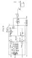
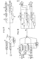
- Fig. 14 shows an example of a recording system for PM modulating and recording the luminance signals by using of balanced modulators. Fig. 15 shows an example of a reproducing system therefor. Except for the PM modulator/recorder for the luminance signals, the parts shown in these two figures are substantially the same and the like parts are given the like numbers in order to eliminate redundancy in explanation.
- The recording system shown in Fig. 14 is now explained. In the example, the center carrier for PM luminance, signals is set at ca. 7.8 MHz, and the center carrier for PM color signals at a
value 1/6th thereof (about 1.3 MHz) and the reference signals at 1/3 (about 2.6 MHz). 2.6 MHz indicates an empty frequency between the PM luminance signal band and the PM color signal band. - In Fig. 14, the
reference number 54 denotes a carrier generating circuit, which comprises a 2.6MHz oscillator 55, a 2.6 MHz band pass filter 56, anamplitude limiter 57, a change-over switch 58, a 1/2frequency divider 59, a 3multiplexing circuit 60, andphase shifters reference number 63 denotes a balanced modulator for PM modulating the luminance signals (Y), and 64 a composite circuit. - When recording on a new magnetic disc for the first time, the
switch 58 at a contact point a is turned ON, a fixed frequency output of theoscillator 55 is used for PM modulation, and PM luminance signal CY(t) and multiplexed PM color signals C(t) along with the 2.6 MHz reference signal f are multiple-recorded in one track. When recording in the next track, theswitch 58 at a contact point b is turned ON, the reference signal f'P (2.6 MHz) is extracted from the track by using an auxiliary head (not shown) and BPF 56 to form a required carrier. In all the tracks, phase for each carrier thus becomes aligned. The center frequency of each carrier may be recorded in the auxiliary track to be used as the reference signals. - Fig. 15 shows a regeneration system which is different from Fig. 4 or Fig. 8 in that PM luminance signals are demodulated at a
balanced modulator 65, and that 2.6 MBz reference signals f'p are frequency-divided to 1/2 'to form phase reference signal for PM color signal demodulation, and multiplexed by 3 to form phase reference signal for PM luminance signal demodulation. In the figure, thereference number 66 denotes a band pass filter, 67 an amplitude limiter, 68 a 1/2 frequency divider, 69 a multiplication circuit, and 70 a phase shifter. - Fig. 16 shows an example of a magnetic disc video recording device to which a system of magnetic recording/ reproducing still picture images by FM modulating luminance signals is applied in order to facilitate animation reproduction. Naturally, the explanation stands true for the case where still picture images are magnetic recorded/ reproduced by PM modulating the luminance signals. The circuit shown in Figs. 4, 5 and 8 is used also for the device shown in Fig. 16 and the identical parts are therefore given the identical numbers in order to eliminate redundant explanations. The example shown in Fig. 16(a) uses an auxiliary track formed on the magnetic disc 7, for instance, on the outermost periphery thereof for reproducing animations. The
reference number 71 denotes a composite main head for still picture recording and is integrally formed with awide head 6 and anarrow head 17 aligned in the direction of the track. The reference number 72 denotes a composite auxiliary head for reproducing animations which also includes awide head 73 and a narrow head 74 aligned integra in the direction of the track.Reference number 75 indicates an oscillator for erase signals, 76 a control member, 77 a control device for head positions, 78 a rotation counter for magnetic disc, 79 and 80 amplifiers for recording and regenerating, 81 an amplifier for extracting pilot signals for tracking, and S1 - S4 switches for mode changes. Themain head 71 for still picture recording is positioned on the desired track by moving the same in the radial direction of the magnetic disc, while the auxiliary head 72 for reproducing animations are fixedly positioned on the auxiliary track. The device shown in Fig. 16(a) has the three kinds of modes; SR for still picture recording, SP for still picture reproducing and AP for animation reproducing. Mode commands are input to thecontrol member 76. We shall now explain the operations of respective modes by referring to Table 1 assuming that the still picture images are recorded in the magnetic disc by 1 track/l field. Table 1 shows the contact selections of the switches corresponding to the modes. The contact point c for each of the switches indicates OFF.
- Switch S2 at contact point b alone is turned ON, and other switches Sl, S3 and S4 are turned OFF. From the regenerated output of the
wide head 6 of themain head 71 is extracted pilot signals for tracking to be fed in thecontrol member 76, and the signal to position themain head 71 on the desired track is given to the headposition control device 77, thereby to position themain head 71. [Erase] - Sl at contact point b and S2 at . contact point a become turned ON, and others are turned OFF. The output from the
oscillator 75. is amplified by theamplifier 5 for recording, and erasing current is passed to thewide head 6 of themain head 71. When always erasing before recording in each track, the erase mode is incorporated in the still picture recording mode SR. - Sl and S2 at the contact point "a' are turned ON, and the others become turned OFF. At the
composite circuit 4, FM luminance signals Cy(t), PM color signals C(t) and reference signals fp are multiplexed and amplified, and then the picture image signals corresponding to 1 field are recorded in the desired track by thewide head 6 of themain head 71. - S3 at the contact point a is turned ON, and others become turned OFF. The reproduction output from the
narrow head 17 of themain head 71 is amplified at theamplifier 18, and demodulated similarly as in Fig. 5 or Fig. 8. This will repeatedly obtain the picture image signals for 1 field portion to reproduce the still picture. - When the changing object is continuously pictured by still recording, it is generally difficult to.-smoothly reproduce moving pictures. Basically, it suffices if reproduction is conducted a plural number of times for the same track, then moves on to the next track to repeat the same procedure subsequently. However, when the head moves from one track to another track, the reproduced picture image becomes blurred.
- [1] First, S3 and S4 alone at the contact point a are turned ON, and others are turned OFF; the reproduction output from the
narrow head 17 of themain head 71 is demodulated, and at the same time this output is amplified, and recorded in an auxiliary track by thewide head 73 of the auxiliary head 72. When thecounter 78 detects one rotation of the magnetic disc, , - [2] S3 at the contact point b alone becomes turned ON immediately to be reproduced from the auxiliary track which had recorded the record immediately preceding thereto by using the narrow head 74 of the auxiliary head 72. This reproduction is continued for the prescribed number of times of the magnetic discs, while the
main head 71 is slowly sent to the next track. When thecounter 78 detects the prescribed number of rotation, the operation mentioned in [1] is repeated to the next track. By repeating the above, the reproduced picture image does not become blurry during the time the head moves, and animation is reproduced excellently. The above explanation for Fig. 16(a) was made in respect of the field record of 1 track/l field. The same is true for the frame record of 1 track/l frame. When frame recording 2 tracks/1 frame, there should be provided two compositemain heads 71 for still picture recording for the first field and the second field. There should also be provided two composite auxiliary heads 72 for the auxiliary track/ animation reproduction for the first and the second fields, and each head may be electrically switched for each of the fields. - Fig. 16(b) shows an example where a
digital memory 82 for 1 field or 1 frame is shown-instead of the auxiliary track. This is the same as the example shown in Fig. 16(a) except for A/D converter 83 and D/A converter 84. - Figs. 17 and 18 show the instances where the present invention is applied to a transmission system. In these figures, the like parts shown in Figs. 4, 5 and 8 are allotted the like numbers to simplify the explanation.
- The embodiment shown in Fig. 17 shows transmission of one color picture image signal. In the figure, the
reference number 85 denotes a PM or FM angle modulator for luminance signals, 86 a transmission line, and 87 a PM or FM demodulator for carrier luminance signals. The carrier luminance signal allotted with bands and multiplexed PM color signals as shown in Fig. 2 are transmitted over thetransmission line 86. - Fig. 18 shows an example of transmitting two color picture image signals A and B. As in Fig. 3, the band.zones are allotted for occupation by respective signals and multiplexed by rectangular 2-phase PM modulation respectively. In the figure, the reference numbers la and lb denote PM modulator circuits which are similar to the
PM modulator circuit 1 except that the former do not have a carrier oscillator. They obtain the carrier at themultiplexers reference numbers PM demodulator circuit 22 except for the pass band for the band pass filter, and 33a and 33b are the circuits with the same construction as the phase referencesignal generating circuit 33 except for frequency. - The present invention is now explained when applied generally to storing devices by way of Figs. 19 and 20. The example shown in Fig. 19 corresponds to that of Fig. 17 and is the same except that the storing
device 90 is used instead of thetransmission line 86. The example of Fig. 20 corresponds to that of Fig. 18 except for the use of a storing device in place of thetransmission line 86. The storing device requires an amplifier on both the input side and the output side as the need arises similarly as in the transmission system. - As a
storing device 90, any of the like devices mentioned below may be used; - ⓐ A memory which converts the modulated
signals 4a output from thecomposite circuit 4 into optical signals by an electric/optical converter (including LED and laser), and exposing 'the'light sensitive material made of silver halogenide by optical signals in beam to optically record the data, and a memory to record the optical signals in beam by emitting the same on an optical magnetic recording medium< - (b) Various electrostatic capacity memory and semiconductor memory which.store the
output 4a of thecomposite circuit 4 as an electrical amount without converting the same to magnetic force or light, - (c) Various digital magnetic memories which convert the
output 4a of thecomposite circuit 4 into digital signals and store the same. - The optical magnetic memory, the semiconductor memory, and the magnetic memory basically convert the
output 4a of thecomposite circuit 4 to digital signals by PCM or PNM systems, but other storage devices often can store the output as analog or digital signals. In such a case, theoutput 4a of thecomposite circuit 4 may be stored as analog record without change, or it may be sampled once and stored as PAM, or even still may be converted to PWM and stored. Provided, however, theoutput 90a of thevarious storing devices 90 must be converted into base band signals or the same form as theoutput 4a of thecomposite circuit 4 by the detection circuit or D/A converter if they are sampled and recorded in PAM and PWM, or in PNM and PCM, except where theoutput 4a of thecomposite circuit 4 is analog recorded as a whole.
Claims (30)
- (1) A rectangular 2-phase phase modulation method characterized in that a first and a second carriersperpendi- cular to each other are PM modulated by one of the two color signals or of the two luminance signals, at least one of the four signals consisting of two PM modulated signals, the first and the second carriers is inverted or phase-shifted in such a way that these two PM modulated signals would become phase shifted by 180 degrees relative to each other per one horizontal scanning period by the time these two PM signals reach their input means, and these PM modulated signals phase-shifted by 180 degrees relative to each other are multiplexed for input in said input means.
- (2) The rectangular 2-phase phase modulation method as claimed in Claim 1 characterized in that said PM modulation uses a balanced modulation wherein PM modulated waves are obtained by composing the balanced modulation output of signals pouring the carriers to be balance- modulated by each signal with other carriers of a phase delayed by 90 degrees.
- (-3) The rectangular 2-phase modulation method as claimed in one of the claims 1 or 2 characterized in that said input means is a storing device.
- ( 4 ) The rectangular 2-phase phase modulation method as claimed in claim 3 characterized in that said storing device includes a magnetic medium and a magnetic head moving relative thereto, and is a magnetic recording device for recording input signals.
- ( 5 ) The rectangular 2-phase phase modulation method as claimed in claim 4 characterized in that the two signals to be PM modulated are the two color signals of the color picture image signals, and said magnetic recording device records by frequency division multiplexing the multiplexed PM color signals and the carrier luminance-signals obtained by angle modulating the main carrier with the luminance signals of said color picture image signals.
- ( 6 ) The rectangular 2-phase phase modulating method as claimed in claim 5 characterized in that the modulating method for said luminance signals is a PM modulating method, the main carrier for PM luminance signals and the first and the second carriers for PM color signals are synchronized along with the relative movement of the magnetic head and the magnetic medium, and said magnetic recording device records PM luminance signals and multiplexed PM color signals in such a way that at least the recording position of horizontal synchronous signals of the color picture image signals will become aligned in adjacent tracks and the phase of said main carrier, the first and the second carriers wifl become aligned in adjacent tracks.
- ( 7 ) The rectangular 2-phase phase modulating method as claimed in claim 5 characterized in that the modulation method for said luminance signals is a frequency modulating method, the first and the second carriers for PM color signals are synchronized with the relative movement of the magnetic head and the magnetic medium, said magnetic recording device records FM luminance signals and multiplexed PM color signals in such a way that at least the recording position of the horizontal synchronous signals of the color picture image signals will become aligned in adjacent tracks, and the phases of the first and the second carriers will become aligned but with different. azimath in adjacent tracks.
- ( 8 ) The rectangular 2-phase phase modulation method as claimed in one the claims 5 to 7 characterized in that said color picture image signals are the signals of still picture images.
- ( 9 ) The rectangular 2-phase phase modulation method as claimed in claim 8 characterized in that the width of the recording track formed by said magnetic recording device is wider than the scanning width of the magnetic head for reproducing.
- ( 10) The rectangular 2-phase phase modulation method as claimed in one of the claims 6 or 7 characterized in that said color picture image signals are the signals of movie picture images.
- ( 11) The rectangular 2-phase phase modulation method as claimed in claim 10 characterized in that said width of the recording track formed by said magnetic recording device is narrower than the scanning width of the magnetic head for reproducing.
- ( 12) The reotangular 2-phase phase modulation method as claimed in one of the claims 9 or 11 characterized in that said magnetic recording device is formed by closely adhering the recording tracks.
- ( 13) The rectangular 2-phase phase modulation method as claimed in one of the claims 1 or 2 characterized in that said input means is a device to transmit multiplexed PM signals.
- ( 14) The rectangular 2-phase phase modulation method as claimed in claim 13 characterized in that said two signals to be PM modulated are the two color signals of the color picture image signals, and said transmission device transmits by frequency multiplexing the multiplexed PM color signals and the carrier luminance signals obtained by angle modulating the main carrier with the luminance signals of said color picture image signals.
- ( 15) The rectangular 2-phase modulation method as claimed in Claim 13 characterized in that said two signals to be PM modulated are respectively luminance signals of the two color picture image signals, and said transmission device transmits multiplexed PM luminance signals and four carrier color signals obtained by modulating four color signals of said two color picture image signals with an arbtirary angle modulation method.
- ( 16) In a demodulation method of two color signals or two luminance signals from the signals multiplexed by PM modulation from an input means wherein the first and the second carriers perpendicular to each other are phase modulated by one of the two color signals or of the two luminance siqnals, at least one of the four signals consisting of the two PM signals, the first and the second carriers is inverted or phase-shifted per 1 horizontal scanning period in such a way that these two PM signals will become phase shifted by 180 degrees relative to each other per 1 horizontal scanning period by the time these two PM signals reach their imput means, and said PM signals which besome phase shifted by 180 degrees relative to each other are multiplexed and input, a demodulation method for signals multiplexed by a rectangular 2-phase phase modulation characterized in that said multiplexed PM signals are delayed by 1 horizontal scanning time, separated into two PM signals by the addition and subtraction before and after the delay, and thus separated PM signals respectively are PM demodulated by the phase reference signals which phase shift similarly as in modulation.
- ( 17) The demodulation method as claimed in Claim 16 characterized in that said input means is a storing device.
- (,18) The demodulation method as claimed in Claim 17 characterized in that said storing device includes a magnetic medium and a magnetic head which moves relative thereto, and is a magnetic recording device recording input signals.
- ( 19) The demodulation method as claimed in Claim 18 characterized in that the two signals to be PM modulated are the two color signals of color picture image signals, and in said magnetic medium are recorded by frequency dvision multiplexing multiplexed PM color signals and carrier luminance signals obtained by angle modulating the main carrier with the luminance signal of said color picture image signals and also demodulates multiplexed PM color signals obtained by extracting from the output of the magnetic head.
- ( 20) The demodulation method as claimed in Claim 19 characterized in that the lumiance signals stored in said magnetic medium are PM modulated, and in said magnetic medium are recorded PM luminance signals and multiplexed PM color signals in the state that the recording position of at least the horizontal synchronous signals of the color picture image signals are aligned in adjacent tracks and the phase of the main carrier for PM luminance signals and the phase of teh first and the second carriers of the multiplexed PM color signals are aligned to each other in adjacent tracks.
- ( 21) The demodulation method as claimed in Claim 19 characterized in that the luminance signals stored in said magnetic medium are PM modulated, and in said magnetic medium are recorded PM luminance signals and multiplexed PM color signals in the state that the recording position of at least the horizontal synchronous signals of the color picture image signals are aligned in adjacent tracks and the phase of the main carrier for PM luminance signals and the phase of the first and the second carriers of the multiplexed PM color signals are aligned in adjacent tracks but with different azimath.
- ( 22) The demodulation method as claimed in one of the Claims 19 to 21 characterized in that the color picture image signals recorded in said magnetic medium are the signals of still picture images.
- ( 23) The demodulation method as claimed in Claim 22 characterized in that the scanning width of said reproducing head is narrower than the width of the recording track formed on the magnetic medium.
- ( 24) The demodulation method as claimed in one of the Claims 20 or 21 characterized in that the color picture image signals recorded in said magnetic medium are movie picture images.
- ( 25) The demodulation method as claimed in Claim 24 characterized in that the scanning width of said repro- ducing head is wider than the width of the recording track formed on the magnetic medium.
- ( 26) The demodulation method as claimed in one of the Claims 23 or 25 characterized in that recording tracks are formed closely to each other on said magnetic medium.
- 1( 27) The demodulation method as claimed in Claim 16 characterized in that said input means is a device to transmit multiplexed PM signals.
- (t28) The demodulation method as claimed in Claim 27 characterized in that said multiplexed PM signals are the two color signals of color picture image signals, and said transmission device transmits by frequency multiplexing the multiplexed PM color signals and the carrier luminance signals obtained by angle modulating the main carrier by the luminance signals of said color picture image signals.
- ( 29) The demodulation method as claimed in Claim 28 characterized in that said multiplexed PM signals are respectively the luminance of the two color picture image signals, and said transmission device transmits the multiplexed PM luminance signals and four carrier color signals obtained'by modulating four color signals of said two color picture image signals by an arbitrary angle mudulation.
- ( 30) The demodulation method as claimed in one of the Claims 16 to 29 characterized in that said multiplexed PM signal is the signal obtained by inverting one of the two PM signals in the process preceding multiplexed or one of the first and the second carriers per 1 horizontal scanning period, demodulation of PM signal separated by addition uses a phase reference signal of a prescribed phase, demodulation of PM signals separated by subtraction or alternatingly inverting PM signals uses a phase reference signal abtained by demodulating said alternatingly inverting PM signals with signal of a prescribed phase during the horizontal blanking period only and creating pulse signal of 1/2 frequency of horizontal scanning frequency which repeats level transition per 1 horizontal scanning period by thisdemodulated output, and controlling the phase inversion according to the level transition of said pulse signals.
Applications Claiming Priority (8)
| Application Number | Priority Date | Filing Date | Title |
|---|---|---|---|
| JP57137375A JPS5928787A (en) | 1982-08-09 | 1982-08-09 | Recording and reproducing system of color video signal |
| JP137375/82 | 1982-08-09 | ||
| JP162183/82 | 1982-09-20 | ||
| JP57162183A JPS5952983A (en) | 1982-09-20 | 1982-09-20 | Recording and reproducing system of color video signal |
| JP104104/83 | 1983-06-13 | ||
| JP58104106A JPS59229710A (en) | 1983-06-13 | 1983-06-13 | Pm modulation and demodulation system of rectangular double phase |
| JP104106/83 | 1983-06-13 | ||
| JP58104104A JPS59229984A (en) | 1983-06-13 | 1983-06-13 | Magnetic recording and reproducing system for still picture |
Publications (3)
| Publication Number | Publication Date |
|---|---|
| EP0102552A2 true EP0102552A2 (en) | 1984-03-14 |
| EP0102552A3 EP0102552A3 (en) | 1987-02-25 |
| EP0102552B1 EP0102552B1 (en) | 1991-11-06 |
Family
ID=27469184
Family Applications (1)
| Application Number | Title | Priority Date | Filing Date |
|---|---|---|---|
| EP83107866A Expired EP0102552B1 (en) | 1982-08-09 | 1983-08-09 | Rectangular 2-phase modulation and demodulation methods for a colour picture signal |
Country Status (3)
| Country | Link |
|---|---|
| US (1) | US4626928A (en) |
| EP (1) | EP0102552B1 (en) |
| DE (1) | DE3382449D1 (en) |
Families Citing this family (4)
| Publication number | Priority date | Publication date | Assignee | Title |
|---|---|---|---|---|
| KR920002273B1 (en) * | 1989-07-08 | 1992-03-20 | 삼성전자 주식회사 | Quadrature modulation and demodulation method and circuit using remoting pll |
| WO1991007720A1 (en) * | 1989-11-16 | 1991-05-30 | International Business Machines Corporation | Method and apparatus for magnetic recording of data |
| US5426655A (en) * | 1991-07-16 | 1995-06-20 | International Business Machines Corporation | Method and apparatus for magnetic recording of data |
| US7227585B1 (en) | 2003-12-30 | 2007-06-05 | Conexant Systems, Inc. | Luminance and chrominance separation system |
Citations (6)
| Publication number | Priority date | Publication date | Assignee | Title |
|---|---|---|---|---|
| GB675887A (en) * | 1950-01-19 | 1952-07-16 | Pye Ltd | Improvements in or relating to television |
| US3849594A (en) * | 1973-05-25 | 1974-11-19 | Westinghouse Electric Corp | Multi-picture tv system with audio and doding channels |
| US3968514A (en) * | 1973-12-28 | 1976-07-06 | Sony Corporation | Magnetic recording and/or reproducing apparatus |
| US3992719A (en) * | 1974-04-09 | 1976-11-16 | Sony Corporation | Video signal recording/reproducing apparatus wherein the phase of the recorded signal is synchronized with the scanning head |
| US4217603A (en) * | 1978-11-06 | 1980-08-12 | Basf Aktiengesellschaft | Method and apparatus for processing color television signals |
| EP0024744A2 (en) * | 1979-09-03 | 1981-03-11 | Matsushita Electric Industrial Co., Ltd. | Portable color video signal recording apparatus |
Family Cites Families (3)
| Publication number | Priority date | Publication date | Assignee | Title |
|---|---|---|---|---|
| US3591707A (en) * | 1969-01-08 | 1971-07-06 | Gen Electric | Color television demodulator |
| NL6908782A (en) * | 1969-06-10 | 1970-12-14 | ||
| FR2479629B1 (en) * | 1980-04-01 | 1985-11-08 | Thomson Csf | METHOD FOR DEMODULATING AN AMPLITUDE MODULATED SIGNAL, DEMODULATOR IMPLEMENTING THIS METHOD AND TELEVISION SYSTEM COMPRISING SUCH A DEVICE |
-
1983
- 1983-08-02 US US06/519,730 patent/US4626928A/en not_active Expired - Lifetime
- 1983-08-09 DE DE8383107866T patent/DE3382449D1/en not_active Expired - Lifetime
- 1983-08-09 EP EP83107866A patent/EP0102552B1/en not_active Expired
Patent Citations (6)
| Publication number | Priority date | Publication date | Assignee | Title |
|---|---|---|---|---|
| GB675887A (en) * | 1950-01-19 | 1952-07-16 | Pye Ltd | Improvements in or relating to television |
| US3849594A (en) * | 1973-05-25 | 1974-11-19 | Westinghouse Electric Corp | Multi-picture tv system with audio and doding channels |
| US3968514A (en) * | 1973-12-28 | 1976-07-06 | Sony Corporation | Magnetic recording and/or reproducing apparatus |
| US3992719A (en) * | 1974-04-09 | 1976-11-16 | Sony Corporation | Video signal recording/reproducing apparatus wherein the phase of the recorded signal is synchronized with the scanning head |
| US4217603A (en) * | 1978-11-06 | 1980-08-12 | Basf Aktiengesellschaft | Method and apparatus for processing color television signals |
| EP0024744A2 (en) * | 1979-09-03 | 1981-03-11 | Matsushita Electric Industrial Co., Ltd. | Portable color video signal recording apparatus |
Also Published As
| Publication number | Publication date |
|---|---|
| EP0102552A3 (en) | 1987-02-25 |
| EP0102552B1 (en) | 1991-11-06 |
| US4626928A (en) | 1986-12-02 |
| DE3382449D1 (en) | 1991-12-12 |
Similar Documents
| Publication | Publication Date | Title |
|---|---|---|
| EP0148378B1 (en) | Magnetic recording and playback apparatus | |
| CA1099813A (en) | Color video signal recording and/or reproducing system | |
| KR910005093B1 (en) | Apparatus for reproducing an information signal | |
| US4555735A (en) | Interconnection system between image pickup device and recording device | |
| CA1092704A (en) | Apparatus for recording and reproducing video signals on a magnetic tape movable at different speeds | |
| US4283737A (en) | Video signal reproducing apparatus with circuit avoiding skew distortion when operated at abnormal speed and/or direction | |
| US4134126A (en) | Color recorder having means for reducing luminance crosstalk in displayed image | |
| US4208673A (en) | Color recorder for reducing crosstalk | |
| US4188638A (en) | Color television signal having color-difference signals alternating between two carriers | |
| EP0102552B1 (en) | Rectangular 2-phase modulation and demodulation methods for a colour picture signal | |
| US4344082A (en) | Apparatus for recovering a frequency-converted chrominance component that is substantially free of cross-talk components | |
| EP0361804B1 (en) | Apparatus for recording and/or reproducing information signals | |
| US4654724A (en) | Recording method for video and audio signals in magnetic picture recording system | |
| US6137648A (en) | Magnetic tape and a method for recording and reproducing a plurality of different information signals on and from the magnetic tape | |
| US3992719A (en) | Video signal recording/reproducing apparatus wherein the phase of the recorded signal is synchronized with the scanning head | |
| JPH0534876B2 (en) | ||
| GB2040135A (en) | Pal system colour video signal recording | |
| US5793557A (en) | Signal reproducing apparatus | |
| JP2735322B2 (en) | Video tape recorder | |
| JPS605675Y2 (en) | PAL color video signal reproducing device | |
| JPS6015194B2 (en) | Recording and reproducing device for PAL color video signals | |
| JPS635957B2 (en) | ||
| JP2644054B2 (en) | Method converter | |
| JPS6136433B2 (en) | ||
| JPH0441869B2 (en) |
Legal Events
| Date | Code | Title | Description |
|---|---|---|---|
| PUAI | Public reference made under article 153(3) epc to a published international application that has entered the european phase |
Free format text: ORIGINAL CODE: 0009012 |
|
| AK | Designated contracting states |
Designated state(s): DE FR GB |
|
| PUAL | Search report despatched |
Free format text: ORIGINAL CODE: 0009013 |
|
| AK | Designated contracting states |
Kind code of ref document: A3 Designated state(s): DE FR GB |
|
| RAP1 | Party data changed (applicant data changed or rights of an application transferred) |
Owner name: FUJI PHOTO FILM CO., LTD. |
|
| 17P | Request for examination filed |
Effective date: 19870821 |
|
| 17Q | First examination report despatched |
Effective date: 19890717 |
|
| GRAA | (expected) grant |
Free format text: ORIGINAL CODE: 0009210 |
|
| AK | Designated contracting states |
Kind code of ref document: B1 Designated state(s): DE FR GB |
|
| REF | Corresponds to: |
Ref document number: 3382449 Country of ref document: DE Date of ref document: 19911212 |
|
| ET | Fr: translation filed | ||
| PLBE | No opposition filed within time limit |
Free format text: ORIGINAL CODE: 0009261 |
|
| STAA | Information on the status of an ep patent application or granted ep patent |
Free format text: STATUS: NO OPPOSITION FILED WITHIN TIME LIMIT |
|
| 26N | No opposition filed | ||
| REG | Reference to a national code |
Ref country code: GB Ref legal event code: IF02 |
|
| PGFP | Annual fee paid to national office [announced via postgrant information from national office to epo] |
Ref country code: GB Payment date: 20020716 Year of fee payment: 20 |
|
| PGFP | Annual fee paid to national office [announced via postgrant information from national office to epo] |
Ref country code: FR Payment date: 20020819 Year of fee payment: 20 |
|
| PGFP | Annual fee paid to national office [announced via postgrant information from national office to epo] |
Ref country code: DE Payment date: 20021029 Year of fee payment: 20 |
|
| PG25 | Lapsed in a contracting state [announced via postgrant information from national office to epo] |
Ref country code: GB Free format text: LAPSE BECAUSE OF EXPIRATION OF PROTECTION Effective date: 20030808 |
|
| REG | Reference to a national code |
Ref country code: GB Ref legal event code: PE20 |